SG 6128 A Series User manual

Installation Instructions
Model 6128 A-Series
Electronic Safe Lock
• FürAnweisungenaufDeutschbesuchenSiebittediefolgendeWebsite:
• Paraobtenerinstruccionesenespañol,visitelasiguientepáginaweb:
• Pourobtenirlesinstructionsenfrançais,veuillezconsulterlesiteci-dessous:
• Peristruzioniinlinguaitaliana,visitareilsitowebseguente:
• ForinstructionsontheChineseversion,pleasevisitthefollowingURL:
Mounting Considerations
• Sargent&Greenleaf6100seriesMotorizedElectronicCombinationLockshave
beendesignedtousethesamemountingscrewlocationsandoccupythesame
spaceasmostotherS&Glocks,bothmechanicalandelectronic.
• Modicationstothelock(includinglockboltattachments)arenotrecommended,
andwillvoidtheyourwarranty.
• Aminimumdistanceof.150”(3,8mm)isrequiredbetweentheendofthelockcasecontainingthebolt
andtheclosestapproachofthesafe’sblockingbarorcamplatewhichisnormallyblockedbytheextended
lockbolt.Donotallowthesafe’sblockingbarorcamplatetodepresstheelectroniclock’sboltfartherthanit
retractsduringnormalmotoroperation.iscanleadtoinconsistentlockoperation.
• e6100seriesrequirestwo9-voltalkalinebatteries(mayormaynotbeincludedwithyourlockdepending
onthespecickitordered).WerecommendDuracell®batteries.Donotuseoldorpartiallydrainedbatteries.
Attaching Screws: Useonlythescrewsprovidedwiththelock.Lockbodymountingscrewswillbe
either¼-20orM6,dependingontheapplication.eymustengagethemountingplatebyatleastfour
fullthreads.Donotuselockwashersorthreadsealingcompoundsunlessspecicallydirectedtodoso
inthefullinstallationinstructions
Recommended Attaching Screw Torque: 30to40inch-pounds(3.4to4.5Nm)forthelockbody.No
morethan15inch-pounds(1.695Nm)forthekeypadattachingscrews.
Minimum Lock Cable (Spindle) Hole Diameter: 0.312”(7,9mm)MaximumLockCable(Spindle)
HoleDiameter:0.406”(10,3mm)LockisDesignedtoMove:0.0lbs.(0Newtons)
Lock Bolt Maximum Free Movement: 0.352”(8,95mm)Atleast0.109”(2,77mm)ofthelockbolt
remainsoutsidetheedgeofthelockcasewhenboltisfullyretracted.
Maximum Bolt End Pressure:Lockisdesignedtowithstandatleast225lbs.(1000Newtons)
MaximumBoltSidePressure:Safeandcontainerboltworkorlockingcamdesignsmustneverapply
morethan225lbs.(1000Newtons)ofsidepressureonthelockbolt.
Interface with Boltwork:islockisnotintendedfordirectboltworkattachment.Beforeinstalling
thelock,operatethesafeopeningmechanismandverifythattheinstalledpositionwilleectively
securetheboltworkswhenthelockislocked.Aerinstallation,checkthatthereiaclearancebetween
thecombinationlockboltandtheboltworks;aspressureontheboltcouldaectthelock’sabilityto
functionproperly.
Mounting Environment:elockbodyisdesignedtobemountedinsideasecurecontainer.e
containermustbeconstructedtooerprotectionagainstphysicalattackdirectedatthelock.e
amountofprotectionisdependentonthedesiredlevelofsecurityforthesystemasawhole.Lock
protectionmayincludebarriermaterials,relockdevices,thermalbarriers,thermalthese.Relockdevice
attachingscrewsmustNOTbelongerthanthedepthofthetappedattachingscrewholeprovidedin
thelockcase.Aminimumdistanceof.150inch(3,8mm)isrecommendedbetweentheendofthelock
caseandtheclosestapproachofthesafe’sblockingbarorcamplate(whichisnormallyblockedbythe
extendedlockbolt).Maintainingthisclearancewillallowthelocktodeliveroptimumperfor-mance.
econtainershouldbeconstructedtopreventaccesstothecombinationlockwithouttheuseoftools
whenthecontainerdoorordrawerisleopen.
Code Restrictions:Personaldatathatcanberelatedtoacodeholder,suchasabirthdate,streetnumber,orphonenumber,shouldnot
beusedincreatingalockcode.Avoidcodesthatcanbeeasilyguessed.
Note: Everyinstallationofthisproductmustcomplywiththeserequirementsandthoseintheproductinstallationinstructionsto
qualifyforthemanufacturer’swarrantyandtocomplywithEN1300requirements.
3.320"(84,3mm)
2.624"(66,6mm)
1.624"(41,2mm)
1.000"(25,4mm)
Bolt extension:
Locked=.461"
(11,71mm)
Unlocked=.125"
(3,18mm)
2.400"(61,0mm)
.312"
7,9mm
.281"
7,1mm
1.165"(30mm)
Before You Install
Your6128A-SeriesLockwasmostlikelyshippedwiththekeypadandkeypadextensionconnectedtothelock
cablestoallowforpre-installationtesting.Ifyourlockdoesnothavecablesalreadyconnectedtothekeypad
andkeypadextension,temporarilyconnectthemnowasshownintheseinstructions.Youshouldinstallfresh
batteriesinthekeypad(S&GrecommendsDuracell®alkalinebatteries)andcheckthefunctionofthelockprior
toinstallationbypressing10101010#andobservingthelockboltretract,thenextend6secondslater.Aer
thischeck,disconnectthecablesfromtheextensionbaseandkeypadbypullingontheconnectors(NOTon
thecablesthemselves).einstallershouldwearaproperlygroundedESDwriststrapwhileworkingwithlock
cablesandcomponentstoavoidESDdamage.
1. Removetheexistinglock(ifpresent).emountingplateshouldbesmoothand
at,with¼-20(M6)mountingscrewholes.ewirechannel(spindlehole)must
haveadiameterofatleast0.312inch(7,9mm).e6100seriescanbemounted
right-hand,le-hand,vertical-up,orvertical-downwithoutanymodicationsor
adjustments.
2. Useareamerorroundletoremoveanysharpedgesfromthewirechannel(spindle
hole)thatmightdamagethewirecable.Gentlypulltheconnectorstoeasethecables
throughthehole.Pull6”to8”(15to20cm)ofcabletothefrontofthesafedoor.
Laterintheinstallation,excesskeypadextensioncablewillbepulledbackinsidethe
safedoor.Makesurecablesarenotcrimpedorstressedatanypoint.
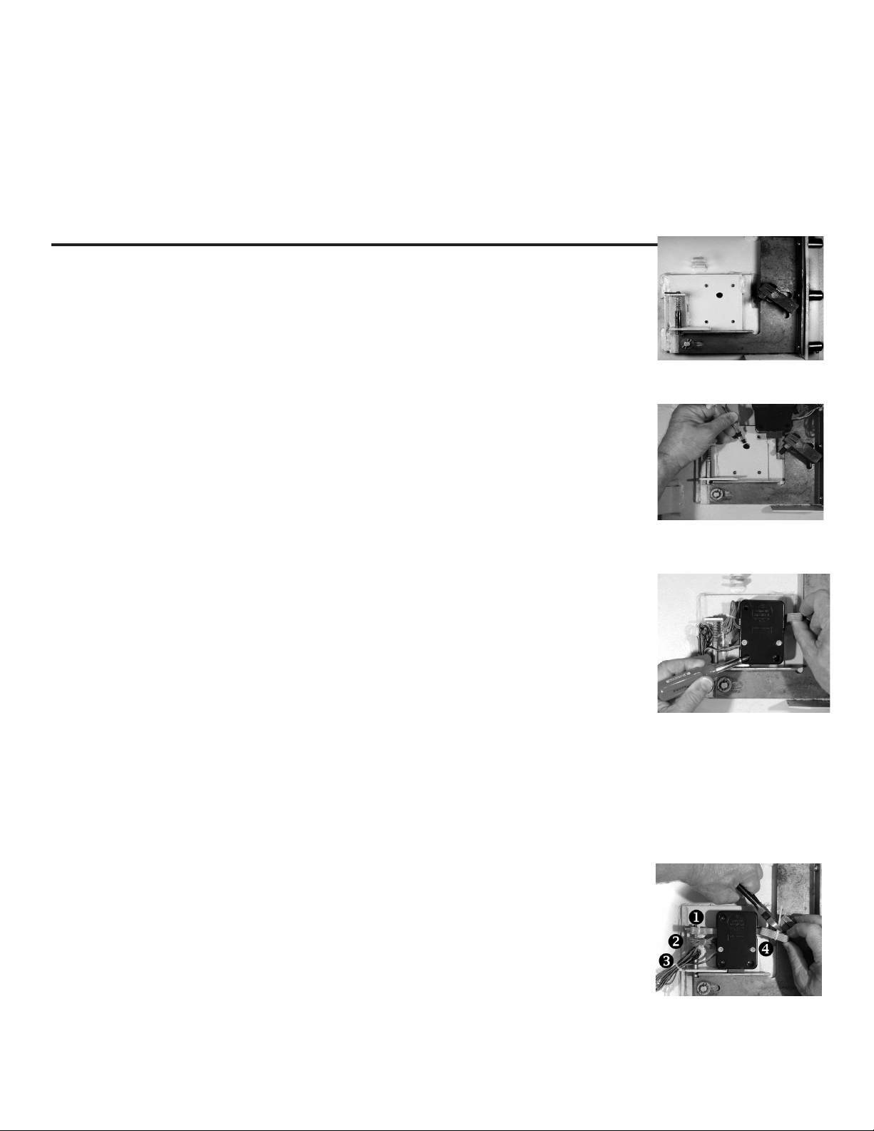
3. Usingtwoofthe¼-20(orM6)screwsinthekit,looselyattachthelockbodytothe
safe’smountingplate.isisjusttoholditinplaceduringcableattachmentstothe
keypadandkeypadextension.Beverycarefultoavoidcrushingorcrimpingthe
cables.Notetheblack/red/greenwirebundle.isisfortheboltpositionindicator,
adrycontactswitch(200VDC,0.5ampmax.)eblackwireiscommon,thegreen
wirecompletesacircuittotheblackwirewhenthelockboltisretracted,andthered
wirecompletesacircuittotheblackwirewhenthelockboltisextended.eBPI
canbeusedtotriggeranyswitch-activateddevice.
Notethebluewireloop.isisthesecureloop,aclosedcircuitthatmaybeusedin
applicationsrequiringswitchesorotherdevicestosignalthelockthatboltworkis
thrown,thedoorisclosed,orsomeotheractionhastakenplace.elockboltwill
NOTretractifthecircuitformedbythebluewireloopisopen.Bothsetsofwires
shouldbebundledandplacedwheretheywillnotinterferewithmovingboltwork
componentsifnotused.
4. Removethelockmountingscrewssoyoucancarefullypulltheexcessextension
basecableinside.Itisimportanttomakesurethekeypadandextensioncablesare
withintherecessedchannelsunderneaththelockcasebeforethecaseissecurely
attachedbythethreemountingscrews.Onceplacedinthemostconvenientchannel,
eachcableshouldbeprotectedunderneaththecasebyaself-adhesivefoamorvinyl
pad.Itisveryimportantthatcablesarenotfolded,crimped,orcrushedbeneaththe
lockcase.erearefoursetsofwiresthatmustbecarefullyplacedwheretheywill
notinterferewithorbedamagedbymovingboltwork.eseare:
• excesskeypadcable(4-conductor)
• secureloop(1-conductorbluewire)
• boltpositionindicator(BPI)wires
• excesskeypadextensioncable(5-conductor) 2

A. Makesurethelockboltdoesn’tbindagainstthesafe’sboltwork.etopphotoshowsbindingoftheedgeof
thecutoutinthesafe’sblockingbar,eventhoughtheboltworkisfullythrowntothelockedposition.Inthe
bottomphoto,thebindinghasbeenrelievedbyremovingasmallamountofmaterialfromthesideofthe
blockingbarcutout.Itisimportantthatthereisclearanceonallsidesofthelock’sboltwhentheboltworkis
inthefullylockedposition.Bindingwillimpairthelock’sperformance.Anynecessarymodicationsshould
bemadetotheboltwork,notthelock.
B. Ifyoursafeincorporatesarelockdevice,youwillneedtoattachtheplatethatnormallyholdsitincheckto
thelockbody.isisusuallydoneatthelock’scoverscrewlocations.Removethecoverscrews.DONOT
REMOVETHELOCKCOVER,asthiswillvoidtheproductwarranty.Typically,thecoverscrewswillbe
replacedwithslightlylonger8-32machinescrews.Yourreplacementscrewsmustengagethethreadedholes
inthelockbodybyatleastfourthreads.Relockdevicedesignsvaryfromsafetosafe.Youmustmakesure
thereplacementcoverscrewsholdthelockcoverrmlyagainstthelockbody,andthattherelockdevice
plateholdsthedevicesecurelyincheck.Otherwise,thereisriskofalockout.Aertheplateisinstalled,once
againchecktomakesurewiresandcablesaresecuredsothattheywillnotcomeintocontactwithmoving
boltworkoranythingelsethatcandamagethem.
Lock installation Considerations
IncorrrectCorrrect
3
Keypad and Keypad Extension Installation with Escutcheon
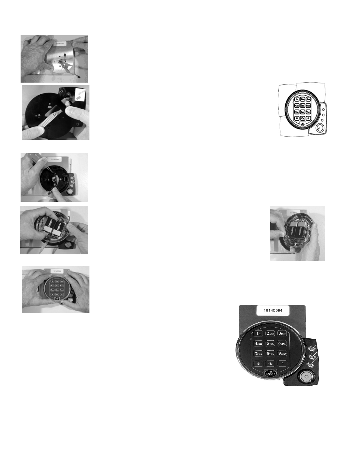
1. Cleanthefrontsurfaceofthesafedoorsothenumberplatewilladhere.Removetheclearprotective
lmfromthefrontoftheplate,andaxtheincludedserialnumberlabelasshown.Next,remove
theprotectivepaperbackingontheundersideoftheplate,thenrunbothcablesthroughthecenter
holeoftheplate.Placetheplateonthefrontofthesafe,carefullyliningupthemountingscrewholes
inthesafedoor.eplatewillstickinplacewhenpressedagainstthedoor.
2.
3. Placethekeypadbaseoverthekeypadextension,pullallexcesscablethroughthecenterhole(as
shown),lineupthekeypadbasemountingscrewholeswiththoseinthedoor,andusetheincluded
8-32(orM4)machinescrewstosecurelyfastenthemountingbasetothedoor.Itwillalsoholdthe
keypadextensionandnumberplate(ifused)rmlyinplace.eraised,circularpostneartheedge
ofthebasewillbeverynearthebottomofthekeypad.Usethisfeatureasareferencetohelpyou
orientthebasecorrectlybeforeyoufastenitintoplace.
4.
5. Placethekeypadoverthebase.Makesurethekeypadcableisclearofthepad’stwospringclips
asyoupushthekeypadrmlyontothebase.Itshouldsnapintoplace.Ifyouneedtoremovethe
keypad,pullthebottom(areanearesttheS&Glogo)awayfromthemountingbaserst.Neverallow
thekeypadtohangbytheattachedcable.einstallationiscomplete,butdonotclosethesafedoor
untilsuccessfullycompletingthefollowinglocktest.
einstallationiscomplete,butdonotclosethesafedooruntilsuccessfullycompleting
thefollowinglocktest.
efollowingcheckshouldbeperformedthreetimeswiththedoorremainingOPEN.
Atthekeypad,enter10101010#.elockwillBEEPthreetimesanditsboltwillretract.
Turnthesafehandletoverifythatthelockisunlocked.Turnthesafehandletothelocked
position.egreenSTATUS1LEDonthekeypadextensionwilllightbriey.e safe
door should remain open for the three operational checks.Youcanclosethesafedoor
andturnthehandletothelockedpositionaerthethirdoperationalcheck.elockbolt
willextend,andthelockwillBEEPthreetimes.Inaddition,thegreenSTATUS1LEDon
thekeypadextensionwilllightbriey.Testthesafe’shandletomakesureitissecure.
Lock Test
Fromthefrontofthesafe,connecttheve-conductorcable(thelarger
one)tothekeypadextensionbase.econnectorandreceptacleare
“keyed,”sotheconnectorwillonlyseatwhenorientedcorrectly.Route
thecableasshownhere.Makesuretheconnectorisfullyseatedinthe
keypadextensionreceptacle.Notetheself-adhesivepadtotherightofthe
cablereceptacle.Oncetheconnectorispluggedin,removetheprotective
backingfromthispad.Pullallexcesscablethroughthecenteropening
tothefrontoftheextensionbase.enlineupthebase’smountingscrew
holeswiththoseinthedoor,andpresstheextensionagainstthedoor.e
extensioncanbemountedinfourdierentorientations.Picktheonethat
bestsuitsyourparticularapplication.
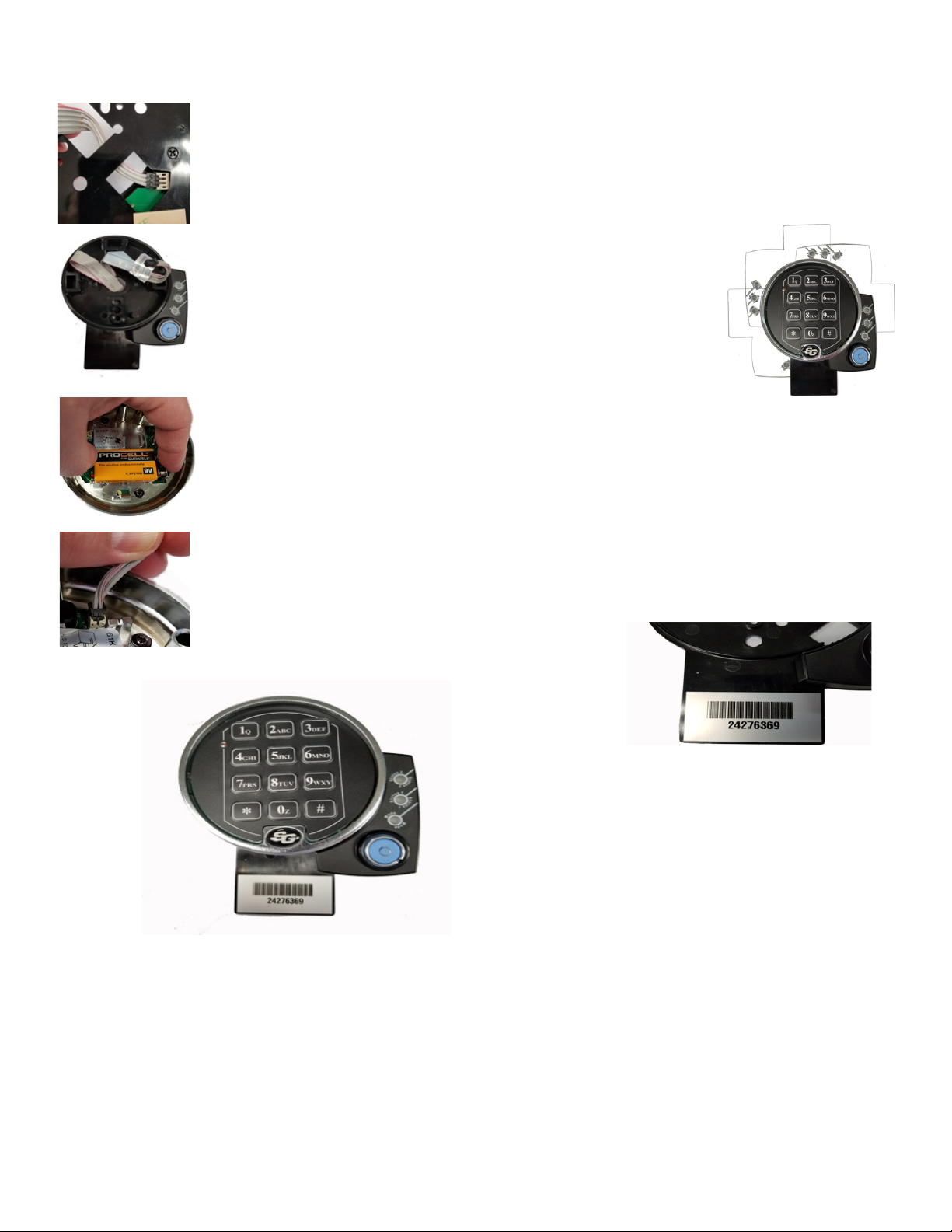
Atthefrontofthesafe,installanew9-voltbatteryineachofthekeypad’s
twobatteryholders.Duracell®brandbatteriesarerecommended.Support
thetopofeachholderwithathumborngeraseachbatteryisinserted.
iswillhelppreventbendingorbreakingtheholderposts.ekeypad
cableconnectorisshapedsothatitwilltintothekeypadreceptacle
onlywhenalignedcorrectly.Inserttheconnectorintothereceptaclein
theundersideofthekeypad.Ifitdoesnotseateasily,donotforceit.is
meansyouneedtoturnit1800beforeattemptingtoinsertitagain.
4
Sargent & Greenleaf, Inc.
One Security Dr.
Nicholasville, KY 40340-0930 USA
Phone: (800)-826-7652
Fax: (800)-634-4843 5
Sargent & Greenleaf S.A.
9, Chemin du Croset
1024 Ecublens, Switzerland
Phone: +41-21 694 34 00
Fax: +41-21 694 34 09
Document 630-821
Revised 03/18/2019
Placethekeypadbaseoverthekeypadextension,pullallexcesscable
throughthecenterhole(asshown),lineupthekeypadbasemountingscrew
holeswiththoseinthedoor,andusetheincluded8-32(orM4)machinescrews
tosecurelyfastenthemountingbasetothedoor.Itwillalsoholdthekeypad
extensionandnumberplate(ifused)rmlyinplace.eraised,circularpost
neartheedgeofthebasewillbeverynearthebottomofthekeypad.Usethis
featureasareferencetohelpyouorientthebasecorrectlybeforeyoufastenit
intoplace.eextensioncanbemountedinfourdierentorientations.Pickthe
onethatbestsuitsyourparticularapplication.
efollowingcheckshouldbeperformedthreetimeswiththedoorremainingOPEN.
Atthekeypad,enter10101010#.elockwillBEEPthreetimesanditsboltwillretract.Turnthesafehandletoverifythatthelockisunlocked.Turn
thesafehandletothelockedposition.egreenSTATUS1LEDonthekeypadextensionwilllightbriey.esafedoorshouldremainopenforthe
threeoperationalchecks.Youcanclosethesafedoorandturnthehandletothelockedpositionaerthethirdoperationalcheck.elockboltwill
extend,andthelockwillBEEPthreetimes.Inaddition,thegreenSTATUS1LEDonthekeypadextensionwilllightbriey.Testthesafe’shandleto
makesureitissecurely
1. Fromthefrontofthesafe,connecttheve-conductorcable(thelargerone)tothekeypadextensionbase.
econnectorandreceptacleare“keyed,”sotheconnectorwillonlyseatwhenorientedcorrectly.Routethe
cableasshownhere.Makesuretheconnectorisfullyseatedinthekeypadextensionreceptacle.Notethe
self-adhesivepadtotherightofthecablereceptacle.Oncetheconnectorispluggedin,removetheprotec-
tivebackingfromthispad.Pullallexcesscablethroughthecenteropeningtothefrontoftheextension
base.enlineupthebase’smountingscrewholeswiththoseinthedoor,andpresstheextensionagainst
thedoor.
2.
3. Atthefrontofthesafe,installanew9-voltbatteryineachofthekeypad’stwobatteryholders.Duracell®
brandbatteriesarerecommended.Supportthetopofeachholderwithathumborngeraseachbatteryis
inserted.iswillhelppreventbendingorbreakingtheholderposts.
4. ekeypadcableconnectorisshapedsothatitwilltintothekeypadreceptacleonlywhenalignedcor-
rectly.Inserttheconnectorintothereceptacleintheundersideofthekeypad.Ifitdoesnotseateasily,do
notforceit.ismeansyouneedtoturnit1800beforeattemptingtoinsertitagain.
5. Placethekeypadoverthebase.Makesurethekeypadcableisclearofthepad’stwospringclipsasyoupush
thekeypadrmlyontothebase.Itshouldsnapintoplace.Ifyouneedtoremovethekeypad,pullthebottom
(areanearesttheS&Glogo)awayfromthemountingbaserst.Neverallowthekeypadtohangbytheat-
tachedcable.
6. AttachthelockSerialnumbertotheKeypadExtensionplate.
Keypad and Keypad Extension Installation
einstallationiscomplete,butdonotclosethesafedooruntil
successfullycompletingthefollowinglocktest.
Lock Test
Table of contents
Other SG Lock manuals


Popular Lock manuals by other brands


nimly
nimly Code installation guide

Abus
Abus FTS 3003 Fitting and operating instruction

Hammond Manufacturing
Hammond Manufacturing HMEHSKL Series Assembly instructions

Spectrum Brands
Spectrum Brands Kwikset 258SQT 11P SMT installation guide

Kaba Mas
Kaba Mas Unicon CL20 installation instructions

Kensington
Kensington ComboSaver Instruction guide