SGC PowerTalk Head w/ADSP & SNS 04-22 User manual

PowerTalk™ Manual
SGC Inc. SGC Building, 13737 S.E. 26th St. P.O.Box 3526, Bellevue, WA. 98009 USA
Fax: 206-746-6384 • Tel: 206-746-6310 • 1-800-259-7331
© 1994 SGC, Inc.
June28,2004;15:46
SG-2000
PowerTalkTM
Headw/ADSPTM &
SNSTM
(Catalog Number 04-22)
For the SG-2000 HF SSB
Installation and Operations Manual
Revised: Sept. 6, 1995

PowerTalk™ Manual i
SGC Inc. SGC Building, 13737 S.E. 26th St. P.O.Box 3526, Bellevue, WA. 98009 USA
Fax: 206-746-6384 • Tel: 206-746-6310 • 1-800-259-7331
© 1994 SGC, Inc.
June28,2004;15:46
Table of Contents
Section Page
1.0 General Description ...............................................................................................1
2.0 Noise Reduction ...................................................................................................2
2.1 Adaptive Digital Signal Processing .........................................................................2
2.2 Spectral Noise Subtraction (SNS™) .....................................................................2
2.3 ADSP™ ...............................................................................................................3
2.4 Notch Filter ..........................................................................................................3
2.5 High, Low and Center Frequency Filters ................................................................4
3.0 Front Panel Layout ................................................................................................5
4.0 ADSP™ Control Panel Layout .............................................................................6
4.1 Notch Filter (NOTCH) .........................................................................................6
4.2 Bandpass Filter .....................................................................................................7
4.2.1 Low Frequency Corner .........................................................................................7
4.2.2 High Frequency Corner .........................................................................................8
4.2.3 Center Frequency .................................................................................................9
4.3 Noise Reduction (NOISE) ....................................................................................10
4.4 Spectral Noise Subtraction (SNS™) .....................................................................11
4.5 Preset Memory (PRESET) ....................................................................................12
4.6 User Memory .......................................................................................................13
4.7 Bypass (BYPASS) .............................................................................................14
4.8 Digital Rotary Control (ADJ) .................................................................................15
4.9 LED Display .........................................................................................................15
4.9.1 "Off" Condition .....................................................................................................15
4.9.2 "On" Condition ......................................................................................................15
4.10 Mnemonics ...........................................................................................................16
4.10.1 Memory Selection .................................................................................................16
4.10.2 Preset Memory Function .......................................................................................17
4.10.3 Operating Functions ..............................................................................................17
4.11 Toggling Between Bandpass and User ...................................................................17
4.12 Conclusion ............................................................................................................18
5.0 Key Pad Changes .................................................................................................19
5.1 Keys Deleted ........................................................................................................19
5.2 Keys Modified ......................................................................................................20
5.3. Keys Added...........................................................................................................20
5.4 Modes of Operation ..............................................................................................21
5.5 Operational Changes with Tuning Knob...................................................................22
6.0 Operating the PowerTalk™ ..................................................................................24
6.1 Key Functions.........................................................................................................24
6.2 Sample Entries........................................................................................................28
7.0 Display LCD .........................................................................................................30

PowerTalk™ Manual ii
SGC Inc. SGC Building, 13737 S.E. 26th St. P.O.Box 3526, Bellevue, WA. 98009 USA
Fax: 206-746-6384 • Tel: 206-746-6310 • 1-800-259-7331
© 1994 SGC, Inc.
June28,2004;15:46
8.0 Front Panel Controls ...............................................................................................33
8.1 Primary Keyboard Functions .................................................................................33
8.2 SHIFT Functions ..................................................................................................40
8.3 Program Functions ..................................................................................................41
8.4 Operating Session .................................................................................................42
8.6 Scanning Functions ................................................................................................48
8.7 Changing Frequency...............................................................................................52
8.8 Additional Functions................................................................................................54
9.0 Schematics..............................................................................................................60
10.0 Index ....................................................................................................................66

PowerTalk™ Manual iii
SGC Inc. SGC Building, 13737 S.E. 26th St. P.O.Box 3526, Bellevue, WA. 98009 USA
Fax: 206-746-6384 • Tel: 206-746-6310 • 1-800-259-7331
© 1994 SGC, Inc.
June28,2004;15:46
Disclaimer
The "ADJ" knob has a mechanical detent. You can feel
the detents when the ADJ knob is rotated. The
ADSP™ portion of the PowerTalk™ head can hang up
if the ADJ knob stops between detents. Rotating the
ADJ knob and stopping on the detent will allow the
head to adjust properly.

PowerTalk™ Manual 1
SGC Inc. SGC Building, 13737 S.E. 26th St. P.O.Box 3526, Bellevue, WA. 98009 USA
Fax: 206-746-6384 • Tel: 206-746-6310 • 1-800-259-7331
© 1994 SGC, Inc.
June28,2004;15:46
1.0 General Description
Since the PowerTalk™ head is only one of the several optional heads for the SG-2000
HF SSB radio, this manual is designed as a companion to the manual for the SG-2000.
There is much vital information on such things as antenna and grounding setups,
licenses needed, computer control of the radio, software and hardware accessories and
troubleshooting in the SG-2000 manual that is beyond the scope of this manual.
This manual will tell you how to operate the PowerTalk™ Head. If you have just
bought the SG-2000 radio with the PowerTalk™ head, please read the SG-2000 manual
to make sure you have properly set up the radio before you start reading this manual.
If you have bought this head separately to install on an existing SG-2000 setup and are
happy with the performance of the system, this manual will tell you how to get the
most from the PowerTalk™ head. If you think the performance of your radio could be
better, you might want to look at the SG-2000 manual again and follow some of its
suggestions for optimal performance.

PowerTalk™ Manual 2
SGC Inc. SGC Building, 13737 S.E. 26th St. P.O.Box 3526, Bellevue, WA. 98009 USA
Fax: 206-746-6384 • Tel: 206-746-6310 • 1-800-259-7331
© 1994 SGC, Inc.
June28,2004;15:46
2.0 Noise Reduction
The PowerTalk™ head incorporates several technologically advanced processes to
filter out unwanted received noise, resulting in dramatically enhanced signal clarity.
Adaptive Digital Signal Processing (ADSP™), Spectral Noise Subtraction (SNS™) and
the Notch filter (tone suppressor) are three methods used by the PowerTalk™ head to
filter out signal noise. In addition, the user can adjust the quality of the audio signal by
setting the Low, High and Center frequency. These processes can be used separately or
in combination by the user to configure the audio to get the best possible reception.
2.1 Adaptive Digital Signal Processing (ADSP™)
The benefit of ADSPTM is illustrated in the following graph:
2.2 Spectral Noise Subtraction (SNS™)
The benefit of SNS™ is illustrated by the following graph:

PowerTalk™ Manual 3
SGC Inc. SGC Building, 13737 S.E. 26th St. P.O.Box 3526, Bellevue, WA. 98009 USA
Fax: 206-746-6384 • Tel: 206-746-6310 • 1-800-259-7331
© 1994 SGC, Inc.
June28,2004;15:46
2.3 ADSP™ and SNS™
The benefit of ADSP™ and SNS™ working in tandem is even more dramatic as
illustrated in the following graph:
2.4 Notch Filter
If the PowerTalk™ head detects the presence of any constant tones, enabling the
Notch filter will suppress this tone by 40 dB. The Notch filter will automatically
suppress up to 5 tones at once.

PowerTalk™ Manual 4
SGC Inc. SGC Building, 13737 S.E. 26th St. P.O.Box 3526, Bellevue, WA. 98009 USA
Fax: 206-746-6384 • Tel: 206-746-6310 • 1-800-259-7331
© 1994 SGC, Inc.
June28,2004;15:46
2.5 High, Low and Center Frequency Filters
In addition to the above noise reduction features, which are mainly on or off, the
PowerTalk™ head lets the user adjust the audio quality to their own liking by
means of the High, Low and Center Frequency filters as illustrated below:

PowerTalk™ Manual 5
SGC Inc. SGC Building, 13737 S.E. 26th St. P.O.Box 3526, Bellevue, WA. 98009 USA
Fax: 206-746-6384 • Tel: 206-746-6310 • 1-800-259-7331
© 1994 SGC, Inc.
June28,2004;15:46
3.0 Front Panel Layout
The front panel of the PowerTalk™ head is shown in Figure 1 below. While the basic
display and many of the button functions are similar to the Standard SG-2000 head,
there are enough differences and new capabilities to warrant giving the PowerTalk™
its own manual.
Figure 1
The main visible differences in the new PowerTalk™ head are the ADSP™ control
section in the upper left corner, the tuning knob in the lower left corner that replace the
up and down arrows of the standard head, and associated buttons. The following
sections of this manual, detailing the operations of the PowerTalk™ head, will refer to
this drawing.
PowerTalk™ Manual 6
SGC Inc. SGC Building, 13737 S.E. 26th St. P.O.Box 3526, Bellevue, WA. 98009 USA
Fax: 206-746-6384 • Tel: 206-746-6310 • 1-800-259-7331
© 1994 SGC, Inc.
June28,2004;15:46
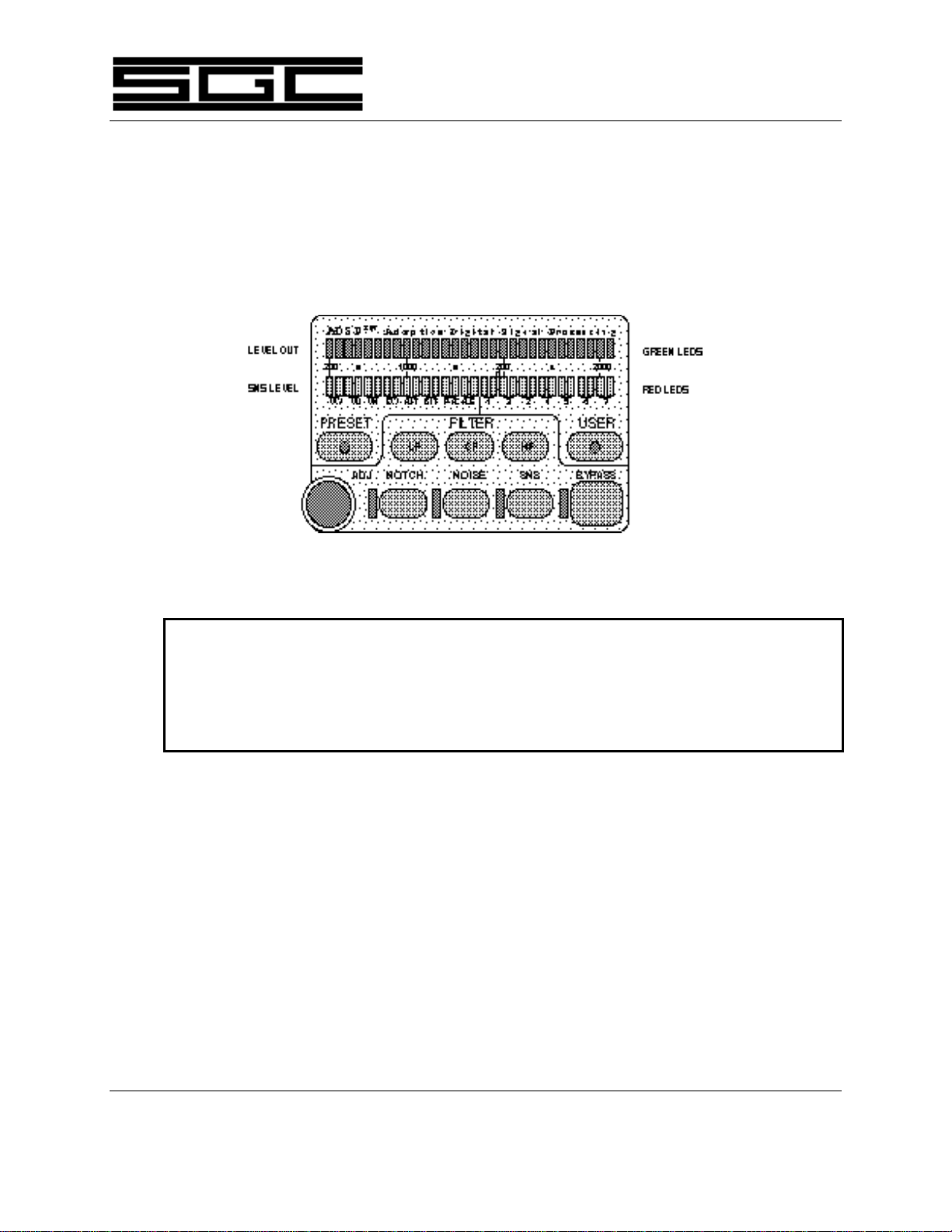
4.0 ADSP™ Control Panel Layout
Let's start with the section that gives the PowerTalk™ its reason for being: the ADSPTM
(Adaptive Digital Signal Processing) control panel in the upper left corner of the
PowerTalk™ face. The overall panel layout is shown below in Figure Two:
Figure Two
Disclaimer:
The "ADJ" knob has a mechanical detent. You can feel the detents when the ADJ knob is
rotated. The ADSP™ portion of the PowerTalk™ head can hang up if the ADJ knob stops
between detents. Rotating the ADJ knob and stopping on the detent will allow the head to
adjust properly
Now lets go over the operation and control of the ADSP™ control panel step by step.
4.1 Notch Filter (NOTCH)
The PowerTalk™ head has the ablility to sense and suppress up to five (5) tones
simultaneously. When the NOTCH push-button is selected, the green LED next
to it will illuminate. Tones will be rejected in the 0-4,000 Hz. frequency band.
(See Figure Three).

PowerTalk™ Manual 7
SGC Inc. SGC Building, 13737 S.E. 26th St. P.O.Box 3526, Bellevue, WA. 98009 USA
Fax: 206-746-6384 • Tel: 206-746-6310 • 1-800-259-7331
© 1994 SGC, Inc.
June28,2004;15:46
Figure Three
The noise reduction benefit of the Notch Filter is shown in the graph below,
reproduced from Section 2.4:
4.2 Bandpass Filter
Band Pass functionality is achieved by separately adjusting the lower and higher
bandpass corner frequencies in 100 Hz increments and moving the filter's center
frequency across the available bandwidth. Displayed frequencies are between
200 and 3100 Hz. The lower frequency limit, however, can be as small as 100 Hz.
Adjustments are made through the digital rotary control—labeled "ADJ"—on the
ADSPTM panel.
4.2.1 Low Frequency Corner (LF)
The low corner frequency is selected by the LF push-button. The default
setting is 200 Hz. with the first red LED and the last 29 green LEDs
illuminated. Positioning of the lower corner frequency is set by the rotary
control. (See Figure Four).

PowerTalk™ Manual 8
SGC Inc. SGC Building, 13737 S.E. 26th St. P.O.Box 3526, Bellevue, WA. 98009 USA
Fax: 206-746-6384 • Tel: 206-746-6310 • 1-800-259-7331
© 1994 SGC, Inc.
June28,2004;15:46
Figure Four
A graphic representation of setting the Low Corner Frequency is shown
below, reproduced from Section 2.5:
4.2.2 High Frequency Corner (HF)
This filter is selected by the HF push-button. Default setting for this filter
is 3100 Hz. with the first 29 green LEDs and the last, or 30th, red LED
illuminated. Positioning of the Higher Corner Frequency is controlled by
the digital rotary control. (See Figure Five).

PowerTalk™ Manual 9
SGC Inc. SGC Building, 13737 S.E. 26th St. P.O.Box 3526, Bellevue, WA. 98009 USA
Fax: 206-746-6384 • Tel: 206-746-6310 • 1-800-259-7331
© 1994 SGC, Inc.
June28,2004;15:46
Figure Five
A graphic representation of setting the High Corner Frequency is shown
below, reproduced from section 2.5:
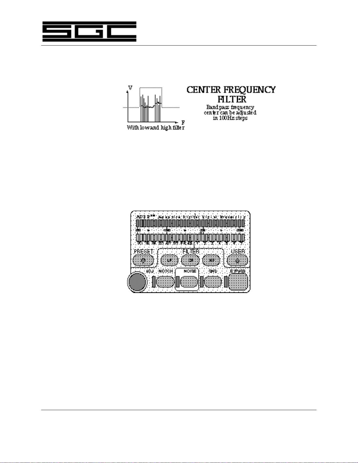
4.2.3 Center Frequency (CF)
Once the operator has chosen the Bandpass Filter's range by means of the
Upper and Lower Corner Frequencies, the Center Frequency can be
selected by pressing the CF push-button. When selected, all green LEDs
within the passband range will be illuminated. In addition, within five
seconds of pressing the CF push-button, the operator may begin adjusting
the Center Frequency up or down via the digital rotary control. (See
Figure Six).
Figure Six
PowerTalk™ Manual 10
SGC Inc. SGC Building, 13737 S.E. 26th St. P.O.Box 3526, Bellevue, WA. 98009 USA
Fax: 206-746-6384 • Tel: 206-746-6310 • 1-800-259-7331
© 1994 SGC, Inc.
June28,2004;15:46
A graphic representation of the Center Frequency Filter is shown below,
reproduced from section 2.5:
4.3 Noise Reduction (NOISE)
Noise reduction (shown below in the ADSP™ graph) is obtained via a digital
process which is initiated by pressing the NOISE push-button. When selected,
the green LED next to the NOISE push-button illuminates. (See Figure Seven).
Figure Seven

PowerTalk™ Manual 11
SGC Inc. SGC Building, 13737 S.E. 26th St. P.O.Box 3526, Bellevue, WA. 98009 USA
Fax: 206-746-6384 • Tel: 206-746-6310 • 1-800-259-7331
© 1994 SGC, Inc.
June28,2004;15:46
The noise reduction benefit ofthe Noise button is illustrated in the graph below,
reproduced from section 2.1:
4.4 Spectral Noise Subtraction (SNSTM)
Spectral Noise Subtraction is the special process of subtracting noise and that
portion of the spectrum where voice modulation is not used. It is selected by
pushing the SNSTM push-button. When selected, the LED next to the SNSTM
push-button illuminates. (See Figure Eight).
Figure Eight

PowerTalk™ Manual 12
SGC Inc. SGC Building, 13737 S.E. 26th St. P.O.Box 3526, Bellevue, WA. 98009 USA
Fax: 206-746-6384 • Tel: 206-746-6310 • 1-800-259-7331
© 1994 SGC, Inc.
June28,2004;15:46
The benefit of Spectral Noise Subtraction is illustrated in the graph below,
reproduced from Section 2.2:
4.5 Preset Memory (PRESET)
Eight options are preset into the unit's memory. These are:
VOICE BANDWIDTH NOTCH NOISE SNSTM
VW Wide (300 to 3100 Hz.) Yes Yes Yes
VM Medium (300 to 2000 Hz.) Yes Yes No
VN Narrow (300 to 1700 Hz.) Yes Yes No
CW Filter on 1000 Hz. ± 200 Hz. No Yes No
DATA BANDWIDTH
AMTOR Filter on 2175 Hz. ± 150 Hz.
SITOR Filter on 1700 Hz. ± 150 Hz.
PACTOR Filter on 2175 Hz. ± 200 Hz.
ALE Filter on 1725 Hz. ± 1125 Hz.
Two digital filters are used in the eight PRESET functions. For voice and CW
functions, a filter with a shape factor of 1:1 (130 ms delay) is used. The low ,
center and high frequency points of this filter can be adjusted to reduce adjacent
channel interference.
For data modes, the 130 ms delay of the voice/CW filter prevents a proper
handshake in ARQ modes and other data protocols due to increased switching
time between transmit and receive. Therefore, in the case of AMTOR, SITOR,
PACKET, PACTOR, G-TOR , and ALE, a second, very short, delay filter

PowerTalk™ Manual 13
SGC Inc. SGC Building, 13737 S.E. 26th St. P.O.Box 3526, Bellevue, WA. 98009 USA
Fax: 206-746-6384 • Tel: 206-746-6310 • 1-800-259-7331
© 1994 SGC, Inc.
June28,2004;15:46
(approximately 2 ms) is selected. This filter's shape factor is 1.15:1, and its
extremely steep skirts reject interference from adjacent frequencies.
Of necessity, the low, center and high frequency settings of data filter memories
are fixed. However, by transferring data memory parameters in PRESET mode to
USER mode, the short delay filter can be accessed and used in conjunction with
new parameters defined by the user and stored in a USER memory.
For information on transferring data memory parameters, see Section 4.6.
Selecting the PRESET function activates the last-used preset memory and causes
the two red LEDs above the selected function to become illuminated. The
digital rotary control can then be used to change to any of the eight preset
locations. (See Figure Nine).
Figure Nine
4.6 User Memory (USER)
Seven locations are provided for user-programmed memories. Pressing the
USER push-button activates the last-used User Memory selection and displays it
by illuminating the two LEDs above that position. If no memory has been
programmed into a particular User Memory location, the two LEDs above it will
be blinking. If a User Memory location has already been programmed, the LEDs
are on continuously. Use the rotary control to move between USER locations.

PowerTalk™ Manual 14
SGC Inc. SGC Building, 13737 S.E. 26th St. P.O.Box 3526, Bellevue, WA. 98009 USA
Fax: 206-746-6384 • Tel: 206-746-6310 • 1-800-259-7331
© 1994 SGC, Inc.
June28,2004;15:46
To program a user-defined memory, configure the ADSPTM section as desired
(frequency, mode, etc.) and choose an empty memory location. Then press and
hold the USER switch for six seconds. The LED pair above the location chosen
changes from blinking (empty) to being on steadily (programmed). To clear a
user-defined memory, depress the USER push-button and select the memory
location in question with the digital rotary control. Then press and hold the
USER button for six seconds. When the associated LED pair changes from being
on continuously to blinking, release the USER switch. The memory and its old
program have now been successfully cleared.
Figure Ten
By the same process, a Preset Memory location can be selected, modified and
then entered into a User Memory location.
4.7 Bypass (BYPASS)
The BYPASS push-button is a toggle that determines whether or not the ADSPTM
system is active. When BYPASS is pressed, its associated LED is illuminated
and all functions of the ADSP™ are disabled, or bypassed. If BYPASS is pushed
again or any ADSPTM function is selected (PRESET, USER, NOTCH, NOISE,
SNSTM, LF, CF or HF), ADSP™ becomes active again and the green LED
associated with the BYPASS button goes off, confirming that the ADSPTM system
is engaged and operating. Pushing the BYPASS button to re-engage the ADSP™

PowerTalk™ Manual 15
SGC Inc. SGC Building, 13737 S.E. 26th St. P.O.Box 3526, Bellevue, WA. 98009 USA
Fax: 206-746-6384 • Tel: 206-746-6310 • 1-800-259-7331
© 1994 SGC, Inc.
June28,2004;15:46
system will return the unit to the previous ADSP™ function while pushing any
other button will engage that particular function (See Figure Eleven).
Figure Eleven
4.8 Digital Rotary Control (ADJ)
The digital rotary control affects ADSPTM functions as follows:
Preset Memory (PRESET) Set Location
User Memory (USER) Set Location
Spectral Noise Subtraction (SNSTM)Set Level
Low Frequency Corner Filter (LF) Set Frequency
High Frequency Corner Filter (HF) Set Frequency
Center Frequency Filter (CF) Adjusts Frequency Center
4.9 LED Display
4.9.1 "Off" Condition
When the unit is in bypass mode, all LED indicators, except BYPASS,
including dedicated LEDs, i.e., NOTCH, NOISE and SNSTM are off.
4.9.2 "On" Condition
Appropriate dedicated LEDs are on. NOTCH, NOISE , SNSTM and
BYPASS have dedicated LEDs.

PowerTalk™ Manual 16
SGC Inc. SGC Building, 13737 S.E. 26th St. P.O.Box 3526, Bellevue, WA. 98009 USA
Fax: 206-746-6384 • Tel: 206-746-6310 • 1-800-259-7331
© 1994 SGC, Inc.
June28,2004;15:46
When selected, the PRESET Memory or USER Memory functions will
cause the LED pair associated with the last-used memory location to
illuminate and blink if empty or stay on continuously if already
programmed.
If NOISE is selected, the adjacent LED is illuminated.
If SNSTM is selected, the adjacent LED is illuminated and the row of red
LEDs -labeled "SNSTM LEVEL" on Figure One -is used as a spectral noise
subtraction, peak-reading meter.
If LF, CF, or HF buttons are depressed, the lower corner frequency, the
upper corner frequency and/or the bandwidth frequencies outside the
passband are indicated by red LEDs. The selected corner or center
frequency can be set by the ADJ (for ADJUST) knob. When bandpass is
activated, both green and red LED displays change to VU-type metering
within five seconds. When either the PRESET or USER memory function
buttons are depressed, the LED memory pair of the specific memory
selected will be displayed. If NOISE , SNSTM , NOTCH, LF, CF or HF is
selected, the display will change to VU metering.
4.10 Mnemonics
4.10.1 Memory Selection
Preset Memory PRESET Section 4.5
User Memory USER Section 4.6
Table of contents
Other SGC Transceiver manuals


