CMOSTEK CMT2300A User manual

AN199
Rev0.7 | 1/8
www.cmostek.com
Overview
This document discusses the RF frequency calculation formula for CMT2300A / CMT2119B / CMT2219B, which helps on further
design and application based on the products.
The product models covered in this document are shown in the below table.
Table 1. Product Models Covered in This Document
Product Model
Frequency Range
Modulation Type
Main Function
Configuration Mode
Packaging
CMT2300A
126.33 - 1020 MHz
(G)FSK/OOK
Transceiver
Register
QFN16
CMT2119B
126.33 - 1020 MHz
(G)FSK/OOK
Transmitter
Register
QFN16
CMT2219B
126.33 - 1020 MHz
(G)FSK/OOK
Receiver
Register
QFN16
Before reading this document, it is recommended to read the AN142-CMT2300A Quick Start Guide, AN184-CMT2119B Quick
Start Guide and AN161-CMT2219B Quick Start Guide to understand the basic information of the 3 products.
AN199
CMT2300A/CMT2119B/CMT2219B RF Frequency Calculation Guide
Copyright © By CMOSTEK

AN199
Rev0.7 | 2/8
www.cmostek.com
Table of Contents
1RF Frequency Calculation.................................................................................................................3
1.1 Configuring RF Parameters of RX...................................................................................................................... 3
1.2 Configuring RF Parameters of TX ......................................................................................................................6
2Revise History ....................................................................................................................................7
3Contacts..............................................................................................................................................8

AN199
Rev0.7 | 3/8
www.cmostek.com
1 RF Frequency Calculation
The RF frequency calculation and manual configuration methods for the 3 products are described below. Note that the
description of RXpart isnot applicable to the CMT2119B and the statement of TXpart isnot applicable to the CMT2219B.
In general, when configuring RF frequency, it's recommended for users to generate parameters using RFPDK and write them to
the registers in the frequency area. If users need to configure the frequency of TX and RX separately in applications while not
using the fast frequency hopping mechanism, it's required for users to know the detail information of the register configuration
and related value calculation. The registers in the frequency area are listed in thebelow table.
Table 2. Registers in Frequency Area
In the table, the value of FSK_SWT is generated by RFPDK, with no depending on frequency. Do not change this value when
configuring other bits of the register.
1.1 Configuring RF Parameters of RX
To configure the frequency of RX, the below items need to be configured.
FREQ_VCO_BANK <2:0>
FREQ_DIVX_CODE <2:0>
FREQ_RX_N <7:0>
FREQ_RX_K <19:0>
AFC_OVF_TH <7:0>
Among them, N is the integer part of the frequency word, K is the fractional part of the frequency word, DIVX CODE is used to
select the division factor of the PLL, and VCO BANK is used to select the operating frequency range of the VCO. The calculation
is as follows.
First, check the table to get the value of FREQ_VCO_BANK<2:0> and FREQ_DIVX_CODE<2:0> (both need to be written to the
registers) and DIVIDER (frequency dividing factor, used to calculate N and K) according to the target frequency band where the
configured frequency is located.
Addr R/W Name Bit 7 Bit 6 Bit 5 Bit 4 Bit 3 Bit 2 Bit 1 Bit 0 Function
0x18 RW CUS_RF1
0x19 RW CUS_RF2
0x1A RW CUS_RF3
0x1B RW CUS_RF4 FREQ_PALDO_SEL
0x1C RW CUS_RF5
0x1D RW CUS_RF6
0x1E RW CUS_RF7
0x1F RW CUS_RF8 FSK_SWT
频率区
FREQ_TX_N [7:0]
FREQ_TX_K [7:0]
FREQ_TX_K [15:8]
FREQ_VCO_BANK [2:0] (000)
FREQ_TX_K [19:16]
FREQ_RX_N [7:0]
FREQ_RX_K [7:0]
FREQ_RX_K [15:8]
FREQ_DIVX_CODE [2:0]
FREQ_RX_K [19:16]
Frequency Area

AN199
Rev0.7 | 4/8
www.cmostek.com
Table 3. Correspondence between PLL Analysis Parameters and Target Frequencies
Target Frequency Band
FREQ_DIVX_CODE <2:0>
DIVIDER
FREQ_VCO_BANK<2:0> = 110
FREQ_VCO_BANK<2:0> = 001
758 –840 MHz
840 –1020 MHz
000
2
379 –420 MHz
420 –510 MHz
001
4
189.5 –210 MHz
210 –255 MHz
010
8
126.33 –140 MHz
140 –170 MHz
011
12
252.67 –280 MHz
280 –340 MHz
101
6
Then calculate the frequency of the LO (local oscillator). In the formula below, FREQ_RF is the target RF frequency in MHz.
FREQ_LO is the calculated local oscillator frequency in Hz.
FREQ_LO = FREQ_RF x 10^6 + 26 MHz/92
Then calculate the value of the frequency word N.K.
N.K = FREQ_LO x DIVIDER / 26 MHz
Obtain the integer part of N.K and convert it to binary, which is the value of FREQ_RX_N <7:0>. The fractional part is multiplied
by 2^20 and rounded off,which is the value of the register FREQ_RX_K <19:0>.
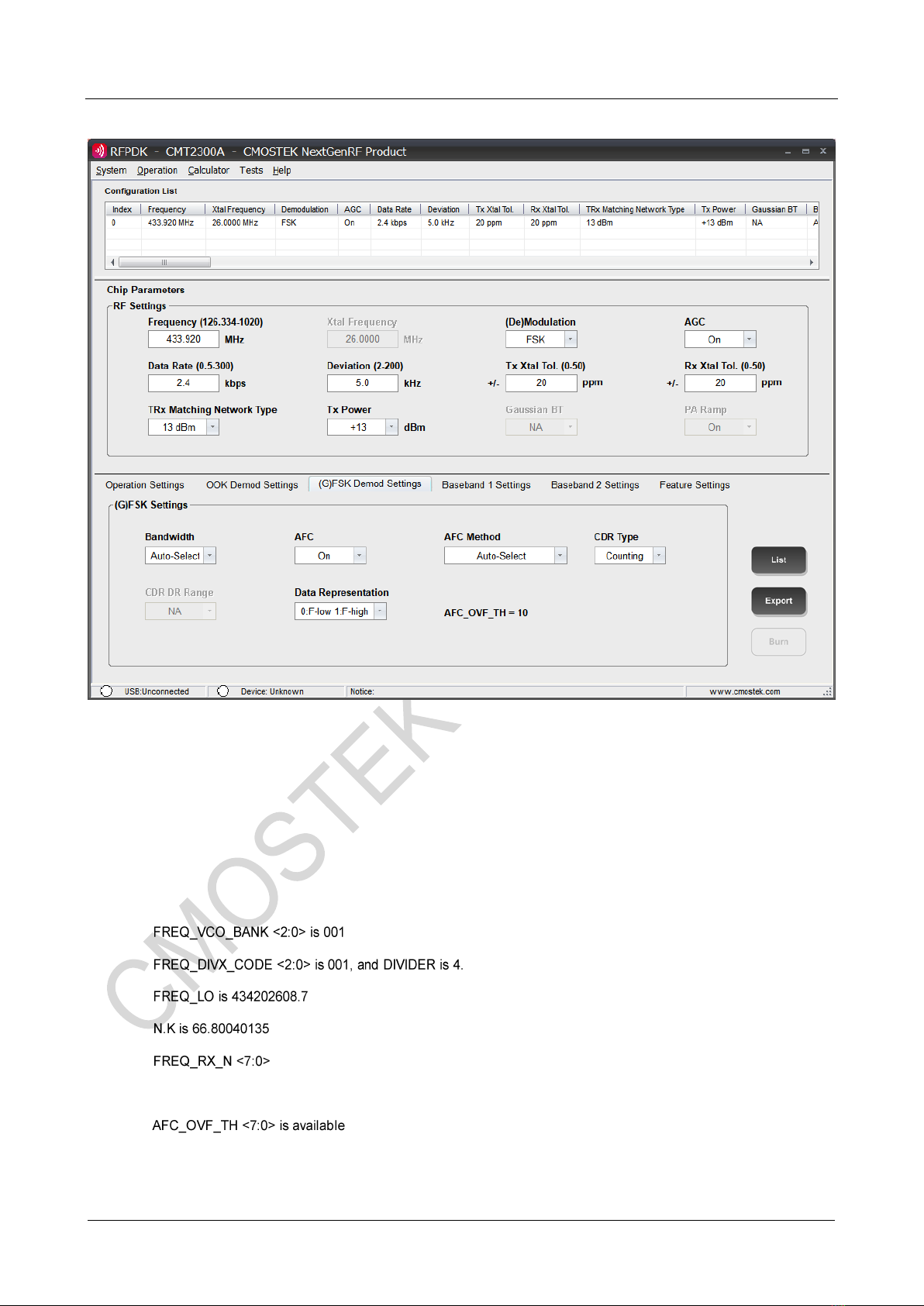
The last step is to get the value of AFC_OVF_TH <7:0>. This register is not in the frequency area. As an key parameter of the
receiver AFC algorithm, it is calculated based on such parameters of receivers as RX RF frequency, data rate, deviation, and
crystal PPM. When the calculation completes, the result displays on the RFPDK screen as shown in the below figure.
AN199
Rev0.7 | 5/8
www.cmostek.com
Figure 1. AFC_OVF_TH Screen of RFPDK
Users need to fill in the desired RF frequency of RX for manual configure in RFPDK, then get the value of AFC_OVF_TH <7:0>.
As the last step, fill it into the register with an address of 0x27 CUS_FSK4 to make the receiver work normally, otherwise the
receiver may have error when performing AFC, which may cause receiving failure.
For example, if the target RF frequency for RX to be configured is 433.92 MHz, according to the above calculation, it can obtain
the followings.
.
.
.
is 66 and the corresponding binary is 01000010.
FREQ_RX_K <19:0> is 839282 and the corresponding binaryis 11001100111001110010.
in RFPDK.

AN199
Rev0.7 | 6/8
www.cmostek.com
1.2 Configuring RF Parameters of TX
Followingsneed to be configured for TX.
FREQ_VCO_BANK <2:0>
FREQ_DIVX_CODE <2:0>
FREQ_TX_N <7:0>
FREQ_TX_K <19:0>
FREQ_PALDO_SEL
Among them, FREQ_VCO_BANK<2:0> and FREQ_DIVX_CODE <2:0> are obtained in the same way as in RX, that is, TX and
RX share DIVX CODE and VCO BANK. If the target frequency bands are not the same, when each time TX or RX is configured,
recalculation and writing to these two registers isneeded.
Then calculate the frequency of the LO (local oscillator), which is different from the LO frequency of RX. In the formula below,
FREQ_RF is the target RF frequency in MHz. FREQ_LO is the calculated local oscillator frequency in Hz.
FREQ_LO = FREQ_RF x 10^6
Then calculate the value of the frequency word N.K, which is the same as the N.K value calculation formula for RX:
N.K = FREQ_LO x DIVIDER / 26 MHz
At last, check the table below to get the value of FREQ_PALDO_SEL:
TX Frequency
FREQ_PALDO_SEL
< 500 MHz
0
>= 500 MHz
1
For example, if the target RF frequency for TX to be configured is 433.92 MHz, according to the above calculation, it can obtain
the followings.
.
is 001, and DIVIDER is 4.
433920000.
66.75692308.
TX_N <7:0> is 66 and the corresponding binary is 01000010
FREQ_TX_K <19:0> is 793691 and the corresponding binary is 11000001110001011011.
FREQ_PALDO_SEL is 0.

AN199
Rev0.7 | 7/8
www.cmostek.com
2 Revise History
Table 1. Revise History Records
Version No.
Chapter
Description
Date
0.7
All
Initial version
2018-10-10

AN199
Rev0.7 | 8/8
www.cmostek.com
3 Contacts
CMOSTEK Microelectronics Co., Ltd. Shenzhen Branch
Address: 2/F Building 3, Pingshan Private Enterprise S.T. Park, Xili, Nanshan District, Shenzhen, Guangdong, China
Tel: +86-755-83231427
Post Code: 518057
Sales: sales@cmostek.com
Supports: support@cmostek.com
Website: www.cmostek.com
The information furnished by CMOSTEK is believed to be accurate and reliable. However, no responsibility is assumed for
inaccuracies and specifications within this document are subject to change without notice. The material contained herein is
the exclusive property of CMOSTEK and shall not be distributed, reproduced, or disclosed in whole or in part without prior
written permission of CMOSTEK. CMOSTEK products are not authorized for use as critical components in life support
devices or systems without express written approval of CMOSTEK. The CMOSTEK logo is a registered trademark of
CMOSTEK Microelectronics Co., Ltd. All other names are the property of their respective owners.
Copyright. CMOSTEKMicroelectronics Co., Ltd. All rights are reserved.
Other manuals for CMT2300A
3
This manual suits for next models
2
Table of contents
Other CMOSTEK Transceiver manuals

CMOSTEK
CMOSTEK CMT2300AW Instruction Manual

CMOSTEK
CMOSTEK CMT2300A User manual

CMOSTEK
CMOSTEK CMT2300A-EQR User manual

CMOSTEK
CMOSTEK CMT216 Series User manual

CMOSTEK
CMOSTEK CMT2380F17 User manual

CMOSTEK
CMOSTEK CMT2380F64 User manual

CMOSTEK
CMOSTEK CMT2310A User manual

CMOSTEK
CMOSTEK CMT2300A Operating manual

CMOSTEK
CMOSTEK CMT2300A User manual


