Pag. 1 di 2
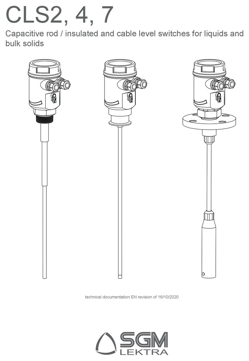
CLS2/4/7
Safety, installation, use and maintenance instructions
Warning: this document is an integral part of the 825B097_ manual and must be read and understood in conjunction with it.
Capacitive level switch European directive: 2014/34/UE
ATEX standard references: EN60079-0:2012+A11:2013; EN60079-11:2012; EN60079-31:2014
Model : CLS_
ATEX Group: II 1/2D
Protection mode: ia/tb
Ambient temperature: -20 ÷ +60°C Protection degree: IP66
Max process temperature: +150°C
Power supply: 24Vdc/ac ÷115Vac; 85 ÷ 250Vac
Output relay SPDT: 5A250Vac
1 - CERTIFIED ATEX VERSION IDENTIFICATION
1. Product code
2. Supply voltagee
2 - SAFETY INSTRUCTIONS
This capacitive level switch is designed to be installed in potentially explosive atmosphere for the combustible dust presence.
Make sure that the device marking is in compliance with the area classication; do not install the device in the explosive gases
presence (0, 1 or 2 zone).
Verify that the probe installation does not aect the degree of protection.
Device improper use may cause damage to people, the product and connected equipments.
Always observe the nameplate data for the power supply and the electrical connections.
3 - INSTALLATION AND COMMISSIONING
The installation must be performed only by qualied and properly trained personnel in accordance with current regulations
(Rif. EN 60079-14). The equipment must be used only after having correctly understood the instructions in this document,
together with the 825B097_ user manual.
The device must be installed so as to avoid the risk of shock to the housing and to the sensitive part.
All the electrical connections must be realized with non-active conductors; be sure that, during wiring operations, the potentially
explosive atmosphere is not present.
Use only the threaded connection (wrench 50) to insert the probe into the process connection; do not use the housing to
manually screw the sensor into the process connection.
Properly tighten the cable glands and the cover, just before commissioning.
When necessary, replace the cable entries with other similar devices, make sure that the marking is in suitable for the
installation area (2D) and the minimum dustproof degree (IP6X).
The housing is provided with a breathing valve: make sure that during the installation, the breathing function is not avoided.
For the electrical connections and instrument settings, please refers to 825B097_ user manual.
SI15002B_EN
1
2
3
4
5
6
20090 Rodano (MI) , Italy
II 1/2D Ex ia/tb IIIC T 150°C
24Vdc/ac - 115Vac
AR 18 ATEX xxx
0051
Type: CLS___ Serial N° ________-20__
Da/Db (Tamb -20 + 60°C)
Via Papa Giovanni XXIII, 49
NON APRIRE SOTTO TENSIONE IN PRESENZA DI
ATMOSFERA ESPLOSIVA
3. Notied body identication code
4. 4. Certicate number
5. 5.Serial Number
6. 6.Marking
Note: the nameplate does not shows intrinsic safety parameters because external connections ARE NOT subjected to
intrinsic safety.
