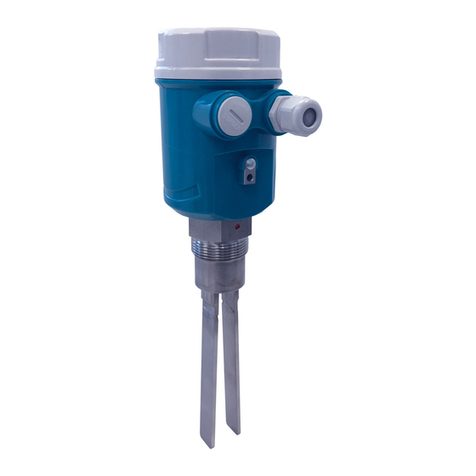
SGM LEKTRA CLS2 Guide

CLS2, 4, 7
Capacitive rod / insulated and cable level switches for liquids and
bulk solids
technical documentation EN revision of 16/10/2020

Page 2 of 16 www.sgm-lektra.com
CLS2, 4, 7 - contents
CONTENTS
1-WARRANTY
2-PRODUCT
3-TECHNICAL SPECIFICATIONS
4-DIMENSIONS
5-INSTALLATION
6-ELECTRICAL CONNECTIONS
7-LOCAL OPERATOR INTERFACE (LOI)-VL601
8-SENSOR CALIBRATION
9-PARAMETER PROGRAMMING
10-TESTING AND QUALITY CERTIFICATE
page 3
page 4
page 5
page 6
page 7
page 10
page 11
page 12
page 13
page 16

Page 3 of 16
www.sgm-lektra.eu
CLS2, 4, 7 - warranty
SGM-LEKTRA SRL undertakes to remedy any fault, defect or absence, occurring within 12 months from the
delivery date, provided that it is attributable to it and has been notified within the prescribed time limit.
SGM LEKTRA SRL may choose whether to repair or replace the faulty products.
The Products replaced under warranty will have an additional 12-month warranty.
The Products repaired under warranty will have a warranty until the original time limit.
The parts of the Products repaired out of warranty will have a 3-month warranty.
The Products are only guaranteed to meet particular specifications, technical characteristics or conditions of use
if this is expressly agreed in the Purchase Agreement or in the documents referred to therein.
The warranty of SGM-LEKTRA SRL absorbs and replaces the warranties and responsibilities, both contractual
and non-contractual, originating from the supply such as, for example, compensation for damages,
reimbursement of expenses, etc., both towards the Customer and towards third parties.
The warranty is void in the event of tampering with or improper use of the Products.
1-WARRANTY

Page 4 of 16 www.sgm-lektra.com
CLS2, 4, 7- product
2-PRODUCT
1. Cover
2. VL601 (opt.)
3. Skintop M20
4. Process connection
5. Covering
6. Rod
7. Anti-condensate filter
2.1 IDENTIFICATION
Every instrument has an adhesive identification plate on which the main information about the meter is outlined.
The following image describes the information and data on the plate.
CLS
24Vdc÷115Vac 85÷230Vac
CC0081604506
2
3
1Mod.
P. S .
S.N.
1. Product code 3. Serial number2. Voltage supply
1
2
3
6
4
5
7

Page 5 of 16
www.sgm-lektra.eu
3-TECHNICAL SPECIFICATIONS
CLS2, 4, 7 - technical specifications
Casing material
PC/AL
Cable/rod material
Carbon steel, AISI316
Insulation/covering material
PVC, PTFE and PE
Mechanical installation and materials
Probe Process connection Materials
CLS2 G 1”, G 1”½ Carbon steel, AISI316
CLS4 G ½”, G 1”, 1” NPT Carbon steel, AISI316
CLS4 G ¾” AISI316
CLS4 G 1”½ Carbon steel, AISI316, PVC, PTFE
CLS4 CLAMP 1”, 1” ½, 2” AISI316
CLS4 COUPLING NUT DN25, DN40, DN50 AISI304L (DIN 11851)
CLS4 FLANGE DN40 PN6 (PVC, PTFE UNI 1092-1), PN16 (Carbon steel, AISI304,
AISI316)
CLS4 FLANGE DN50, DN80, DN100 PN6 (PVC, UNI 1092-1), PN16 (AISI316, DIN 2527 form B )
CLS4 FLANGE ANSI RF2”, RF3”, RF4” AISI316 (150psi)
CLS7 G 1”½ Carbon steel
CLS7 FLANGE DN40 PN16 (Carbon steel, AISI304, AISI316)
CLS7 FLANGE DN50, DN80, DN100 AISI316 (DIN 2527 form B)
CLS7 FLANGE ANSI RF2”, RF3”, RF4” AISI316 (150psi)
Protection rating
IP67/IP68 in process
Pressure
-1 ÷ +6bar
Operating temperature
-20÷+60°C (-40÷150°C vers. PTFE with heat sink)
Power supply
24Vdc ÷ 115V 85÷230Vac
Max. input power
1,5W
Cable glands
M20x1,5
Electrical connection
Plug-in terminal blocks
Relay output
3A 230Vac
Trigger mode
min. or max. level
Trigger delay
0÷30s (programmable)
Programming
Via extractable VL601 module
Void calibration
for self-acquisition through extractable VL601-SGM module
Thermal stability
1 typical minute
Display
LCD display on extractable VL601-SGM module
Greed LED: power on
Red LED: relay status (on with relay energized)
Certification
ATEX II 1/2D Ex ia/tb IIIC T150°C (opt.)

Page 6 of 16 www.sgm-lektra.com
4-DIMENSIONS
CLS2, 4, 7 - dimensions
5.1 MECHANICAL DIMENSIONS
Ø95 130
132,5
250
1"½ G

Page 7 of 16
www.sgm-lektra.eu
CLS2, 4, 7 - installation
5-INSTALLATION
5.1 PRECAUTIONS FOR INSTALLATION
5.1.1 CORRECT INSTALLATION
Correct installation of CLS sensors to control a Max. level (a) and Min. level (b). To avoid triggering problems,
follow the instructions below:
- Install away from loading zones and keep a minimum distance of 300mm from the walls of the tank.
- When placing the order, select the option for the cable extension length, allowing the sensitive element
to be positioned at least 200 mm from the bottom of the tank.
- Pay particular attention to the maximum load for minimum level CLS sensors (b).
The mechanical load during discharge must not exceed a value of:
3000N for process temperatures below 40°C
2800N for process temperatures with a max. value of 70°C (80° non-continuous)
- Position the CLS2 sidewise at 30° angle (minimum), preferably with a sun protector plate (c)
Min. dist.
300mm
Min. dist.
200mm
“a” “b”
Maximum
level
Minimum
level
Max. load
3000N
“c”

Page 8 of 16 www.sgm-lektra.com
CLS2, 4, 7 - installation
5.1.2 Incorrect installation
• Incorrect installation of CLS sensors.
• do not install near loading zones (d); false alarm signals may be generated and the CLS sensors may be
damaged by the pouring in of the material.
• do not install at the centre of the tank loading point (e); the CLS sensors and/or ceiling of the tank may be
damaged and eventually break the cable of the CLS sensors, due to the elevated mechanical stress created
in this point.
• do not install in points where accumulations of product may form (f); the CLS sensors might remain blocked in
the ‘product present’ position: false max. level alarm or, vice versa, failed min. level alarm signal.
• the CLS2 probes with rope extension cannot be installed sidewise (g).
“d” “e” “f”
“g”

Page 9 of 16
www.sgm-lektra.eu
CLS2, 4, 7 - installation
5.1.3 Cable
Bent cable (h-i)
The cable must be straightened (l) to prevent the sensitive element from touching the wall of the tank and sending
a false ‘product present’ signal: false max. level alarm or, vice versa, failed min. level alarm signal.
“h” “i” “l”

Page 10 of 16 www.sgm-lektra.com
CLS2, 4, 7 - electrical connection
6-ELECTRICAL CONNECTION
6.1 CONNECTIONS
1) Before energizing this product, make sure all connections have been correctly made and that the mains
voltage corresponds to that on the rating plate.
2) Tighten the cable glands and cover to ensure a protection rating of IP67.
3) To prevent the infiltration of water or humidity, which may damage the level sensor, do not remove the caps
of unused cable glands.
6.2 INFILTRATIONS OF HUMIDITY
To avoid infiltrations of humidity inside the cover, we recommend:
- Using a cable with an external diameter of 6÷12mm for the electrical connections and fully tightening the M20
cable gland
- Fully tighten the cover
- Position the cable in such a way as to form a downward curve in the output of the M20 cable gland;
in this way condensation and/or rainwater will tend to drip from the bottom of the curve.
NO
C
NC
+Vdc / L (Vac)
-Vdc / N (Vac)
24Vdc÷115Vac and
85÷230Vac RL
Plug-in terminal blocks for connection of
power supply
Power ON green LED: On and fixed
Plug-in terminal blocks for connection of
relay contacts
RL red LED indicates the status of the relay:
on, RL relay energized
Earth connection of connector

Page 11 of 16
www.sgm-lektra.eu
CLS2, 4, 7 - local operator interface (LOI) - VL601
7-LOCAL OPERATOR INTERFACE (LOI) - VL601
The CLS capacitive level checks are programmed and calibrated using the VL601 display module
7.1 VL601 FEATURES
The VL601 programming module can be activated and deactivated on-board the CLS without affecting the unit’s
operation.
The VL601 module is equipped with an LCD dot-matrix display and allows simple and fast start-up using the 4
programming keys.
The symbol ON on the display indicates that the relay is energized, normal condition.
The symbol OFF on the display indicates that the relay is de-energized, alarm condition.
1. From “RUN” mode: press to select the parameter to be programmed.
2. Press to confirm the selection.
3. To select the parameter option press .
4. Press to confirm and save the selection, press to exit without saving.
LEFT-HAND ARROW key:
• Exit without saving
• When pressed with the ENTER
key performs a void calibration
UP ARROW key:
• Parameter option selection
SCROLL key:
• Scroll parameters
ENTER key:
• Confirm parameter selection
• Save parameter setting
By unscrewing the cover, it is possible to lock the VL601 module (by turning it clockwise until it clicks) or unlock it
(by turning it anti-clockwise) as shown in the figure.
LOCK UNLOCK

Page 12 of 16 www.sgm-lektra.com
CLS2, 4, 7 - sensor calibration
8-SENSOR CALIBRATION
From “RUN” mode, press ENTER and the LEFT-HAND ARROW at the same
time
During the calibration of the sensor, the VL601 module display will show the
wording “VOID. COMPENSATION”.
Once the sensor calibration data has been correctly acquired, the VL601
module display will show the wording “- OK -”
When sensor calibration is complete, the system will automatically return to
“RUN” mode
VOID. COMPENSATION
TH: 0300
SENS: NORM
DELAY: 00 S
MODE: MAX
Ź
ON
127
CAUTION: In order to correctly calibrate the sensor, ensure the real level is in the ‘sensor unoccupied’ condition.
- OK -
TH: 0300
SENS: NORM
DELAY: 00 S
MODE: MAX
Ź
ON
127

Page 13 of 16
www.sgm-lektra.eu
CLS2, 4, 7 - parameter programming
9-PARAMETER PROGRAMMING
9.1 TH
Press ENTER to modify the programming. Using the UP ARROW adjust the
limit from 0 to 1000:
during programming a “transparent” cursor will be displayed
which indicates the new positioning of the level alarm limit.
Press ENTER to confirm.
NOTE: the TH value must always be greater than the value shown in void
conditions.
TH: 0300
SENS: NORM
DELAY: 00 S
MODE: MAX
Ź
ON
127
9.2 SENS
Press ENTER to modify the programming.
Set the sensor sensitivity: NORMAL or HIGH.
The table shows a few examples of how the “SENS” parameter should be
set in relation to the material.
TH: 0300
SENS: NORM
DELAY: 00 S
MODE: MAX
Ź
ON
HIGH (high sens.) NORM (normal sens.)
Sunflower seeds Cornflour
Plast. chips in ABS Wheat flour
Plast. chips in PA Rice
Bran Cement
9.2 DELAY
Press ENTER to modify the programming.
Using the UP ARROW, adjust the delay time from 0 to 30 seconds for the
switching of the sensor from the normal state to the alarm state
(for MAX alarm, relay de-energized in the absence of product; for MIN alarm,
relay de-energized in the absence of product).
When the process ceases to be in alarm conditions, the sensor instantly
switches without a delay, from the alarm state to the normal state
(for MAX alarm, relay energized in absence of product;
for MIN alarm, relay energized in presence of product).
TH: 0300
SENS: NORM
DELAY: 00 S
MODE: MAX
ŹON
9.3 MODE
Press ENTER to modify the programming. Set the sensor alarm mode.
Use the UP ARROW to change the alarm mode, MAX or MIN,
highlighted in negative.
Press ENTER to confirm.
TH: 0300
SENS: NORM
DELAY: 00 S
MODE: MAX
Ź
ON

Page 14 of 16 www.sgm-lektra.com
CLS2, 4, 7 - parameter programming
By setting the MODE parameter with the “MAX” option, the CLS sensors will work in maximum level alarm mode:
- normal condition; relay energized in absence of product
- alarm condition; relay de-energized in presence of product
NO
C
NC
Led RL
ON
RL
NORMAL
CONDITION
TH: 0300
SENS: NORM
DELAY: 00 S
MODE: MAX
Ź
ON
NO
C
NC
Led RL
OFF
RL
TH: 0300
SENS: NORM
DELAY: 00 S
MODE: MAX
Ź
OFF
ALARM
CONDITION
By setting the MODE parameter with the “MIN” option, the CLS sensor will work in minimum level alarm mode:
- normal condition; relay energized in presence of product
- alarm condition; relay de-energized in absence of product
NO
C
NC
Led RL
ON
RL
TH: 0300
SENS: NORM
DELAY: 00 S
MODE: MAX
Ź
ON
NORMAL
CONDITION
NO
C
NC
Led RL
OFF
RL
TH: 0300
SENS: NORM
DELAY: 00 S
MODE: MAX
Ź
OFF
ALARM
CONDITION

Page 15 of 16
www.sgm-lektra.eu

SGM-LEKTRA S.r.l.
Via Papa Giovanni XXIII, 49
20090 Rodano (MI) - ITALY
tel: ++39 02 95328257
fax: ++39 02 95328321
e-mail: [email protected]
web: sgm-lektra.com
Documentation subject to technical change with no prior warning
10-FACTORY TEST AND QUALITY CERTIFICATE
In conformity to the company and check procedures I certify that the equipment:
is conform to the technical requirements on Technical Data and it is made in conformity to the procedure
Quality Control Manager: .......................................................... Production and check date: .................................................
(Electronic Unit) (Capacitive probe)
Other manuals for CLS2
1
This manual suits for next models
2
Table of contents
Other SGM LEKTRA Switch manuals
Popular Switch manuals by other brands

Cisco
Cisco SRW248G4 - Small Business Managed Switch datasheet
TRENDnet
TRENDnet TU2-700 - DATA SHEETS Quick installation guide
Alcatel-Lucent
Alcatel-Lucent 7210 SAS E OS user manual
HP
HP aruba 6300M Installation, Safety, and Regulatory Information
IOGear
IOGear GCS602 user manual
Gefen
Gefen EXT-DPKVM-422 user manual
