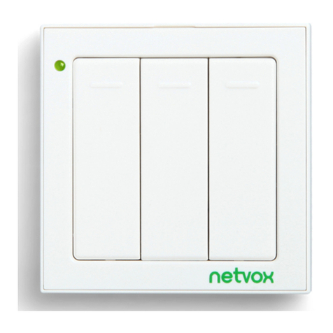
netvox EmberLux BLZ-US-01 User manual

US EmberLux Switch
User Manual
EmberLux Switch
Model: BLZ-US-01
Firmware: V0.6 and below
Hardware: V1.0 and below
20150923
FW V0.1~V0.5

1
Table of Contents
1. Introduction.............................................................................................................................................................. 2
2. Product Appearance.................................................................................................................................................3
3. Specification.............................................................................................................................................................. 4
4. Installation.................................................................................................................................................................4
5. Setting up ...................................................................................................................................................... 4
5-1. Join the ZigBee Network................................................................................................................................ 4
5-2. Control.............................................................................................................................................................4
5-3. Sleeping Mode................................................................................................................................................ 5
5-4. Turn On ...............................................................................................................................................5
5-5. Battery............................................................................................................................................................. 6
5-6. Restore to Factory Setting...............................................................................................................................6
6. Home Automation Clusters for .................................................................................................................. 6
7. Netvox App control.................................................................................................................................................. 9
8. ZiG-BUTLER......................................................................................................................................................... 11
8-1. Join into the network........................................................................................................................ 11
8-2. Bind ...................................................................................................................................................11
8-3. Power Consumption Report..........................................................................................................................13
9. Related Netvox Devices..........................................................................................................................................17
10. Important Maintenance Instructions................................................................................................................. 17
BLZ-US-01
BLZ-US-01
BLZ-US-01
BLZ-US-01
BLZ-US-01

2
1. Introduction
Netvox , a battery-powered wall switch, acts as an End Device in ZigBee network. It does not perform
permit-join function as a coordinator or a router for other devices to join the network. is featured to control
the On/Off device or the dimmable device.
What is ZigBee?
ZigBee is a short range wireless transmission technology based on IEEE802.15.4 standard and supports multiple
network topologies such as point-to-point, point-to-multipoint, and mesh networks. It is defined for a
general-purpose, cost-effective, low-power-consumption, low-data-rate, and easy-to-install wireless solution for
industrial control, embedded sensing, medical data collection, smoke and intruder warning, building automation
and home automation, etc.
BLZ-US-01 BLZ-US-01

3
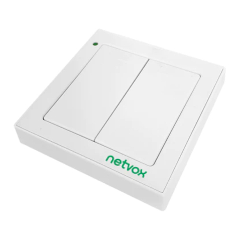
2. Product Appearance
LED Indicator
Button 2 (Off)
Button 1 (On)
Reset Key
Battery Holder

4
3. Specification
Fully IEEE 802.15.4 compliant
Utilizes 2.4GHz ISM band; up to 16 channels
Power supply: 2 x AAA batteries
Up to 70 meters wireless transmission range in non-obstacle space
Easy installation and configuration
Operation temperature: -10 ℃~ 50 ℃
4. Installation
This device is NOT truly waterproof/ resistant and is for indoor use.
5. Setting up
5-1. Join the ZigBee Network
After is powered on or turned on, it will search for an existing ZigBee network and send a request to
join the network automatically. While is under the coverage from a coordinator or a router whose
permit-join feature is enabled, will be permitted to join the network.
(1) Enable the permit-join function (valid for 60 seconds) of a coordinator or a router (please refer to the user
manual of the coordinator or the router to enable the permit-join feature).
(2) Power on or turn on . It will start to search and join the network.
(3) will search the network every 3 seconds and attempts the searching for 60 times. Each searching
will go with a magenta flash.
(4) After 60 attempts, will go into the sleeping mode. Please try step1~2 to start
the searching again.
(5) The indicator will flash cyan for 5 minutes after it is joined successfully.
(6) If the magenta flash stops and network indicator had no responds, it shows join fails. Please repeat (1)-(3).
5-2. Control
can bind with on/off device and dimming device. Bind device can accept on/off or dimming
BLZ-US-01
BLZ-US-01
BLZ-US-01
BLZ-US-01
BLZ-US-01
BLZ-US-01
BLZ-US-01
BLZ-US-01

5
command from Z970A. For example, after binds with Z809B successfully, press control
button of the bind device Z809B will receive command and act correspondingly (including
normal bind and group bind).
A. On/Off control (0x0006)
(1) Short press Button 1 (network indicator flash once for 0.5s)→ send the turn-on command.
(2) Short press Button 2 (network indicator flash once for 0.5s)→ send the turn-off command.
B. Level/Dimming Control (0x0008)
(1) Press and hold Button 1 over 1 second (network indicator flashes once for 0.5s)
→ send Step With On command→dimming up.
(2) Press and hold Button 2 over 2 second (network indicator flashes once for 0.5s)
→ send the Step With Off command→dimming down.
(3) Release Button → send the stop command (network indicator flashes once for 0.5s)
→dimming stops.
5-3. Sleeping Mode
is designed to go into sleeping mode for power-saving in some situations:
(1) While the device is in the network → the sleeping period is 5 minutes; it will wake up every 5 minutes to
keep online.
(2) When it doesn’t find a network to join → will go to sleeping mode. It will wake up every 15
minutes to search a network to join.
(3) Once was joined to a network and by any chance the network is no longer existed or the device is
out of the network → will wake up every 15 minutes to find the network it joined before and flash
magenta once (on 500ms, off 500ms).
Status (3) would consume up to 30 times power spending compared to (1) & (2). To prevent this
unwanted power consumption, we recommend that users remove the batteries to power off the device.
5-4. Turn On
For power saving, is designed to get into sleeping mode when there is no activity for 2 minutes.
To manually turn on , press the Reset Key once.
When is first time used or after resetting → it will try to join the network.
When is in a ZigBee network → it will send out the device data, like IEEE address/Network
address, and will be activated for 2 minutes.
When was in a ZigBee network, but by any change it is offline → it will start to rejoin the
ZigBee network.
BLZ-US-01
BLZ-US-01
BLZ-US-01
BLZ-US-01
BLZ-US-01
BLZ-US-01
BLZ-US-01
BLZ-US-01
BLZ-US-01
BLZ-US-01
BLZ-US-01
BLZ-US-01

6
5-5. Battery
When the operating voltage is lower than 2.4V, will send a low-power report to the ZigBee network.
5-6. Restore to Factory Setting
To restore it to factory setting, please follow the steps:
Step1. Remove the batteries to power off .
Step2. Press and hold the Reset Key, then power on to complete the restore.
6. Home Automation Clusters for
A cluster is a set of related attributes and commands which are grouped together to provide a specific function. A
simple example of a cluster would be the On/Off cluster which defines how an on/off switch behaves. This table
lists the clusters which are supported by .
1.End Point(s): :0x01
2.Device ID:Dimmer Switch (0x0104)
3.EndPoint Cluster ID
Attributes of the Basic Cluster Information
Identifier Name Type Range Access Default Mandatory /
Optional
0x0000 ZCLVersion Unsigned
8-bit integer
0x00 –
0xff
Read only 03 M
Server side Client side
Basic (0x0000)
Power Configuration(0x0001)
Identify (0x0003)
On/off switch configuration(0x0007) On/off(0x0006)
Commissioning(0x0015)Level control(0x0008)
Poll Control(0x0020)
Diagnostics(0x0B05)
BLZ-US-01
BLZ-US-01 BLZ-US-01
BLZ-US-01
BLZ-US-01
BLZ-US-01

7
0x0001 ApplicationVersion Unsigned
8-bit integer
0x00 –
0xff
Read only 03 O
0x0002 StackVersion Unsigned
8-bit integer
0x00 –
0xff
Read only 53 O
0x0003 HWVersion Unsigned
8-bit integer
0x00 –
0xff
Read only 01 O
0x0004 ManufacturerName Character
string
0 – 32
bytes
Read only netvox O
0x0005 ModelIdentifier Character
string
0 – 32
bytes
Read only Z970BE3ED O
0x0006 DateCode Character
string
0 – 16
bytes
Read only - O
0x0007 PowerSource 8-bit
Enumeration
0x00 –
0xff
Read only 0x03 M
0x0010 LocationDescription Character
string
0 – 16
bytes
Read/write - O
0x0011 PhysicalEnvironmen
t
8-bit
Enumeration
0x00 –
0xff
Read/write 0x00 O
0x0012 DeviceEnabled Boolean 0x00 –
0x01
Read/write 0x01 O
Attributes of the Power Configuration Information
Identifier Name Type Range Access Default Mandatory
/ Optional
0x0020 Battery voltage Unsigned
8-bit integer
0x00 –
0xff
Read /
write
O
0x0031 BatterySize 8-bit
Enumeration
0x00 –0
xff
Read /
write 4 O
0x0033 BatteryQuantity Unsigned 0x00 – Read / 2 O

8
On/Off configuration cluster
Identifier Name Type Range Access Default Mandatory
/ Optional
0x0000
SwitchType
8-bit
Enumeration 0x00 –0x01 Read
only 0x00 M
0x0010 SwitchAction
s
8-bit
Enumeration
0x00 –0x02 Read 0x02 M
8-bit integer 0xff write
0x0035 BatteryAlarmMask Bitmap
(8-bits)
0000
000x
Read /
write 0000 0001 O
0x0036 BatteryVoltageMinT
hreshold
Unsigned
8-bit integer
0x00 –
0xff
Read /
write 24 O
0x0037 BatteryVoltageThres
hold1
Unsigned
8-bit integer
0x00 –
0xff
Read /
write 25 O
0x0038 BatteryVoltageThres
hold2
Unsigned
8-bit integer
0x00 –
0xff
Read /
write 26 O
0x0039 BatteryVoltageThres
hold3
Unsigned
8-bit integer
0x00 –
0xff
Read /
write 27 O
0x003e BatteryAlarmState
32-bit
Bitmap
0x00…
x
Read
0x000…
0
O

9
7. Netvox App control
1. Add device to Netvox system, the added device list will show up in device management as below,
2、Click “Setting” into device interface as below:
Click “Pairing configuration” into binding interface. Click “Pair Devices ” (ex. LED dimmable light). Click
“bind” on the right-top.(Note: before binding, users need to turn on ED for fear that ED is in sleeping mode which
may cause binding fails.) When the binding is completed, App interface will show as below:

10
After binding, is able to control dimming switch to turn on/off and adjust brightness. If users want to
unbind device, long press bind device item, message “unbind” will show up as below on the left as below. (Note:
before clicking “unbind”, users need to turn on ED.) After unbinding completely, item will disappear.
BLZ-US-01

11
8. ZiG-BUTLER
8-1. Join into the network
When ZiG-BUTLER sees a coordinator or a router device, it will show the icon.
Right click on the icon of the coordinator or the router and choose Set Permit Join On.
After has successfully joined, the icon will be appeared in ZiG-BUTLER.
8-2. Bind
(1) Right click on the End Point of and select Bind.
BLZ-US-01
BLZ-US-01
BLZ-US-01
BLZ-US-01
BLZ-US-01

12
(2) On the Device tab, select the device to which you would like to bind. Next, click Select ClusterID, choose
the Cluster, and click OK.
The information would be pop-up after the binding is completed.
Note: to bind the device via Zig-butler, please make sure is on. We suggest to turn on
before binding.
(3) Right click on the End Point of and select Properties to view the binding information.
BLZ-US-01
BLZ-US-01 BLZ-US-01

13
8-3. Power Consumption Report
(1) Right click on the End Point of and select Properties to overview the power consumption.
(2) In binding list, we can see bind request information of other devices. If bind device and
share the same cluster ID: 0001 of binding request. Then will report data to the bind device.
Below figures shows alarming range of voltage. The default minimum alarming voltage is 2.4V.
(3) is able to send data to relate bind device via “Config Report” process.
Right click on the End Point of and select Bind.
BLZ-US-01
BLZ-US-01
BLZ-US-01
BLZ-US-01
BLZ-US-01

14
(4) On the Device tab, select the device to which you would like to bind. Next, click Select ClusterID, choose
the Cluster, and click OK.
Choose bind device sharing the same cluster ID: 0001 of binding request through “device’.
to choose cluster ID which is needed.
(5) Right click on the End Point of and select Properties.
(6) On the Report Config tab, check Auto to modify the settings. Click Set to complete the setting.
If there is no customized setting, the default 0X0020 shows as below:
(a) 0X0020 default Min. 3600 seconds. Max. 3600 seconds. Reportable change = 0.
(b) 0X0035 default battery alarm mask = 1.
(c) 0X0036 default battery voltage min threshold=2.4V
BLZ-US-01

15
(7) Click set to customize:
Min: the minimum reporting internal (second)
Max: the maximum reporting internal (second)
Reportable change: reports data instantly when the change rate is more than this value.
BLZ-US-01

16
Report setting interval table:
Min Interval
(Unit:second)
Max Interval
(Unit:second)
Reportable
Change
Change rate≥ Reportable
Change
Change rate<
Reportable Change
1-65534 1-65534
≠0To report per Minimum
interval
To report per Maximum
interval
0To report per Minimum
interval
To report per Minimum
interval
0 1-65534
≠0 To report instantly To report per Maximum
interval
0 To report per second To report per second
1-65534 0
≠0To report per Minimum
interval No report
0To report per Minimum
interval
To report per Minimum
interval
0 0
≠0 To report instantly No report
0 To report per second To report per second
Any 65535 Any Stop reporting
65535 Any Any Stop reporting
Note:(1)It is not suggested to set:
Min Interval =0,
Reportable Change=0,
Z809A will report very densely to block up the network.
(2)Yellow areas are not suggested.
(3) Reportable change unit: V.
(4) Once binding completes, will send data report to bind device. Default min. and max. is
3600 seconds. While detects low voltage, it will send warning.
(5) Low voltage waning mode 0X003E and voltage ID 0X0020 share the same cluster 0x0001.
Once binding with cluster 0x0001, there is no need to bind 0X003E and 0X0020 again.
BLZ-US-01
BLZ-US-01

17
9. Related Netvox Devices
Z806: Output Unit
ZC06: Dimmable LED Tube
10. Important Maintenance Instructions
Please keep the device in a dry place. Precipitation, humidity, and all types of liquids or moisture can contain
minerals that corrode electronic circuits. In cases of accidental liquid spills to a device, please leave the device
dry properly before storing or using.
Do not use or store the device in dusty or dirty areas.
Do not use or store the device in extremely hot temperatures. High temperatures may damage the device or
battery.
Do not use or store the device in extremely cold temperatures. When the device warms to its normal
temperature, moisture can form inside the device and damage the device or battery.
Do not drop, knock, or shake the device. Rough handling would break it.
Do not use strong chemicals or washing to clean the device.
Do not paint the device. Paint would cause improper operation.
Handle your device, battery, and accessories with care. The suggestions above help you keep your device
operational. For damaged device, please contact the authorized service center in your area.

18
FCC Statement:
This device complies with part 15 of the FCC Rules. Operation is subject to the following
two conditions: (1) This device may not cause harmful interference, and (2) this device
must accept any interference received, including interference that may cause undesired
operation.
This equipment has been tested and found to comply with the limits for a Class B digital
device, pursuant to part 15 of the FCC Rules. These limits are designed to provide
reasonable protection against harmful interference in a residential installation. This
equipment generates, uses and can radiate radio frequency energy and, if not installed
and used in accordance with the instructions, may cause harmful interference to radio
communications. However, there is no guarantee that interference will not occur in a
particular installation. If this equipment does cause harmful interference to radio or
television reception, which can be determined by turning the equipment off and on, the
user is encouraged to try to correct the interference by one or more of the following
measures:
—Reorient or relocate the receiving antenna.
—Increase the separation between the equipment and receiver.
—Connect the equipment into an outlet on a circuit different from that to which the
receiver is connected.
—Consult the dealer or an experienced radio/TV technician for help.
Caution: Any changes or modifications not expressly approved by the party responsible
for compliance could void the user's authority to operate the equipment.
Table of contents
Other netvox Switch manuals
Popular Switch manuals by other brands
Mellanox Technologies
Mellanox Technologies SX1710 Quick installation guide
Eaton
Eaton T6-160-6 /HI11 Series Instruction leaflet

Allied Telesis
Allied Telesis AT-8012M installation guide
PureTools
PureTools PT-HDBT-220WP user manual
Linkskey
Linkskey LDV-002ESK Quick installation guide
Lindy
Lindy 3 Port user manual
