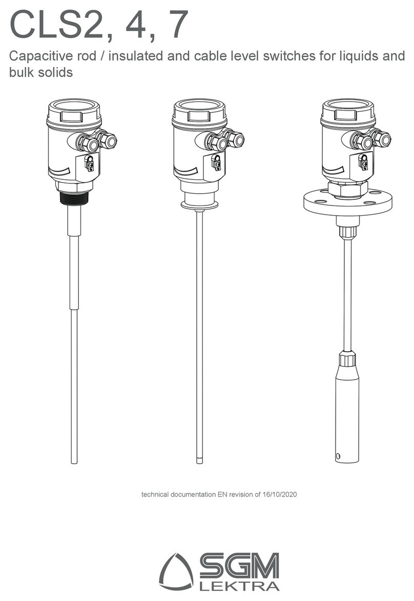
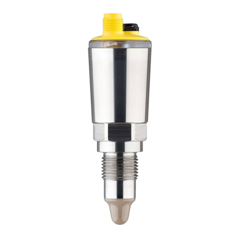
SGM LEKTRA RSL200 User manual

RSL200
vibration level switch, with rigid and semi-flexible extension for bulk
solids and powders.
technical documentation EN Rev. M

Page 2 of 16 www.sgm-lektra.com
RSL200 - contents
CONTENTS
1-WARRANTY
2-PRODUCT
3-TECHNICAL SPECIFICATIONS
4-DIMENSIONS
5-INSTALLATION
6-ELECTRICAL CONNECTIONS
7-LOCAL OPERATOR INTERFACE (LOI)-VL601
8-PARAMETER PROGRAMMING
9-TESTING AND QUALITY CERTIFICATE
page 3
page 4
page 5
page 6
page 7
page 10
page 11
page 12
page 16

Page 3 of 16
www.sgm-lektra.eu
RSL200 - warranty
Products supplied by SGM LEKTRA are guaranteed for a period of 12 (twelve) months from delivery date according to
the conditions specified in our sale conditions document.
SGM LEKTRA can choose to repair or replace the Product.
If the Product is repaired it will maintain the original warranty terms, whereas if the Product is replaced it will have 12
(twelve) months of warranty.
The warranty will be null if the Client modifies, repair or uses the Products for other purposes than the normal conditions
foreseen by instructions or Contract.
In no circumstances shall SGM LEKTRA be liable for direct, indirect or consequential or other loss or damage whether
caused by negligence on the part of the company or its employees or otherwise howsoever arising out of defective goods
1-WARRANTY

Page 4 of 16 www.sgm-lektra.com
RSL200- product
2- 2- PRODUCT
1. Cover
2. VL601 (opt.)
3. Skintop M20
4. Process connection
5. Forks
6. Anti-condensate filter
2.1 IDENTIFICATION
Every instrument has an adhesive identification plate on which the main information about the meter is outlined.
The following image describes the information and data on the plate.
RSL200A0F1D
CV0081901422
2
3
1Mod.
P.S.
S.N.
85÷250Vac
1. Product code 3. Serial number2. Power supply
1
2
3
5
4
6

Page 5 of 16
www.sgm-lektra.eu
3-3- TECHNICAL SPECIFICATIONS
RSL200 - technical specifications
Casing material
PC/AL
Vibrating prong material
AISI316 (AISI304 for semi-flexible extension tube)
Protection rating
IP67/IP68 in process
Pressure
-1 ÷ +6bar
Ambient temperature
-20 to +60°C
Max. process temperature
150°C
Power supply
24Vdc ÷ 115Vac; 85÷230Vac
Max. input power
1.5W
Cable glands
M20x1.5
Electrical connection
Plug-in terminal blocks
Relay output
3A 230Vac
Trigger mode
min. or max. level
Trigger delay
0÷30s (programmable)
Programming
Via extractable VL601 module
Trigger sensitivity and delay
configurable via VL601
Thermal stability
1 typical minute
Display
LCD display on extractable VL601-SGM module Green LED: power on
Red LED: relay status (on with relay energized)
Certification
ATEX II 1/2D Ex ta/tb IIIC T150°C Da/Db (opt.)

Page 6 of 16 www.sgm-lektra.com
4-4- DIMENSIONS
RSL200 - dimensions
5.1 MECHANICAL DIMENSIONS
Ø95 130
132,5
1"½ G
155
20
353
Ø95
132,5
1"½ G
130
20
513
Ø95
132,5
1"½ G
20
Ø12
86 62155
45,5
20
155 205,5
20
130
20
L=....
L=....

Page 7 of 16
www.sgm-lektra.eu
RSL200 - installation
5-5- INSTALLATION
5.1 PRECAUTIONS FOR INSTALLATION
5.1.1 CORRECT INSTALLATION
Correct installation of RSL200 sensors to control a Max. level (“a” and “c”) and Min. level (b).
To avoid triggering problems, follow the instructions below:
- Install away from loading zones and keep a minimum distance of 300mm from the walls of the tank.
- When placing the order, select the option for the extension length, allowing the sensitive element to be
positioned at least 200 mm from the bottom of the tank.
Min. dist.
300mm
Min. dist.
200mm
“a” “b”
“c”
Maximum
level
Minimum
level

Page 8 of 16 www.sgm-lektra.com
RSL200 - installation
5.1.2 Incorrect installation
Incorrect installation of RSL200 sensors.
• do not install near loading zones (c); false alarm signals may be generated and the RSL200 sensors may be
damaged by the pouring in of the material.
• do not install at the centre of the tank loading point (d); the RSL200 sensors and/or ceiling of the tank may be
damaged and eventually break the RSL200 sensor, due to the elevated mechanical stress created in this point.
• do not install in points where accumulations of product may form (e); the RSL200 sensors might remain blocked
in the ‘product present’ position: false max. level alarm or, vice versa, failed min. level alarm signal.
“c” “d” “e”

Page 9 of 16
www.sgm-lektra.eu
RSL200 - installation
5.1.3 Semiflex Extension
Bent extension (h) (g)
The extension must be straightened (i) to prevent the sensitive element from touching the wall of the tank and
sending a false ‘product present’ signal: false max. level alarm or, vice versa, failed min. level alarm signal.
“g” “h” “i”

Page 10 of 16 www.sgm-lektra.com
RSL200 - electrical connections
NO
C
NC
+Vdc / L (Vac)
-Vdc / N (Vac)
24Vdc÷115Vac and
85÷230Vac RL
Plug-in terminal blocks for connection of
power supply
Power ON green LED: On and fixed
Plug-in terminal blocks for connection of
relay contacts
RL red LED indicates the status of the relay:
on, RL relay energized
Earth connection of connector
6-ELECTRICAL CONNECTION
6.1 CONNECTIONS
1) Before energizing this product, make sure all connections have been correctly made and that the mains voltage
corresponds to that on the rating plate.
2) Tighten the cable glands and cover to ensure a protection rating of IP67.
3) To prevent the infiltration of water or humidity, which may damage the level sensor, do not remove the caps
of unused cable glands.
6.2 INFILTRATIONS OF HUMIDITY
To avoid infiltrations of humidity inside the cover, we recommend:
- Using a cable with an external diameter of 6÷12mm for the electrical connections and fully tightening the M20
cable gland
- Fully tighten the cover
- Position the cable in such a way as to form a downward curve in the output of the M20 cable gland;
in this way condensation and/or rainwater will tend to drip from the bottom of the curve.

Page 11 of 16
www.sgm-lektra.eu
RSL200 - local operator interface (LOI) - VL601
7-LOCAL OPERATOR INTERFACE (LOI) - VL601
The RSL200 vibration level checks are programmed and calibrated using the VL601 display module
7.1 VL601 FEATURES
The VL601 programming module can be activated and deactivated on-board the RSL200 without affecting the
unit’s operation.
The VL601 module is equipped with an LCD dot-matrix display and allows simple and fast start-up using the 4
programming keys.
The symbol
ON
on the display indicates that the relay is energized, normal condition.
The symbol
OFF
on the display indicates that the relay is de-energized, alarm condition.
1. From “RUN” mode: press to select the parameter to be programmed.
2. Press to confirm the selection.
3. To select the parameter option press .
4. Press to confirm and save the selection, press to exit without saving.
LEFT-HAND ARROW key:
• Exit without saving
• When pressed with the ENTER key
performs a void calibration
UP ARROW key:
• Parameter option selection
SCROLL key:
• Scroll parameters
ENTER key:
• Confirm parameter selection
• Save parameter setting
By unscrewing the cover, it is possible to lock the VL601 module (by turning it clockwise until it clicks) or unlock it
(by turning it anti-clockwise) as shown in the figure.
LOCK UNLOCK

Page 12 of 16 www.sgm-lektra.com
RSL200 - parameter programming
8-PARAMETER PROGRAMMING
8.1 TH
Press ENTER to modify the programming.
Using the UP ARROW adjust the limit from 0 to 1000:
during programming a “transparent” cursor will be displayed, which indicates
the new positioning of the level alarm limit. Press ENTER to confirm.
NOTE: the TH value must always be less than the value shown in void conditions.
TH: 0350
DELAY: 00 S
MODE: MAX
ŹON
850
In the case of “light” products that tend not to completely block the vibrating forks,
it may be necessary to set the TH value close to the free vibration value.
TH: 0700
DELAY: 00 S
MODE: MAX
ŹON
850
8.2 DELAY
Press ENTER to modify the programming.
Using the UP ARROW, adjust the delay time from 0 to 30 seconds for the
switching of the sensor from the normal state to the alarm state
(for MAX alarm, relay de-energized in the presence of product;
for MIN alarm, relay de-energized in the absence of product).
When the process ceases to be in alarm conditions, the sensor
instantly switches without a delay, from the alarm state to the normal state
(for MAX alarm, relay energized in absence of product; for MIN alarm, relay
energized in presence of product).
TH: 0350
DELAY: 00 S
MODE: MAX
ŹON
8.3 MODE
Press ENTER to modify the programming. Set the sensor alarm mode.
Use the UP ARROW to change the alarm mode, MAX or MIN,
highlighted in negative.
Press ENTER to confirm.
TH: 0350
DELAY: 00 S
MODE: MAX
ŹON

Page 13 of 16
www.sgm-lektra.eu
RSL200 - parameter programming
By setting the MODE parameter with the “MAX” option, the RSL200 sensors will work in maximum level alarm mode:
- normal condition; relay energized in absence of product
- alarm condition; relay de-energized in presence of product
NO
C
NC
Led RL
ON RL
NORMAL
CONDITION
TH: 0300
DELAY: 00 S
MODE: MAX
ŹON
NO
C
NC
Led RL
OFF
RL
ALARM
CONDITION
TH: 0300
DELAY: 00 S
MODE: MAX
ŹOFF
By setting the MODE parameter with the “MIN” option, the RSL200 sensor will work in minimum level alarm mode:
- normal condition; relay energized in presence of product
- alarm condition; relay de-energized in absence of product
NO
C
NC
Led RL
ON RL
TH: 0300
DELAY: 00 S
MODE: MIN
ŹON
NORMAL
CONDITION
NO
C
NC
Led RL
OFF
RL
TH: 0300
DELAY: 00 S
MODE: MIN
ŹOFF
ALARM
CONDITION

Page 14 of 16 www.sgm-lektra.com
RSL200 - notes
NOTES
________________________________________________________________________________________________________
_______________________________________________________________________________________
_______________________________________________________________________________________
_______________________________________________________________________________________
_______________________________________________________________________________________
_______________________________________________________________________________________
_______________________________________________________________________________________
_______________________________________________________________________________________
____________________________________________________________________ ______________________
____________________________________________________________________________________________________
________________________________________________________________________________________
________________________________________________________________________________________
________________________________________________________________________________________
________________________________________________________________________________________
________________________________________________________________________________________
________________________________________________________________________________________
________________________________________________________________________________________
___________________________________________ _____________________________________________________
________________________________________________________________________________________________
________________________________________________________________________________________
________________________________________________________________________________________
________________________________________________________________________________________
________________________________________________________________________________________
________________________________________________________________________________________
________________________________________________________________________________________
________________________________________________________________________________________
________________ _____________________________________________________________________________________
__________________________________________________________________________________________
________________________________________________________________________________________
________________________________________________________________________________________
________________________________________________________________________________________
________________________________________________________________________________________
________________________________________________________________________________________
_______________________________________________________________________________________
_______________________________________________________________________________ _________
______________________________________________________________________________________________________
_______________________________________________________________________________________
_______________________________________________________________________________________
_______________________________________________________________________________________
_______________________________________________________________________________________
_______________________________________________________________________________________
_______________________________________________________________________________________
_______________________________________________________________________________________
_____________________________________________________________ ______________________________
___________________________________________________________________________________________________
_______________________________________________________________________________________
_______________________________________________________________________________________
_______________________________________________________________________________________
_______________________________________________________________________________________
_______________________________________________________________________________________
_______________________________________________________________________________________
_______________________________________________________________________________________

Page 15 of 16
www.sgm-lektra.eu

SGM-LEKTRA S.r.l.
Via Papa Giovanni XXIII, 49
20090 Rodano (MI) - ITALY
tel: ++39 02 95328257
fax: ++39 02 95328321
e-mail: [email protected]
web: sgm-lektra.com
10-FACTORY TEST AND QUALITY CERTIFICATE
Documentation subject to technical change with no prior warning
In conformity to the company and check procedures I certify that the equipment:
is conform to the technical requirements on Technical Data and it is made in conformity to the procedure
Quality Control Manager: .......................................................... Production and check date: .................................................
(Vibration probe) (Electronic Unit)
Table of contents
Other SGM LEKTRA Switch manuals
