SGM Synthesis Wash 700 User manual

Vi ringraziamo per aver acquistato un prodotto SGM.
Per ottenere i migliori risultati dal suo utilizzo, vi preghiamo di leggere attentamente questo manuale di istruzioni.
Al suo interno troverete le informazioni tecniche e le specifiche d’uso del prodotto. Nelle pagine in appendice tro-
verete inoltre schemi e diagrammi destinati all’assistenza tecnica.
Nell’ottica di qualità SGM, è possibile che l’Azienda apporti migliorie ai suoi prodotti, per cui consigliamo di alle-
gare il manuale al prodotto stesso e di trascrivere il numero di serie nell’ultima pagina della copertina: utilizzando
il presente manuale con un apparecchio fabbricato prima o dopo la sua stampa, potrebbero esserci discrepanze
fra l’apparecchio e quanto riportato nel Manuel stesso.
Thank you for buying an SGM product.
To obtain the best results, please carefully read this instruction manual in which you will find technical information
and specifications for use of the product, as well as diagrams for technical service in the appendix.
In light of SGM quality, the company may make improvements to its products. Therefore, we recommend that the
manual be attached to the product and the serial number copied onto the back cover: using this manual with
equipment manufactured before or after its printing, might show discrepancies between the equipment and the
information listed in the manual.
Wir danken Ihnen für den Kauf eines Produkts von SGM.
Zur Erzielung der besten Resultate bei der Benutzung bitten wir Sie, die vorliegende Bedienungsanleitung aufmerk-
sam zu lesen. Darin finden Sie die technischen Informationen sowie die Anweisungen für die Benutzung des
Produkts. Im Anhang befinden sich auBerdem die Schaltpläne undv Diagramme für den Kundendienst.
SGM behält sich das Recht vor, Verbesserungen an den Produkten vorzunehmen und deshalb empfehlen wir, die
Bedienungsanleitung dem Produkt stets beizulegen und die Seriennummer auf der letzten Seite des Umschlags
einzutragen. Bei der Verwendung dieses Handbuches mit einem Gerät, das vor oder nach der Drucklegung produ-
ziert wurde, können sich Abweichungen zwischen Gerät und dem Inhalt des Handbuches ergeben.
Nous vous remercions d’avoir acheté un produit SGM.
Pour optimiser son utilisation, nous vous prions de bien vouloir lire attentivement cette notice où vous trouverez
les informations techniques et les caractéristiques d’utilisation du produit. En outre, vous trouverez également,
dans les pages en appendice, les schémas et les diagrammes concernant l’assistance technique.
Le concept de qualité SGM, lui permet d’améliorer continuellement ses produits et c’est pourquoi nous vous con-
seillons de joindre la notice au produit et d’inscrire le numéro de sèrie sur la page de couverture. En effet, si on
l’utilise avec un appareil fabriqué avant ou après son impression, il peut y avoir des différences entre l’appareil et
ce qui figure dans la notice.
Les estamos sumamente agradecidos por haber elegido un producto SGM.
Para obtener los mejores resultados, les rogamos leer detenidamente el presente manual de instrucciones. El
mismo contiene las informaciones técnicas y las indicaciones de uso del producto. Las páginas anexas contienen
además los esquemas y diagramas necesarios para la asistencia técnica.
Para mantener la calidad SGM, es posible que la Empresa aporte mejoras sus productos, por ello les aconsejamos
conservar el manual junto con el aparato correspondiente y escribir su número de serie en la última página del
manual; si en cambio se utiliza el presente manual con un aparato frabicado antes o después de su impresión, es
probable que existan discrepancias entre el aparato y las indicaciones del mismo.

SGM Technology for lighting GB
Synthesis 1 User Manual 1.00
Table of Contents
S
YMBOLS
U
SED
............................................................................................................................ 2
HANGES TO THIS MANUAL
.............................................................................................................. 2
GENERAL WARNINGS
...................................................................................................................... 3
GENERAL WARRANTY ONDITIONS
...................................................................................................... 4
1 I
NTRODUCTION
................................................................................................................ 5
1.1
M
AIN FEATURES
.................................................................................................................... 5
L
AMP
................................................................................................................................................. 5
E
FFE TS
............................................................................................................................................. 5
M
OVEMENT
.......................................................................................................................................... 5
E
LE TRONI BALLAST
.............................................................................................................................. 5
O
PTI
................................................................................................................................................ 6
D
ISPLAY
/M
I RO OMPUTER
....................................................................................................................... 6
ONTROL HANNELS
............................................................................................................................... 6
M
OUNTING
S
YSTEM
................................................................................................................................ 6
1.2 A
ESSORIES
....................................................................................................................... 6
A
S
S
TANDARD
: ..................................................................................................................................... 6
O
PTIONAL
(
ON REQUEST
): ........................................................................................................................ 6
1.3 E
LE TRI AL
S
PE IFI ATIONS
.................................................................................................... 7
1.4 M
E HANI AL FEATURES
........................................................................................................... 9
2 I
NSTALLATION
............................................................................................................... 10
2.1 EQUIPMENT .................................................................................................................... 10
2.2 P
OWER ABLE ONSTRU TION
................................................................................................. 10
2.3 I
NSTALLING THE FIXTURE ON A SUPPORT STRU TURE
...................................................................... 11
2.4 P
OSITIONING THE FIXTURE
..................................................................................................... 11
2.5 F
ITTING LAMPS
................................................................................................................. 12
ONSTRU TION OF THE SIGNAL ABLE
........................................................................................................ 13
ABLES ONNE TIONS
........................................................................................................................... 13
ONSTRU TION OF THE DMX TERMINATION
................................................................................................... 14
W
IRELESS
DMX .................................................................................................................................. 14
RDM
(R
EMOTE
D
EVI E
M
ANAGEMENT
)....................................................................................................... 14
RS-232
ONNE TION
........................................................................................................................... 15
2.6 F
IRMWARE UPDATING
........................................................................................................... 15
2.7 A
ESS TO INTERNAL OMPONENTS
........................................................................................... 16
I
NSTALLING
/
REPLA ING THE LAMP
........................................................................................................... 17
L
AMP ALIGNMENT
................................................................................................................................. 18
I
NSTALLING
/
REPLA ING
G
OBOS
.............................................................................................................. 19
I
NSTALLING
/
REPLA ING THE
A
NIMATION WHEEL
........................................................................................... 19
I
NSTALLING
/
REPLA ING THE OLOR FILTERS
............................................................................................... 20
3 M
ICRO
C
OMPUT R
C
ONTROL
............................................................................................. 21
3.1 M
I RO OMPUTER
“
ONTROL
” ................................................................................................. 21
3.2 L
ONGLIFE RE HARGEABLE BUFFER BATTERY
.................................................................................. 21
3.3 N
AVIGATING THE MENU
......................................................................................................... 21
3.4 S
TRU TURE OF THE MENU
...................................................................................................... 22
3.5 E
RROR
M
ESSAGES
............................................................................................................... 35
4 M
AINT NANC
............................................................................................................... 36
4.1 O
RDINARY
M
AINTENAN E
...................................................................................................... 36
B
UFFER BATTERY REPLA EMENT
. ............................................................................................................... 37
L
AMP REPLA EMENT
.............................................................................................................................. 37
5 C
ONTROL CHANN LS
........................................................................................................ 38

GB SGM Technology for lighting
User Manual 1.00 2 Synthesis
Symbols
used
This manual uses graphic symbols to emphasize any hazards during the operation work described.
THIS SYMBOL INDI ATES A GENERAL RISK
THIS SYMBOL INDI ATES ELE TRI SHO K RISK
THIS SYMBOL INDI ATES A HOT SURFA E
THIS SYMBOL MEANS “DO NOT PLA E THE UNIT ON INFLAMMABLE PARTS OR MATERIAL”
THIS SYMBOL INDI ATES THAT THE MINIMUM DISTAN E BETWEEN THE FIXTURE AND THE
SURFA E TO BE LIT MUST BE NO LESS THAN 1.5 METRES.
Changes to this manual
SGM has an on-going product development policy, so the information printed in this manual may not be
completely up to date.
If any doubts arise regarding the topics covered in this manual or should any further help be required, our online
services (internet-server www.sgm.it ) are available 24 hours a day. In the FAQ section of the technical
assistance zone, answers can be found to numerous common queries: fixtures, firmware and manuals can also be
downloaded whenever required.

SGM Technology for lighting GB
Synthesis 3 User Manual 1.00
General Warnings
Read the instructions in this handbook carefully, as they give important information regarding safety during
installation, use and maintenance.
Be sure to keep this instruction manual with the fixture, in order to consult it in the future. If the
fixture is sold or given to another operator, make certain he or she also receives the manual, to be
able to read about its operation and follow the relative instructions.
THIS UNIT IS NOT FOR HOME USE, ONLY PROFESSIONAL APPLI ATIONS
AFTER HAVING REMOVED THE PA KAGING, HE K THAT THE FIXTURE IS NOT DAMAGED IN ANY
WAY.IF IN DOUBT, DON'T USE IT AND ONTA T AN AUTHORIZED SGM TE HNI AL SERVI E ENTRE.
PA KAGING MATERIAL (PLASTI BAGS, POLYSTYRENE FOAM, NAILS, ET .) MUST NOT BE LEFT
WITHIN HILDREN'S REA H, AS IT AN BE DANGEROUS.
THIS FIXTURE MUST ONLY BE OPERATED BY ADULTS.DO NOT ALLOW HILDREN TO TAMPER OR
PLAY WITH IT.
ELE TRI AL WORK NE ESSARY FOR INSTALLING THE FIXTURE MUST BE ARRIED OUT BY A
QUALIFIED ELE TRI IAN OR EXPERIEN ED PERSON.
NEVER USE THE FIXTURE UNDER THE FOLLOWING ONDITIONS:
1. IN PLA ES
SUBJE T TO EX ESSIVE HUMIDITY
2. IN PLA ES
SUBJE T TO VIBRATIONS OR BUMPS.
3. IN PLA ES WITH A
TEMPERATURE OF OVER 45° OR LESS THAN 2°
PROTE T THE FIXTURE FROM EX ESSIVE DRYNESS OR HUMIDITY (IDEAL ONDITIONS ARE
BETWEEN 35% AND 80%).
DO NOT DISMANTLE OR MODIFY THE FIXTURE.
MAKE ERTAIN THAT NO INFLAMMABLE LIQUIDS, WATER OR METAL OBJE TS ENTER THE FIXTURE.
THE MINIMUM DISTAN E BETWEEN THE FIXTURE AND THE SURFA E TO BE LIT MUST BE NO LESS
THAN 1.5 METRES
SHOULD ANY LIQUID BE SPILLED ON THE FIXTURE, DIS ONNE TED THE POWER SUPPLY TO THE
FIXTURE IMMEDIATELY.
IN THE EVENT OF SERIOUS OPERATING PROBLEMS, STOP USING THE FIXTURE IMMEDIATELY AND
EITHER ONTA T THE NEAREST SGM SALES POINT FOR A HE K OR ONTA T THE
MANUFA TURER DIRE TLY.
DO NOT OPEN THE FIXTURE -THERE ARE NO USER SERVI EABLE PARTS INSIDE.
NEVER TRY TO REPAIR THE FIXTURE YOURSELF.REPAIRS BY UNQUALIFIED PEOPLE OULD AUSE
DAMAGE OR FAULTY OPERATION. ONTA T YOUR NEAREST AUTHORIZED SERVI E ENTRE.
WHEN ARRYING OUT ANY WORK, ALWAYS OMPLY S RUPULOUSLY WITH ALL THE NORMS
(PARTI ULARLY REGARDING SAFETY) URRENTLY IN FOR E IN THE OUNTRY IN WHI H THE FIXTURE'S
BEING USED.
ALWAYS INSIST ON ORIGINAL SPAR PARTS B ING FITT D

GB SGM Technology for lighting
User Manual 1.00 4 Synthesis
General warranty conditions
•The unit is guaranteed for 24 months from the date of purchase against manufacturing material defects.
•Breakdown caused by carelessness and improper use of the fixture is excluded.
•The guarantee is no longer valid if the unit has been tampered with or repaired by unauthorized
personnel.
•Replacement of the fixture is not foreseen by the guarantee.
•External parts, knobs, switches, removable parts and lamps are excluded from the guarantee
•Transport costs and related risks are borne by the fixture’s owner.
•The guarantee is valid to all effects only on presentation of the guarantee certificate to the manufacturer
or the nearest SGM technical assistance centre.
•Always quote the unit’s serial number and model when contacting your reseller for information or
assistance.
Protect the environment: don't throw packing material into your garbage can return it to your SGM
retailer or take it to the nearest special waste collection point.

SGM Technology for lighting GB
Synthesis 5 User Manual 1.00
1 INTRODU TION
1.1
Main features
Synthesis is the SGM new professional moving head thought to be used in big show events, theater, television and
entertainment venues in general. Developed by SGM tenth years experience in the mechanical and electronical
engineering, for its advanced performances Synthesis is at the top of the best worldwide production.
The Osram HTI 700W SE/75 lamp used along with a perfect optical group makes Synthesis one of the best among
the fixtures on the market.
L
AMP
Lamp: HTI 700W SE (7200°K) HTI 700W SE (5600°k)
Luminous flux: 59000 Lumen 59000 Lumen
olor temperature: 7200°K 5600°K
Lifespan 750 H 750H
Lamp Base Fax 1.5 Fax 1.5
FF CTS
Linear zoom from 9°to 32°
Electronic and automatic focus 16 bit
Linear dimmer (0-100%)
Shutter/Strobe 12 flash/ sec. with music syncronism
2 gobo wheels with 8 rotating indexable 16 bit positions + white
olor wheel with 6 positions + white
MY system for colors generation + variable TO .
Gobos scrolling adjustable speed
Gobo shake- rainbow effect on gobo wheel.
olorchange and gobo change with black/out
olorchange and gobo change with music syncronism
2-tons beam, analogic color selection, rainbow at 16 speeds
1 prism with 4 faces, rotating at adjustable speed in both directions
Animation wheel positioning on 360°, rotating and indexable
Frost linear filter, from soft-edge to full-wash
UV Filter
Iris
Macro
M
OV M NT
530° for Pan (4s) and 250° for Tilt (3.4s)
Resolution of the 8/16 bit movement
Auto repositioning in case of random head moving
Possibility of inverting Pan/Tilt movement
Possibility of reducing the scanning range of Pan/Tilt movement
Possibility of changing acceleration parameters and speed
Pan and tilt automatic unlock when powering the fixture
Tracking or Vector operating modes
L CTRONIC BALLAST
Supplied as standard with every fixture
Power supply with PF (universal 90/245V 50/60Hz)
Flickerfree- lamp power reduction in case of fixture overheating
Power Factor orrection
Automatic energy saving in the event of beam black-out
Hot re-strike
Protection against 380V and 90V

GB SGM Technology for lighting
User Manual 1.00 6 Synthesis
O
PTIC
Optic with high luminous efficiency
Projection angle linear regulation (from 9° to 32°)
16 bit motorised focus
D
ISPLAY
/M
ICROCOMPUT R
Long lasting rechargeable buffer battery supplied as standard to modify the display settings by not powered
fixture
Graphic display 140x16
ustomizable fixture through internal microcomputer
Test functions available for every effect
ON/OFF enabling lamp strike by remote control
Fixture RESET enabling by remote control
Starting DMX channel indexing
ontrol of the display brightness
Hours counter and lamp strikes counter
Fixture life counter
Software update via DMX
C
ONTROL CHANN LS
DMX 512 – RS 232 input signal
35 DMX channels
Wireless DMX interface as standard
RDM protocol implemented on DMX (internal parameters monitoring)
M
OUNTING
S
YST M
"Fast-Lock" clamps supplied as standard with fixture
Several clamp mounting points to enable the fixture to be mounted on any type of truss
Safety chain/cable mounting points
1.2
Accessories
A
S
S
TANDARD
:
User Manual cod: M001249
lamp cod: G000035
Power on connector cod: P150120
XLR 5 pins female connector cod: P150102
XLR 5 pins male connector cod: S050067
Antenna Wireless cod: A020001
Osram Lamp HTI 700W/SE/75 (7200°K) cod: L010149
9 faces DIA.45 Prism assembly cod: 2101429
DIA.45 additional lens assembly cod: 2101427
DIA. 4 safety cable cod: A080035
O
PTIONAL
(
ON R QU ST
):
Osram lamp HTI 700W/SE/75 (5600°K) cod: . . . . . . .
Single Flight case cod: 0061745
Double Flight case cod: 0061746
Animation wheel: Bubbles cod: D2N0003
louds cod: D2N0003
razy blaze cod: D2N0007
louds-2 cod: D2N0004
Sectors cod: D2N0005
Sectors-2 cod: D2N0006
Gobos (ref. SGM gobo catalogue)

SGM Technology for lighting GB
Synthesis 7 User Manual 1.00
1.3
lectrical Specifications
POW R R QUIR M NTS: Univesal 90V-245 V 50Hz,60Hz.
POW R ABSORB D: 1000W@230V 50Hz
PROT CTION FUS S:
2x16 Amp
ADDITIONAL L CTRONICAL PROT CTIONS
:
In addiction to the tradictional electrical fuse protection, Synthesis is fitted with sophisticated electronical systems
able to protect the fixture from overvoltage or dangerous low voltage, avoiding, in this way, damages to the
electronic boards as usually happens in these kind of situations. The electronic ballast fitted as standard, allows a
wide possibility to use the fixture with any power supply included between 90-240 Volts 50 or 60 Hz, exposing
anyway Synthesis to the more common risks in the electrical installations on mondial level (neutral detachment or
fluctuating low voltage). For this reason SGM has developed a system able to protect Synthesis from the common
problems of the electrical installation, making everything transparent to the end user. The protections are:
1. Protections against the overvoltage.
In case of power supply over 280 Vrms, due to the neutral detachment, the internal protection detects the
overvoltage preventing the fixture’s switching on. The display, powered by the internal battrey, will show the
error message "POWER OVERVOLTAGE"
2. Protections against the low voltage.
This second case involves all those countries where the power supply is 100-120Volts. In this second case we
can meet two different situations:
In the first situation, we have a fixture already powered at 100 Volts and, for some reasons, the power
supply lowers under 80 Volts. In this case, Synthesis detects the low voltage but keeps on working
normally. If this situation lasts for a long time, then the internal temperatures will increase until the
temperature protections won’t stop the internal powering.
In the second situation, Synthesis is not yet powered and, by swithcing on the fixture, it immediately
detects that the voltage is already under 80 Volts. In this case, the internal protection will provide to
lock the fixture immediately.
LAMP SP CIFICATIONS
Synthesis is fitted with Osram HTI 700W SE/75 lamp.
This lamp is able to generate a color temperature of 7200°K, alternatively the same lamp is available but with
color temperature of 5600°K with a life of 750h.
The lamp is hot restrike, thanks to its electronic ballast, Synthesis can have this function as standard.
Lamp: HTI 700W S (7200°K) HTI 700W S (5600°k)
Luminous flux: 59000 Lumen 59000 Lumen
olor coordinates: Y. 332 X. 345 -………… -
olor temperature: 7200°K 5600°K
Luminous efficacy: 85 lm/W 85lm/W
Average Life (50%) 750 H 750H
Lamp base Fax 1.5 Fax 1.5

GB SGM Technology for lighting
User Manual 1.00 8 Synthesis
OPTICAL SYST M:
Internal optical group composed by high luminous efficiency dichroic reflector; linear beam angle adjustment (9°
to 32°) electronic focus.
METAL GOBO
EXTERNAL DIAMETER: 30 mm
IMAGE AREA: 24 mm
DI HROI GOBO
EXTERNAL DIAMETER: 28 mm
IMAGE AREA: 24 mm
THI KNESS: 1,1 mm
OLOR FILTERS
EXTERNAL DIAMETER: 34 mm
THI KNESS: 1,1 mm
S TTING:
via internal microcomputer
CONTROL SIGNAL:
USITT DMX 512
DMX CONTROL CHANN LS:
35 h

SGM Technology for lighting GB
Synthesis 9 User Manual 1.00
1.4
Mechanical features
BODY: Alluminum moldings and Termhopolicarbonate plastic covers
WEIGHT: 42 KG
SIZES in mm:
SGM
T
CHNOLOGY FOR LIGHTING R S RV S TH RIGHTS TO IMPROV OR MODIFY ITS
PRODUCT AT ANY TIM WITHOUT PRIOR NOTIC
.
ALWAYS R F R TO TH MANUAL SUPPLI D
WITH TH UNIT TO AVOID ANY RISK OF MISTAK OR OP RATION WHICH DO S NOT
CORR SPOND TO TH MANUAL INDICATIONS
.
GB SGM Technology for lighting
User Manual 1.00 10 Synthesis
2INSTALLATION
2.1
quipment
During unpacking, make certain that all the necessary parts have been received and that the fixture has not been
damaged during transport. Should there be any problems, contact the local authorized SGM distributor
immediately.
Only the customer, in fact, can claim eventual damages in the fixture caused by the transportation.
SYNTHESIS
WARRANTY BOOKLET
USER MANUAL
1 XLR 5 P MALE ONNE TOR
1 XLR 5 P FEMALE ONNE TOR
1 POWER- ON ONNE TOR
2 FAST-LO K LAMPS
2 ADDITIONAL LENS
1 SAFETY ABLE
1 ANTENNA WIRELESS
1 OSRAM LAMP
DO NOT D SP RD TH PACKING L M NTS.
THE PA KING ELEMENTS (PLASTI BAGS, FOAM, NAILS, ET .), MUST NEVER BE LEFT NEAR HILDREN, AS DANGEROUS. USE
THE ORIGINAL PA KAGE IN ASE OF FIXTURE RETURN TO THE MANUFA TURER FOR REPAIR OR MAINTENAN E SERVI E, IT
HAS BEEN SPE IFI ALLY MADE TO PROTE T THE FIXTURE DURING THE TRANSPORT.
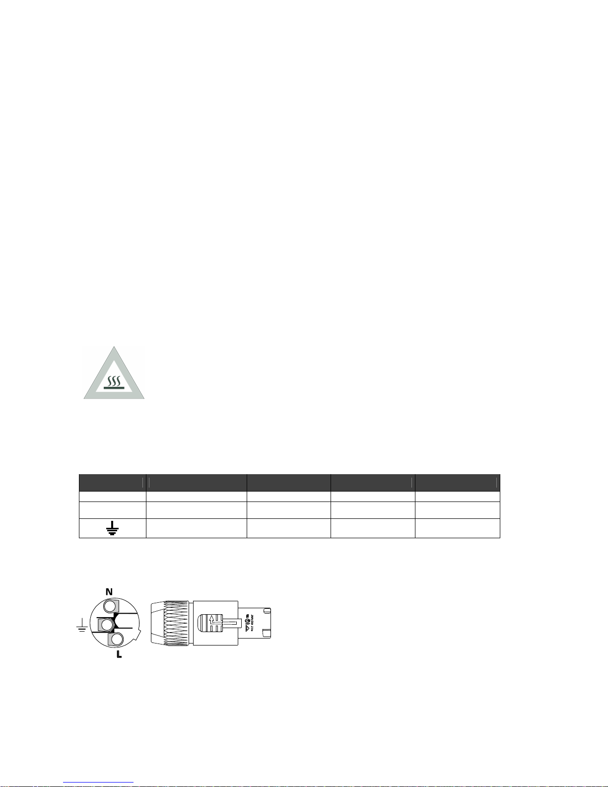
2.2
Power cable construction
Before installing the fixture check that the power supply cable AC is disconnected.
Wiring and connection work must be carried out by experienced qualified staff.
lass one equipment must be earthed (grounded)
Do not power Synthesis units with dimmers, as this could damage their on-board power supply
Before connecting the unit, make certain that the mains power supply is the same as indicated on the fixture’s
ID plate
The unit must be protected by a thermal/magnetic circuit-breaker
Symbol Pin U US UK
L Live Brown Yellow/Copper Red
N Neutral Blue Silver Black
Ground Yellow/Green Green Green
SGM Technology for lighting GB
Synthesis 11 User Manual 1.00
2.3
Installing the fixture on a support structure
Read the following safety information before proceeding with the installation of the fixture:
•FIXTURE NOT FOR DOMESTI USE.
•DO NOT INSTALL THE FIXTURE NEAR SOUR ES OF HEAT.
•INSTALL THE FIXTURE IN A WELL VENTILATED PLA E.
•AVOID BLO KING AIRINTAKES AND OUTPUTS.
•DO NOT USE THE FIXTURE:
In places subject to vibrations or bumps
In place subjet to temperatures of more than 45° or less than 2°
AVOID ANY KIND OF DIRE T ONTA T WITH THE LAMP.
•DO NOT PLA E THE UNIT ON INFLAMMABLE PARTS OR MATERIAL.
•PROTE T THE UNIT FROM EX ESSIVE HUMIDITY (IDEAL VALUES ARE BETWEEN 35 AND 80%).
•AVOID INFLAMMABLE LIQUIDS, WATER OR METALLI OBJE T ENTERING THE FIXTURE.
•DON’T LIFT THE FIXTURE HOLDING IT BY THE MOVING PARTS (HEAD).
•KEEP ANY INFLAMMABLE MATERIAL AT A DISTAN E OF AT LEAST 1,5M FROM THE FIXTURE.
•POSITION THE FIXTURE AT LEAST 1,5MT FORM THE SURFA E TO BE LIT.
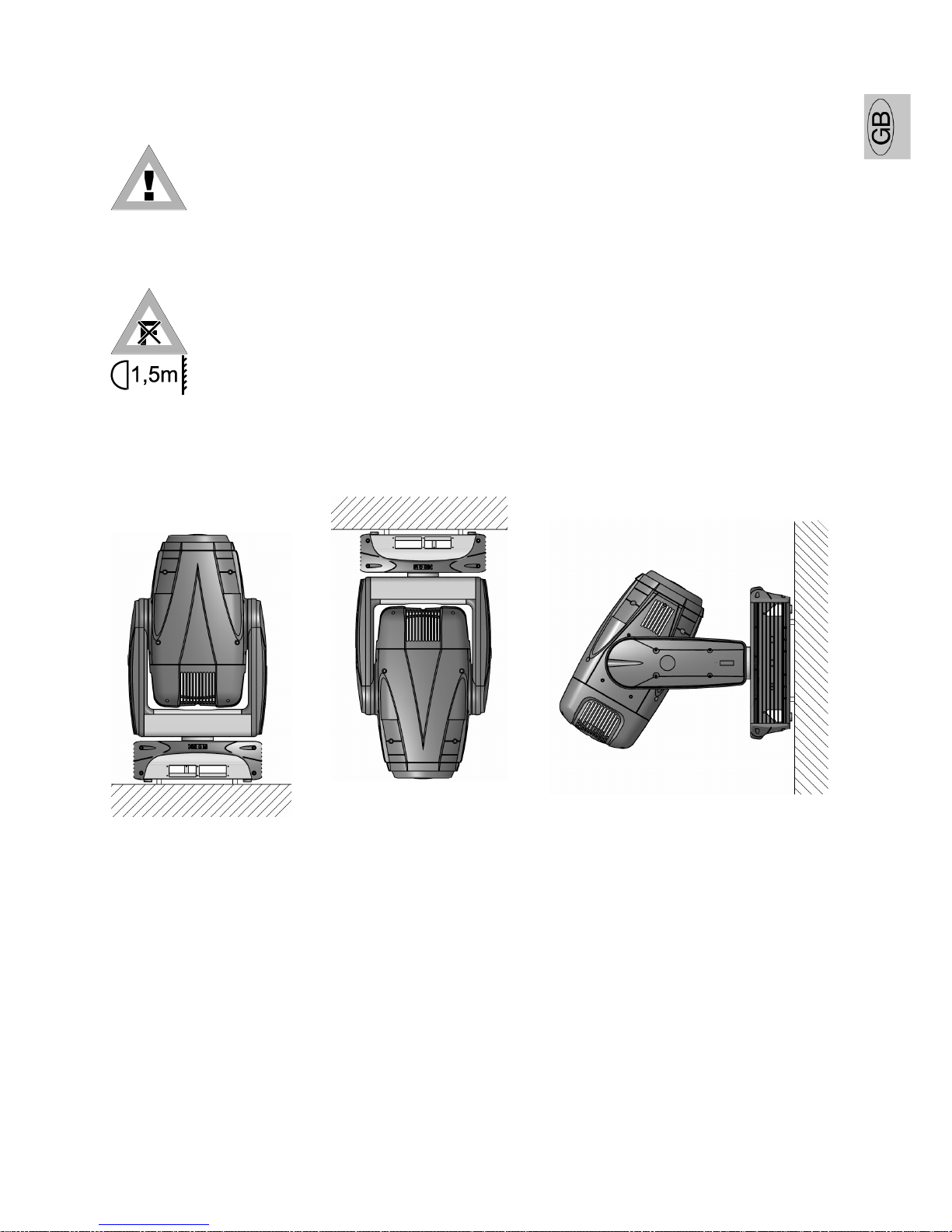
2.4
Positioning the fixture
an be installed in any position.
OK OK OK
GB SGM Technology for lighting
User Manual 1.00 12 Synthesis
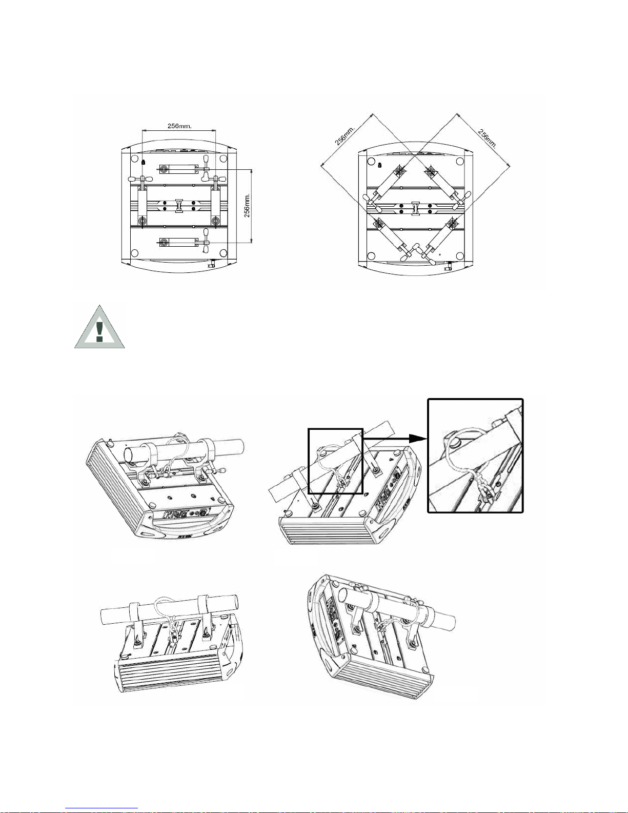
2.5
Fitting clamps
Always use two clamps to hang the fixture.
Attention: if the fixture is suspended from a truss suspended above ground or floor level, fix the
fixture with a steel safety cable.
Fix the fixture to the support structure using two safety chains fixed to the clamp (PI T. 2)
Don't fix the safety chain to the handles, use the safety chain fixing point located in the center of the base.
Pict. 1
Pict. 2
Pict. 3
Pict. 4
SGM Technology for lighting GB
Synthesis 13 User Manual 1.00
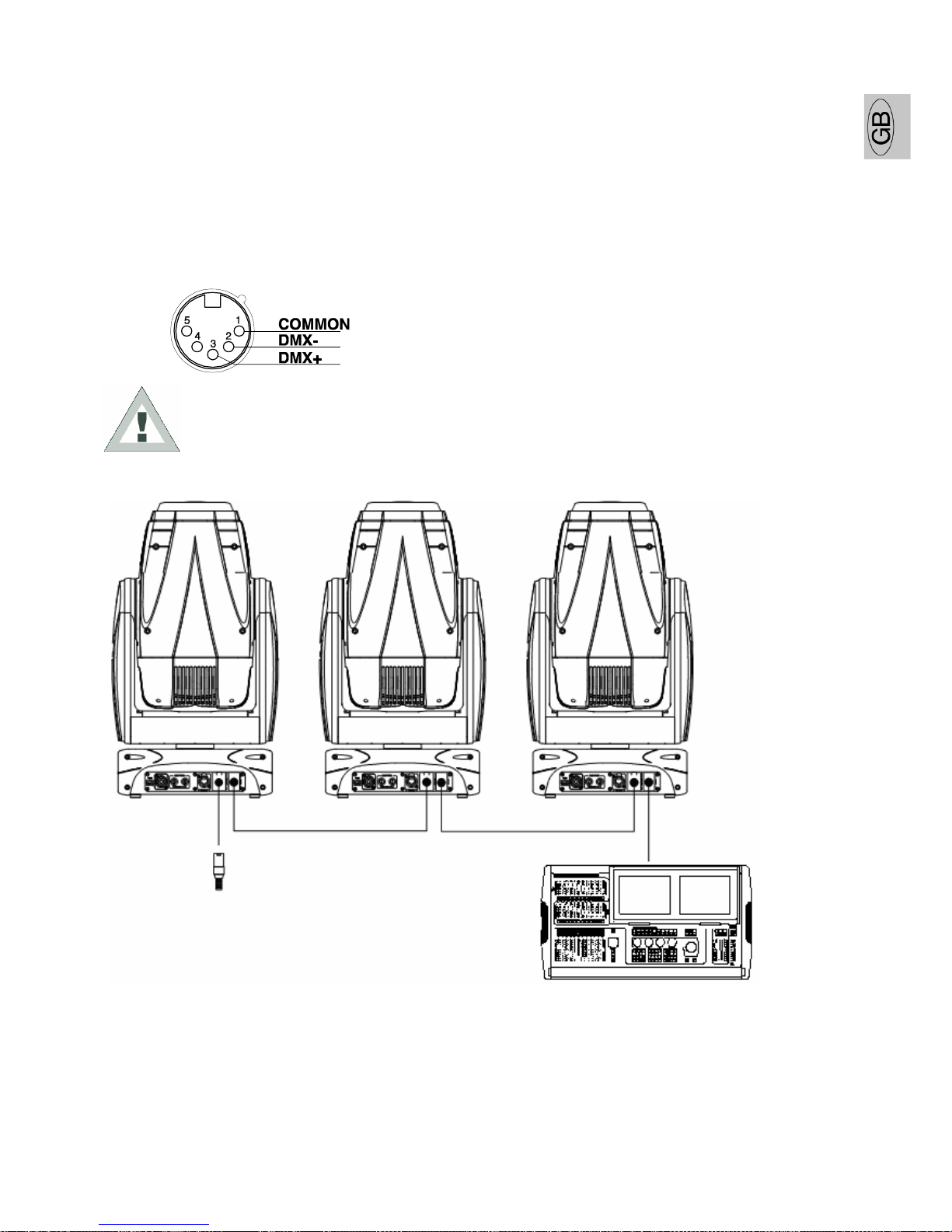
C
ONSTRUCTION OF TH SIGNAL CABL
Synthesis spot has a DMX 512 input fitted which uses standard XLR 5 Pins connector.
For the connection use screened cables having the EIA RS-485 specifications with the following features:
2 conductors plus screen
120 ohm impendance- low capacity
Max transmission speed 250 Kbaud.
C
ABL S CONN CTIONS
see illustration, taking care with the screen, which must
be connected to Pin 1
ATT NTION!!: the screened parts of the cable (sleeve) must N V R be connected to
the system's earth, as this would cause faulty fixture and controller operation.
xample of connection of the DMX line:
To avoid the risk of faulty operation, follow these indications:
Maximum cable length: 500 m
Max. N° of fixtures connected: 32 units
Cable runs: Avoid running cables alongside power supply lines.
Termination: A 120Ohm resistor between Pins 2 and 3 on the last fixture.
DMX Line
DMX Line
DMX Termination
(Last fixture)
GB SGM Technology for lighting
User Manual 1.00 14 Synthesis
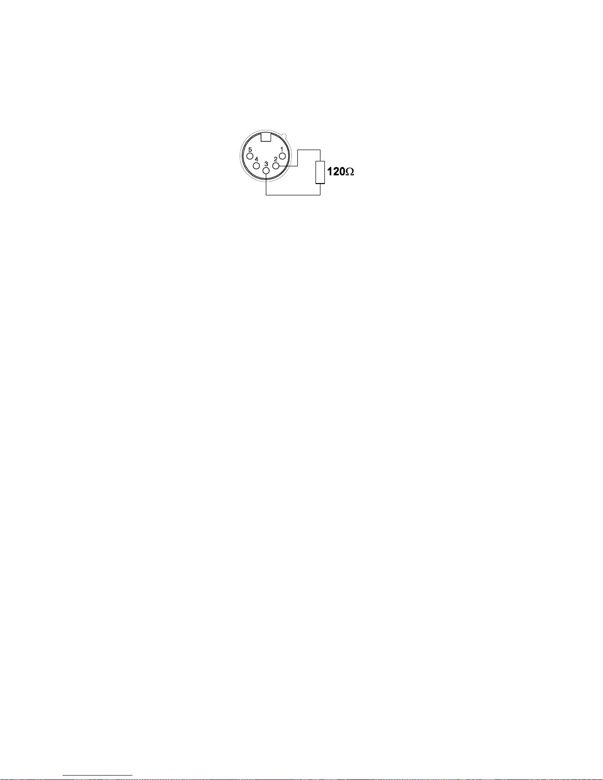
C
ONSTRUCTION OF TH DMX T RMINATION
The termination avoids the risk of DMX 512 signals being reflected back along the cable when they reaches the
end of the line:
under certain conditions and with certain cable lengths, this could cause them to cancel the original signals.
The termination is prepared by soldering a 120Ohm 1/4 W resistor between pins 2 and 3 of the 5-pin male XLR
connector (see diagram).
W
IR L SS
DMX
Synthesis is the world’s first moving head fixture fitted with wireless DMX as standard. It uses a technology based
on the idea of GSM, with a radius over 500 meters.
It has been widely tested in environments with WiFi, bluetooth, GPRS-UMTS signals, with excellent results.
If you want to use the wireless DMX protocol instead of the cable, proceed as follows:
For the wireless connection you need a specific transmitter (code 0097035)
Synthesis has 2 menus dedicated to the wireless: 1-WIRELESS LOG OFF and 2-WIRELESS
The procedure to activate the wireless communication is very easy:
1. Enter the LOG OFF menu and confirm the SET option. This function disables all the communications
previously enabled.
2. Set the WIRELESS on ON. This will enable a new communication.
3. Press the LOG key on the Transmitter to connect the receiver placed on the fixture to the wireless
transmitter.
RDM
(R
MOT
D
VIC
M
ANAG M NT
)
RDM stands for Remote Device Management. This is the colloquial name for the ANSI E1.20 standard in
development at ESTA
.
RDM is intended to allow bi-directional communication over the DMX512 cable. This will
occur on the twisted pair connected to pins 2 and 3. This same pair of wires is used to transmit data from the
console to the dimmers or moving lamps.
The large benefit of this approach as opposed to using the spare pins 4 and 5, is that RDM can be retrofitted to
installations wired with single pair cable.
RDM will provide the following benefits:
1. Ability for the console to set the base address of the lamp. There will no longer be a need for DIP switches.
2. Plug and Play. The console will be able to search all the DMX512 devices and then automatically patch them.
3. Fixture Personality: it will be possible for the console to use RDM to download personalities direct from the
moving lamp.
4. RDM devices can be firmware upgraded via the DMX signal.
5. RDM devices can send status and fault information back to the console.
6. By allowing bi-directional communication, it will be much easier to mix DMX installation with sophisticated
Ethernet protocols such as Art-Net and A N.
SGM Technology for lighting GB
Synthesis 15 User Manual 1.00
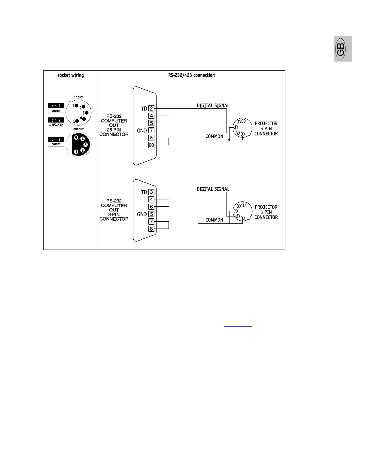
RS-232
CONN CTION
For this connection, use good quality screened coax cable (RG58 50Ohms) to avoid problems with signal
transmission and faulty fixture operation. onnectors must always be 5-pin XLRs.
Refer to the diagram for wiring.
2.6
Firmware updating
To update the firmware of the fixture you need:
USB-DMX Driver to install the new hardware.
USB-DMX cable to connect the unit to thel P .
Updated software version.
Please follow the below procedure to perform the updating:
1. Install the USB-DMX driver on the P you will use to download the software.
The driver and the instructions to install it will be available in our web site www.sgm.it
2. onnect the USB-DMX cable from the P to the fixture.
3. Download the software.
The software is composed by an upd file and a file with extention .exe, by opening the file .exe the updating will
be enabled automatically.
This software won’t update the microprocessors of the fans boards fitted in the head, of the ballast and the PF .
It will be possible to download the software from our web site www.sgm.it.

GB SGM Technology for lighting
User Manual 1.00 16 Synthesis
2.7
Access to internal components
All work must ALWAYS be carried out by qualified technical personnel.
ATT NTION!! make certain that the fixture is switched off and that there is no risk of
burns due to high component temperature (wait at least 30 minutes after switching
off)
To access internal components, proceed as follows:
1. Place the head of the Synthesis in a vertical position (Fig.1)
2. Use a screwdriver to loosen screws 1, 2, 3 and 4 (Fig.1)
3. Extract the cover "A" (Fig.2) outwards.
If necessary, repeat the same procedure for cover "B"
Pict. 1
Pict. 2
SGM Technology for lighting GB
Synthesis 17 User Manual 1.00
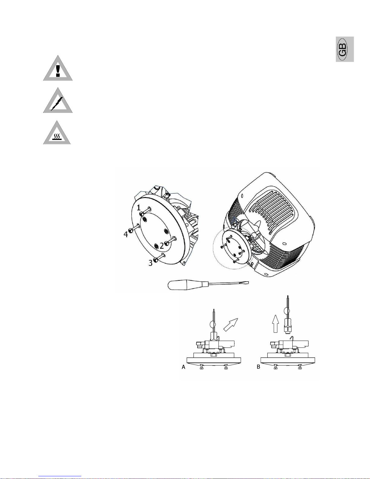
I
NSTALLING
/
R PLACING TH LAMP
ATT NTION! This fixture is designed exclusively for use with Osram HTI 700W/S /75
lamps. N V R US ANY OTH R TYP S OF LAMPS.
DIS ONNE T THE POWER SUPPLY BEFORE ARRYING OUT ANY WORK ON THE FIXTURE.
MAKE ERTAIN THAT THE FIXTURE IS OFF AND THE TEMPERATURE OF THE OMPONENTS AN'T AUSE
BURNS (WAIT AT L AST 30 MINUT S AFT R SWITCHING OFF).
NEVER ARRY OUT ANY WORK IF THE FIXTURE DOESN'T HAVE ITS PROTE TIVE OVERS OR ITS LENSES
ARE DAMAGED.DIS HARGE LAMPS AN EXPLODE.
NEVER LOOK DIRE TLY AT THE LAMP WHEN IT'S LIT - DIS HARGE LAMPS EMIT UV RAYS WHI H ARE
DANGEROUS FOR SIGHT.
Inside the fixture's moving head, there is an optical system. Follow the herebelow instructions when installing or
replacing a lamp.
Pict. 3
1. Through a screwdriver untighten the screws indicated in picture 1 with numbers 1.2.3.4.
2. Remove the rear cover where the socket is located, as indicated in picture 2.
3. Pull the lamp fixing spring as indicated in picture 3 and at the same time remove the lamp from the lamp
holder as indicated in picture 3B.
4. Never touch the lamp bulb bare handed. Always use a cloth or gloves to handle the lamp during insertion or
removal operations.
Pict
. 1
Pict. 2
GB SGM Technology for lighting
User Manual 1.00 18 Synthesis
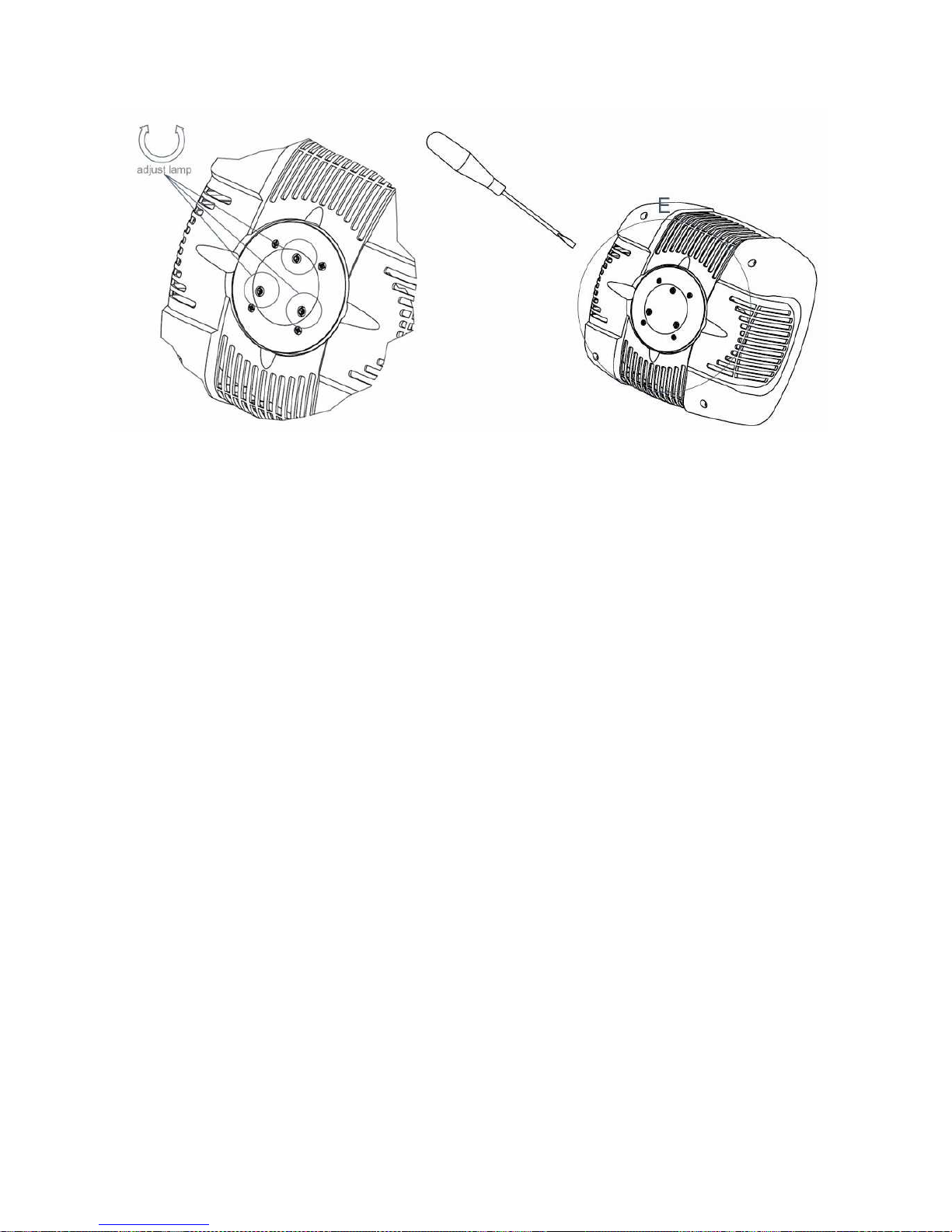
L
AMP ALIGNM NT
When replacing the lamp with a new one, align the lamp with the optical system to obtain the max uniformity and
luminous performance by the projection.
1. Install the new lamp close the fixture and switch it on
2. onnect the fixture to a lighting console.
3. Point the fixture at a flat surface (if possible white or light colored) at least three metres from the fixture.
4. Set the control channels to obtain a white beam. Then open the IRIS, set the DIMMER fully open, FUO O
correctly and do not project GOBOS or OLORS.
5. Use screws 1, 2 and-3 to align the lamp until an evenly projected light beam is obtained, with no shadows or
zones which are brighter than others.
1
3
2
Other manuals for Synthesis Wash 700
1
Table of contents
Other SGM Light Fixture manuals


Popular Light Fixture manuals by other brands


Show Tec
Show Tec Infinity iW-1915 RGBW Wash manual

MrHeater
MrHeater MHGLLP B Operating instructions and owner's manual

HAMPTON BAY
HAMPTON BAY 79130 Use and care guide

ARTFOX Lighting
ARTFOX Lighting LED Beam Wash 19E user manual

Desisti
Desisti LEONARDO 310 instruction manual

Lightolier
Lightolier PRISTINE T2 installation instructions