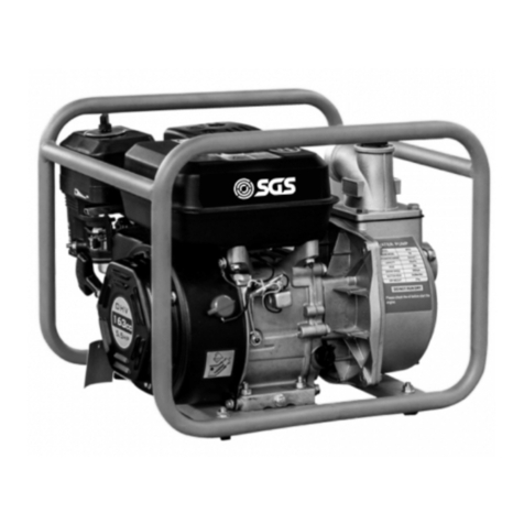
SGS SWPT80 User manual

FOR YOUR SAFETY
PLEASE READ THESE INSTRUCTIONS CAREFULLY
AND RETAIN THEM FOR FUTURE USE.
OWNER’S MANUAL
SWPT80 PETROL
TRASH WATER PUMP

PAGE 3
PAGE 2
SPECIFICATION
Product Code SWPT80
Suction Port 80mm
Max Head 28m
Noise Emission 110 dB (Lwa)
WARNING
WARNING
Read and understand instructions before use.
Always wear eye/face and hand protection.
Always observe all safety precautions for the han-
dling of fuel
As with all machinery, there are certain hazards
involved with its operation and use. Exercising cau-
tion will reduce the risk of personal injury.
1. ALWAYS ensure that the pump is properly positioned where
necessary to prevent it from moving during operation, and that
the immediate area surrounding the pump is kept clear.
2. ALWAYS ensure the unit cannot be started inadvertently by us-
ing the ON/OFF switch whenever carrying out maintenance or
making adjustments.
3. ALWAYS use the strainer connected to the suction hose, to pre-
vent stones and other solids from being drawn up, which could
cause severe damage to the pump.
4. ALWAYS keep the machine itself dry and well clear of water
discharge.
5. ALWAYS use only replacement parts supplied by the manufac-
turer. The use of non-standard parts could be hazardous.
6. ALWAYS use at least 1ft (300mm) of flexible hose to make
plumbing connections to the pump. Rigid piping may put stress
on the pump, causing damage. If rigid piping must be used, it
should be supported so as to eliminate stress on the pump.
7. NEVER refuel the engine whilst it is running, and allow the en-
gine to cool sufficiently before refuelling.
8. NEVER use for pumping petrol (or other flammable liquids),
or corrosive chemicals. These pumps are designed to pump
WATER ONLY.
9. NEVER operate an engine driven unit in an explosive atmos-
phere, near combustible materials, or where there is insufficient
ventilation.
10. NEVER allow children to use this machine.
11. NEVER run the pump dry. Always fill the pump with water be-
fore starting.
WWW.SGS-ENGINEERING.COM

PAGE 5
PAGE 4
BEFORE USE
Operating the pump dry will destroy the pump
seal. If the pump has been operated dry, stop the
engine immediately, and allow the pump to cool
before priming
This pump is not supplied with engine oil or fuel. Use any engine
oil of SAE 10-30 rating unless operating at very high or low ambi-
ent temperatures.
1. Remove the filler plug/dipstick.
2. Fill the unit with oil until visible inside.
3. Check the level by inserting the dipstick
back into the filler tube and checking the
level is within the indicated range. If cor-
rect replace the dipstick/filler cap.
NOTE: The unit is fitted with a low oil sensor which will stop the
engine if the oil level drops below the safe level to avoid internal
damage. Refer to troubleshooting section.
ADDING FUEL
Fill the fuel tank with unleaded petrol or check the level by open-
ing the fuel cap and topping up as required. Located within the
fuel tank is a strainer. Check this filter periodically and remove any
contaminants which may have accumulated. Do not fill above the
fuel strainer shoulder. After refuelling, tighten the fuel filler
cap securely. Use unleaded petrol with a pump octane rating
of 86 or higher.
WARNING: WIPE UP ANY SPILT FUEL BEFORE
RUNNING THE PUMP. ALLOW THE ENGINE TO
COOL DOWN BEFORE REFUELLING
WWW.SGS-ENGINEERING.COM

PAGE 7
PAGE 6
STARTING THE ENGINE
1. Prime the pump
2. Move the fuel level to the ON position
3. To start a cold engine, move the choke lever to the CLOSED
position. To restart a warm engine, leave the choke lever in the
OPEN position.
STARTING THE ENGINE
4. Move the throttle lever away from the SLOW position about
1/3 of the way toward the FAST position.
5. Turn the ignition switch to the ON position.
WWW.SGS-ENGINEERING.COM

PAGE 9
PAGE 8
STARTING THE ENGINE
6. Pull the recoil starter grip lightly until-resistance is felt, then
pull it briskly. Do not allow the recoil starter grip to snap back
against the engine. Return it gently to prevent damage to the
starter.
7. If the choke lever was moved to the CLOSED position to start
the engine, gradually move it to the OPEN position as the en-
gine warms up.
SETTING THE ENGINE SPEED
8. After starting the engine, move the throttle lever to the FAST
position for self-priming, and check pump output. Pump output
is controlled by adjusting engine speed. Moving the throttle
lever in the FAST direction will increase pump output, and mov-
ing the throttle lever in the SLOW direction will decrease pump
output.
9. To stop the engine in an emergency, simply turn the ignition
switch to the OFF position. Under normal conditions, use the
following procedure.
a. Move the throttle lever to the SLOW position.
b. Turn the ignition switch to the OFF position.
c. Turn the fuel valve lever to the OFF position.
After use, remove the pump drain plug, and drain the pump
chamber. Remove the filler cap, and flush the pump chamber
with clean, fresh water. Allow the water to drain from the pump
chamber, then re-install the filler cap and drain plug.
WWW.SGS-ENGINEERING.COM

PAGE 11
PAGE 10
GENERAL USE OF THE PUMP
1. Connect the suction and discharge hoses to the pump hou-
ing using the hose clamps and gaskets supplied to achieve an
airtight seal. There must be no damage of any kind to the hoses
which must be well protected and supported.
NOTE: Hoses or pipes should be supported independently and not
carried by the pump.
IMPORTANT: An air leak in the suction line will prevent priming,
and reduce the capacity of the pump.
2. Pay particular attention to the following:
a. Always ensure the hose adaptor gasket is in place, and
correctly fitted.
b. Always use a flexible hose at the pump body connection,
of at least 1ft (300mm).
c. Keep all pipes/hoses as short and straight as possible,
and avoid sharp bends.
d. If a flexible hose must be laid across a roadway, protect it
with planking.
e. Ensure there is adequate drainage for the discharged
water.
(Instantaneous shut off pressure, applied when a vehicle runs across
an unprotected hose, will cause “hydraulic shock”, which can dam-
age the pump and/or the hose).
GENERAL USE OF THE PUMP
3. Attach the suction strainer to the end of suction hose using a
further hose clamp, to prevent large stones etc, from being
drawn up which could cause severe damage. Keep the strainer-
clean. If it is likely to clog with dirt or debris, proceed by either:
a. Preparing a bed of stones on which to rest the strainer.
b. Tying the strainer so that it stays off the bottom of the
pit, pond or excavation.
c. Tie the strainer inside a basket or bucket.
4. Remove the filler plug on top of the pump case and prime the
pump with water, leaving no air gap. Remember the pump
is self-priming only when the pump is filled. It will prime and
re-prime itself without refilling. Refilling is necessary only if the
pump has been drained or if the water has been lost. Never al-
low the pump to run dry.
5. Properly fuelled and lubricated your pump will run without at-
tention.
WWW.SGS-ENGINEERING.COM

PAGE 13
PAGE 12
MAINTENANCE
1. Always maintain the pump in a clean condition, checking regu-
larly for loose bolts etc.
2. Clean the air filter once every 50 hours of use (or more often in
unusually dusty conditions) as follows. Clean the foam filter ele-
ment with domestic detergents and clean the mesh element by
knocking against a solid object or blow out any dust with a high
pressure air jet. Never operate the pump without the air cleaner
installed as this would cause premature wear to the engine.
3. Replace the spark plug after the first month or every 50 hours
of use. Check when installing that the spark plug has the cor-
rect clearance by measuring with a feeler gauge and adjusting
the side electrode as required. Clearance should be 0.70-
0.80mm. The recommended spark plug is RK34200/168F.
CHANGING THE OIL
The oil in the engine should be changed after the first 20 hours use
and thereafter every 6 months or 100 running hours. Remove the
dipstick and drain plug and then drain the oil. Re-fill and check the
level.
ENVIRONMENTAL PROTECTION
One of the most damaging sources of pollution is oil. Do not throw
away used oil with domestic refuse or flush down a sink or drain.
Take it to your local waste disposal site.
STORAGE & HANDLING
After use, drain the pump body whenever there is danger of free-
ing, and if the pump has been used with contaminated or salty
water, It should be thoroughly flushed with clean water following
use, both inside and out and drained before replacing the drain
plug. Always transport the pump with the fuel cock turned off and
keep the unit level to prevent any fuel from spilling.
If the pump is not to be used for some time, it should be flushed
thoroughly with clean water, and drained completely before storing
in a clean dry environment. Additionally, it should be prepared
as follows:
1. Drain the fuel tank and carburettor completely by opening the
drain plug in the carburettor float chamber and draining all
remaining fuel into a suitable container ensuring the fuel shutoff
valve is open.
2. Remove the spark plug, and pour 2-3 teaspoons of light oil into
the cylinder through the spark plug hole.
3. Pull the starter recoil rope slowly 2 or 3 times so that the oil is
deposited on the cylinder walls and replace the spark plug. For
longer term storage, use the starter to turn the engine until
the triangle mark on the starter wheel lines up with the starter
screw hole. In this location both the inlet and exhaust valves are
closed which may prevent the engine from suffering internal
corrosion during storage.
WWW.SGS-ENGINEERING.COM

PAGE 15
PAGE 14
TROUBLESHOOTING STORAGE & HANDLING
PROBLEM CAUSE SOLUTION
Engine fails to start Lack of fuel in tank. Fill tank as necessary.
No fuel reaching carbu-
retor.
Fuel cock isolated. Turn
on fuel shut-off valve.
Engine switch is in the
OFF position.
Set engine switch to the
ON position.
Lack of spark at the
spark plug.
Lack of spark at the
spark plug.
Engine stops and will
not restart
Lack of oil in engine
causing ‘Low Oil Pro-
tection’ sensor to stop
engine from running.
Fill oil reservoir as neces-
sary.
Pump fails to prime Priming chamber not
filled correctly.
Fill priming chamber
leaving no air gap.
Air leaks through the
suction line joints (dam-
aged hose, broken hose
clamps, broken / ill-
fitting gasket).
Carry out repairs as
necessary/check, repair
connections as required.
Blocked inlet hose. Clean strainer & ensure
it is not submerged in
mud or sediment etc.
Ensure there are no kinks
in delivery hose.
Engine speed too low. Increase engine speed.
Damaged impeller. Renew impeller after
dismantling pump.
Air leaks through dam-
aged seal.
Renew seal.
PROBLEM CAUSE SOLUTION
Low output from pump Engine speed too low Increase engine speed.
Impeller clogged Clean strainer and en-
sure it is not submerged
in mud or sediment etc.
Suction or delivery line
obstructed
Remove obstruction and
ensure there are no kinks
in delivery line.
High friction losses in
the suction line
Avoid un-necessary
curves, restrictions or
valves.
Suction lift too high Set pump as close as
possible to the level of
the liquid to be pumped.
Congested material
inside pump
Dismantle pump & clean
out.
Damaged impeller Dismantle pump and
renew impeller.
WWW.SGS-ENGINEERING.COM

PAGE 17
PAGE 16
PARTS DIAGRAM PARTS LIST
No. PART NAME QTY PART No.
1 Pump Body 1 902328
2 “O” Ring 5x2.65 2 902329
3 Whorl Plug 2 902330
4 T type screw 1 902331
5 “O” Ring 5x2.65 1 902332
6 Check valve 1 902333
7 Diffuser 1 902334
8 Impeller 1 902303
9 Spring column pin 2 902335
10 “O” Ring 125 x 2.65 1 902336
11 “O” Ring 260 x 5 1 902337
12 Pump cover 1 902338
13 Mechanical seal 1 902339
14 Hexangular hose joint 1 902340
15 Strainer 1 902341
16 Rubber feet 4 902291
17 Bolt M8X20 4 900393
18 Flange Nut M8 4 900520
19 Flange hd hex. bolt M8X20 4 902265
20 Gasoline engine 7.0hp 1 902294
21 Frame 1 902321
WWW.SGS-ENGINEERING.COM

EC Declaration of Conformity
This is an important document and should be retained
MANUFACTURER’S NAME:
TYPE OF EQUIPMENT:
PART NUMBER:
I, the undersigned, hereby declare that the equipment specied above con-
forms to the above European Communities Directive(s) and Standard(s).
PLACE:
DATE: (Signature)
Robert Wyatt
Company Secretary
Derby, UK
24th MAY 2018
SGS Engineering (UK) Ltd
West Side Park
Raynesway
Derby, DE21 7AZ
Water Pump
SWP50 / SWP80 / SWPT80
2006/42/EC Machinery directive
2004/108/EC EMC directive
73/23/EC The low voltage directive
97/68/EC NRMM emissions directive
2000/14/EC Noise emissions directive
APPLICATION OF EC COUNCIL DIRECTIVES / STANDARD:
Table of contents
Other SGS Water Pump manuals
Popular Water Pump manuals by other brands

Pentair
Pentair SHURFLO installation manual

Grundfos
Grundfos MAGNA3 25-100 (N) Installation and operating instructions

Fountain TECH
Fountain TECH FT-130 user guide

Reefe
Reefe VMR5-16 instruction manual

GORMAN-RUPP PUMPS
GORMAN-RUPP PUMPS PA6C60-4045D/S1 Installation, operation, and maintenance manual with parts list

Power-flo
Power-flo PF15ICU Installation, service & parts manual

Bühler technologies
Bühler technologies P2.x ATEX instructions

STA-RITE
STA-RITE Boost-Rite S4P100M manual

Kessel
Kessel 85 101 Installation, operation and maintenance instructions

Milton Roy
Milton Roy LMI P1 Basic Manual

Oase
Oase ProMax MudDrain 7000 operating instructions

Trebor
Trebor Mega 120D Operation & maintenance manual