ShadeFX Freestanding Canopy User manual

Freestanding Canopy
Assembly Guide

ShadeFX Installation Guide 2
REV. 03/2021
Table of Contents
Introduction
How it Works 3
The Importance of Proper Assembly 3
Proper Handling 3
System Components
Base Assemblies 4
Structure Assembly 5
Track and Canopy Assemblies 5
Recommended Tools 6
Hardware 7
Assembly
Step 1: Locating, Securing, and Leveling the Base 10
Step 2: Assembling the Structure 14
Step 3: Attaching the Canopy 18
Post-installation
Rotating the Canopy 20
Winter Storage 21
Wind 21
Improper Uses of the Product 21
Lubricants 21

ShadeFX Installation Guide 3
REV. 03/2021
Introduction
How it Works
All ShadeFX systems utilize the patented single-track drive system. Fabric panels of the canopy assembly are
extended or retracted as the lead carrier and wing travel along the drive beam.
The Importance of Proper Assembly
Proper assembly will preserve the life of your ShadeFX Retractable Freestanding Canopy. Inadequate assembly
may result in avoidable and expedited wear on the system’s components. The assembly instructions outlined in
this guide are intended to assist with the successful deployment of your Freestanding Canopy.
It is recommended that a complete review of the assembly guide be conducted prior to assembly. If there are
questions regarding assembly that are not addressed in the guide, please contact ShadeFX before continuing.
Proper Handling
Proper care must be taken when handling the product during assembly as contact with hard, sharp or abrasive
surfaces could result in deformation, scratches or rips in the fabric and components of the system.
It is important to handle your canopy assembly with care, especially when lifting the canopy onto the structure. It
is recommended to work in a group of at least two people.
Questions
ShadeFX Retractable Freestanding Canopies are a unique product with limited comparable oerings. Whether you
are an experienced contractor or homeowner assembling the system for the rst time, questions may arise.
ShadeFX Canopies: (855) 509-5509

ShadeFX Installation Guide4
REV. 03/2021
System Components
Each ShadeFX Freestanding Canopy will include a base assembly, structure assembly, track assembly and a
canopy assembly. The nal product will resemble the following image.
Base Assemblies
Concrete Base Wood Base

ShadeFX Installation Guide 5
REV. 03/2021
Structure Assembly
Track and Canopy Assemblies

ShadeFX Installation Guide6
REV. 03/2021
Recommended Tools
The tools listed below are recommended to facilitate an ecient and eective assembly. Certain tools may be
substituted.
• Stepladder (x2)
• Tape or laser measure
• Level
• Pencil, marker (for base plate location marking)
• 9/16” Wrench
• 7/32” Socket Head Bit or Allen Key
• Rubber Mallet
• Chalk or string line
• If Wood Base Option: Drill and #2 Robertson (Square) drive
• If Concrete Base Option: Concrete drill, 9/16” socket drive, and 5/16” concrete drill bit

ShadeFX Installation Guide 7
REV. 03/2021
Hardware
Hardware is dependent on the number of units and base option selected. Hardware is categorized into four
groupings: general hardware, base assembly hardware, structure assembly hardware and track assembly
hardware.
General Hardware
A Removable Canopy Handle to extend and retract the canopy is included with each order. Gravity Clips “G-Clips”
are also included with every canopy to attach the canopy assembly to the track assembly. The number of G-Clips
is dependent on track length. Quantities listed below are on a per canopy basis.
Item Quantity Per Canopy Drawing
Removable Canopy Handle* x1
Gravity Clip “G-Clip”
x10 (8’ Track Length)
x12 (10’ Track Length)
x16 (12’ Track Length)
x18 (14’ Track Length)
x20 (16’ Track Length)
*Only one handle will be provided per order
Base Assembly Hardware
Base assembly hardware is dependent on the type of base selected and number of canopies purchased.
Quantities listed below are on a per post basis.
Concrete Base Hardware
Item Quantity Per Canopy Drawing
3/8” x 5” LDT Screw Anchor x4
3/8”x16 x 1” Flat Socket Cap
Screw x8

ShadeFX Installation Guide8
REV. 03/2021
Wood Base Hardware
Item Quantity Per Canopy Drawing
#10-8 x 4” Wood Screw x16
3/8”x16 x 1” Flat Socket Cap
Screw x8
Structure Assembly Hardware
Structure assembly hardware quantity is dependent on the number of canopies purchased. Quantities listed
below are on a per post basis.
Item Quantity Per Post Drawing
3/8” Washer x4
3/8”-16 Hex Nut x4

ShadeFX Installation Guide 9
REV. 03/2021
Track Assembly Hardware
Track assembly hardware quantity is dependent on the number of units purchased. Quantities listed below are on
a per canopy basis.
Item Quantity Per Canopy Drawing
Rotation Plate x2
3/8”-16 x 1-1/2” Flat Socket Cap
Screw x8
3/8”-16 x 1-1/2” Hex Bolt x4
3/8”-16 Hex Nut x2
3/8” Washer x4

ShadeFX Installation Guide10
REV. 03/2021
Assembly
The following instructions are intended to assist with the assembly of the Retractable Freestanding Canopy.
Please contact ShadeFX if you require clarication of any of the steps listed below.
The assembly of the Freestanding Canopy consists of three major steps:
1. Locating, Securing and Leveling the Base
2. Assembling the Structure
3. Attaching the Canopy
The steps of Locating, Securing and Leveling the Base will vary depending on the base type selected
(Concrete/Wood). Assembling the Structure and Attaching the Canopy remain constant across both base
options.
Step 1: Locating, Securing and Leveling the Base
In Step 1 you will connect the post to the base, locate & align the bases to each other and level & secure the
bases to the mounting surface.
Concrete Base / Wood Base
Concrete and wood bases follow the same set of steps. If wood base is selected, the deck must be reinforced
at base locations to ensure all screws are engaged in structural wood. Contact ShadeFX if deck reinforcement
recommendations are needed.
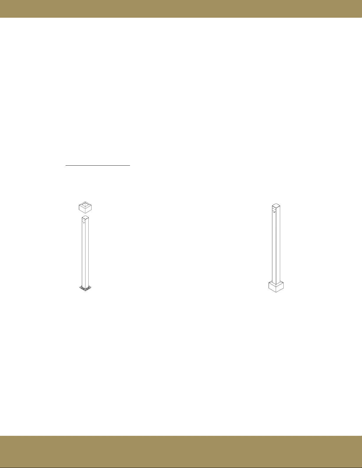
Connecting the Post to the Base
i. Connect post to base using 3/8”-16 x 1” at head socket screws (x8). The post plate aligns with
the recessed cutout in the base. Repeat for other post(s).

ShadeFX Installation Guide 11
REV. 03/2021
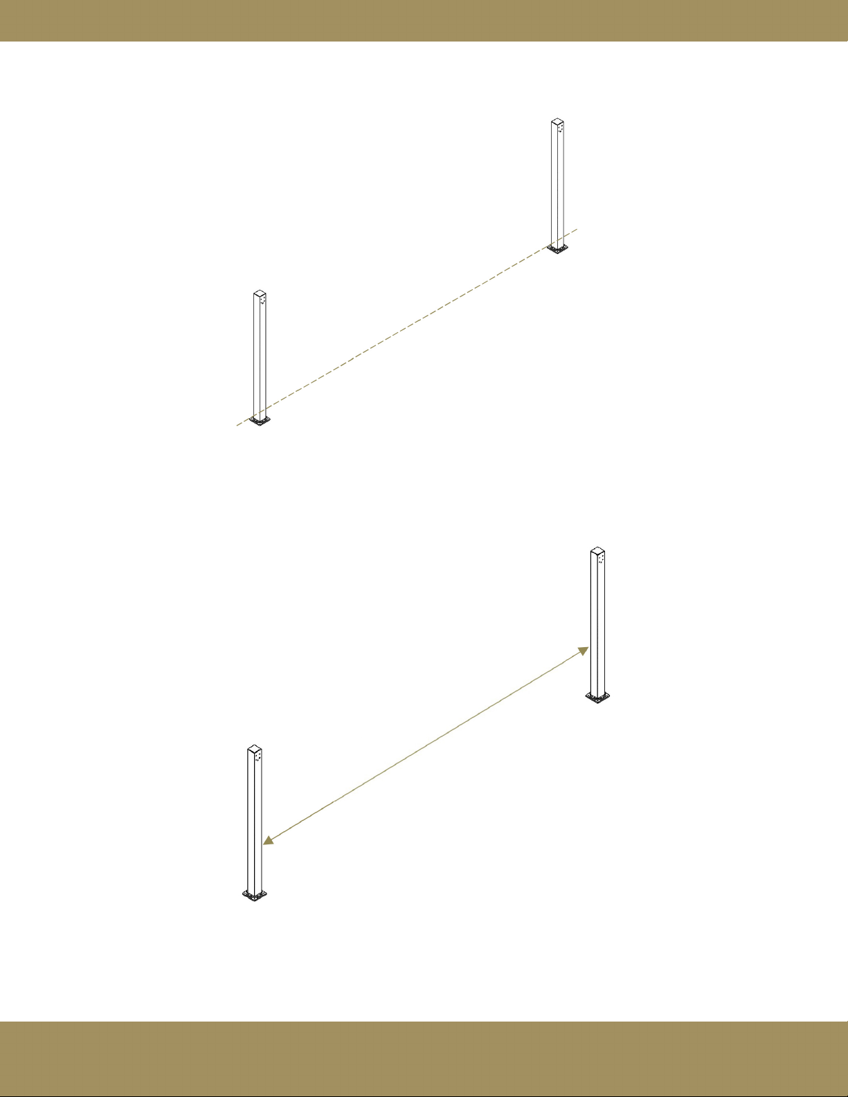
Locating and Aligning the Bases
i. Ensure the front face of the post is facing forward.
ii. Determine the required distance between the bases for CONCRETE mounting by subtracting
2-3/4” from the total track supporting beam length (track supporting beam + rotation plate).
Ex: for a 16’ track the required distance between bases is 189-1/4” (192”-2-3/4”)
Determine the required distance between the bases for WOOD mounting by subtracting 5-3/4” from
the total track supporting beam length (track supporting beam + rotation plate).
Ex: for a 16’ track the required distance between wood bases is 186-1/4” (192”-5-3/4”)
Ensure the back (or front) of the bases are co-linear by dropping a chalk line.
Front Face of Post
Inside Back Distance
Inside Front Distance
ShadeFX Installation Guide12
REV. 03/2021
iii. Once the bases are aligned the distance between the inside of the posts should equal the total track
supporting beam length (track supporting beam + rotation plate) +1/4”.
Ex: for a 16’ track the inside to inside post distance should be 192-1/4” (192”+1/4”)
iv. Using a marker or pencil, mark the hole locations through the base plate onto the surface below.
Inside Post-to-Inside Post Distance
ShadeFX Installation Guide 13
REV. 03/2021
v. Pre-drill holes on marked locations:
Concrete: use concrete drill and 5/16” concrete drill bit
Wood: use regular drill and #2 Robertson (Square) drive
vi. Mount base plate/post assembly to the ground using the predrilled holes and the provided fasteners.
Concrete: use a high torque drill and a 7/16” socket bit
If the fasteners are too dicult for the drill to tighten use a socket wrench and
the 7/16” socket bit and tighten the fasteners manually.
Wood: use a regular drill and #2 Robertson (square) bit
vii. For Concrete Base only:
Slide the post skirts over the posts so that they cover the baseplates.
ShadeFX Installation Guide14
REV. 03/2021
Step 2: Assembling the structure
In Step 2, you will assemble the structure that supports the canopy by attaching the arm to the post, attaching the rotation
plate to the track supporting beam and mounting the track supporting beam to the posts. Step 2 is constant across all
three base options.
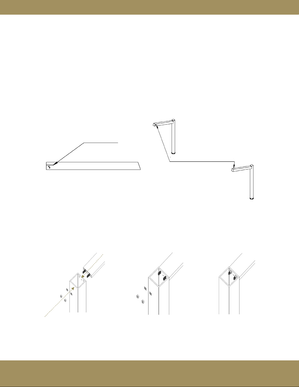
Attaching the Arms to the Post
i. The cut faces (see below) should be facing each other when installed on posts. Ensure the arms are
angled upwards when installing.
Secure arms in place by installing washers (x4 per arm) and 3/8”-16 hex nuts (x4 per arm) from inside
the posts.
“Cut face”
“Cut face” facing inwards

ShadeFX Installation Guide 15
REV. 03/2021
Attaching the Rotation Plate to the Track Supporting Beam
ii. Attach rotation plate onto the track supporting beam by rst inserting the 3/8”-16 x 1-1/2” hex bolt
through the slot hole.
Then, secure the rotation plate onto the track supporting beam using 3/8”-16 x 1-1/2” at socket
cap screws (x4). Add a 3/8” washer and loosely thread a 3/16” nut until the nut is just on the
protruding thread. Repeat on the other side of the track supporting beam.
Ensure protruding threads on both rotation plates are adjacent to the same face. Ex: Protruding
threads adjacent to Face “A”
Face “A”

ShadeFX Installation Guide16
REV. 03/2021
Mounting the Track Supporting Beam to the Posts
iii. With two ladders set up in front of each arm, two laborers are to simultaneously raise the track
supporting beam to align the protruding threads with the slot in the arms. Slide the protruding thread
into the arm slots such that the existing threads (with nuts) protruding from the plates are
inserted rst. Refer to the image below for insertion direction.
iv. Set desired track angle (at orientation shown below). This orientation can be changed at any time
(see ‘Post Assembly’). Insert 3/8”-16 x 1-1/2” hex bolt with 3/8” washer into the plate hole when
the appropriate hole in the post is aligned. Repeat on other side of the track supporting beam.
20º from Horizontal
(Tilted Backwards)
Horizontal
20º from Horizontal
(Tilted Backwards)

ShadeFX Installation Guide 17
REV. 03/2021
v. Ensure both the bolt inserted in Step 2-iv as well as the nut fastened onto the protruding thread in
Step 2-ii are tightened fully and is done on both ends of the track supporting beam.
vi. Press post caps into top of arms and top of posts. Use a rubber mallet if required.

ShadeFX Installation Guide18
REV. 03/2021
Step 3: Attaching the Canopy
In Step 3 you will connect your canopy to the structure. Each wing is to be inserted into a carrier assembly and
secured using gravity clips (G-clips) (x2). Start with a lead carrier (has a protruding eye bolt), then all of the normal
carriers, then end with the other lead carrier. Ensure that the rst wing (lead wing) inserted into a lead carrier is the
rst wing on the fabric.
Note: Do not dispose of the packaging bag as it can be used for winter storage of the canopy.
i. Raise wing into carrier assembly. Align holes in wing with holes in carrier assembly.
Lead Wing
Lead Carrier

ShadeFX Installation Guide 19
REV. 03/2021
ii. Once holes are aligned, insert G-clips.
iii. Rotate G-clips downward until they lock into position.
Notice the direction of the G-clips on each side of the drive beam are dierent.

ShadeFX Installation Guide20
REV. 03/2021
Post-installation
Rotating the Canopy
Changing the canopy orientation requires the removal of the post caps on the arms. This can be done by inserting
a at screwdriver into the small slot in the post cap to pry the cap o.
Completely remove the hex bolt while being careful not to drop the washer
Hold the track supporting beam and slowly release the nut on the protruding thread until rotation is possible
Tighten nut and bolt to secure in place (Canopy Tilted Forward position shown above)
Rotation can be done with the canopy still attached but it is recommended that it be retracted in the middle of the
track supporting beam.
Table of contents
Popular Tent manuals by other brands


Coleman
Coleman Sundome 9180B705 instructions

Vortex
Vortex 3300 Louvre Pergola owner's manual

Eagle Peak
Eagle Peak 6ftx4ft Foldable Greenhouse Canopy instruction manual

MSR
MSR NOOK GEAR SHED Assembly instructions

Big Agnes
Big Agnes Mine Mountain Series String Ridge 2 Setup instructions

Summit Racing
Summit Racing GSA-M1014 Setup instructions


