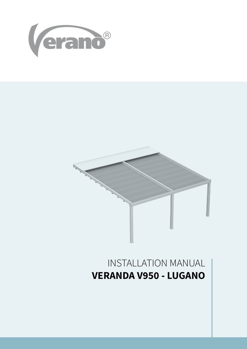
Shadowspec Unity User manual

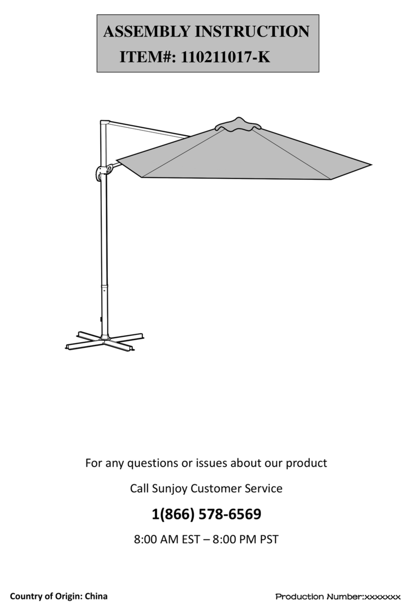
MULTI CANOPY CANTILEVER UMBRELLA
SHADOWSPEC UNITY™
www.shadowspec.com
P01/23
OWNERS MANUAL
Installation, Operation, Care and Warranty

Thank you for your purchase, we appreciate it.
Enjoy the shade, courtesy of Shadowspec.
Hello,
For a stress-free installation we suggest you read
this manual in full before assembling your new
Shadowspec Umbrella.
Help extend the life of your umbrella investment
by reading and following these care instructions
on a regular basis.

3
Warranty Informaon 4
5
Stage 1 - Key Dimensions of Your Shadowspec Unity 6
7
8
9
10
Stage 2 - Installaon of Your Umbrella Mount 11
12
14
16
18
20
21
22
Stage 3 - Assembling your Shadowspec Serenity™ 24
Stage 4 - Mounng your Shadowspec Unity™ 26
Stage 5 - Fabric Canopy Installaon 28
Stage 6 - Operang your Shadowspec Unity™ 29
Accessories - LED Lights 30
Accessories - Rainguer 31
Contents Page

4www.shadowspec.com
THE SHADOWSPEC WARRANTY:
Frame
Warranty
6 YEAR
Fabric
Warranty
10 YEAR
Warranty Information
•
•
•
•
•
*
**
**
*
**

5
Umbrella Care and Maintenance
•
•
•
•
• must
•
•
•
•
•
Tips: 1. Keep your toolkit stored in a safe place for future maintenance.
2. For commercial applications, contact us for our preventative maintenance guides.
FABRIC CLEANING INSTRUCTIONS:
Do not use heavy detergents!
For full manufacturers recommendations regarding care of our Canopy Fabrics:
global.sunbrella.com/en-us/how-to-clean for detailed care instructions.
www.shadowspec.com/register
PRODUCT REGISTRATION

6www.shadowspec.com
Key Measurement Notes:
Stage 1 - Key Dimensions of Your Shadowspec Unity
Figure A - Shadowspec Unity Umbrella Dimensions
A
BCDE
Diagram Legend
8' 2.5m 10’ 3.0m 11' 4.0m 13' 4.0m
A
Ground to central frame hub when closed* 2'10'' 860mm 2'1'' 620mm 3'7'' 866mm 2'10'' 866mm
B
Total height to top of canopy* 9’6’’ 2900mm 9’3’’ 2824mm 9’9’’ 2899mm 9’6’’ 2899mm
C
Height of umbrella to top of mast cap* 9’6’’ 2908mm 9’6’’ 2908mm 9’7’’ 2908mm 9’6’’ 2908mm
D
Ground to central frame hub when open* 7'0'' 2130mm 6'9'' 2054mm 7'3'' 2128mm 7'0'' 2128mm
E
Ground to lower outer edge of canopy* 7'3'' 2222mm 7'3'' 2219mm 7'4'' 2172mm 7'2'' 2172mm
F
Centre of Spigot to outside edge of canopy 8'8'' 2646mm 9'10'' 2973mm 11'4'' 3923mm 12'10'' 3923mm
G
Diagonal from centre of mast to corner 12'3'' 3742mm 13'10'' 4205mm N/A N/A N/A N/A
H
Duo/Quattro Umbrella Width Edge to Edge 17'4'' 5292mm 19'6'' 5946mm 22'7'' 6894mm 25'9'' 7846mm
I
Gutter Space Between Canopies 6'' 160mm 6'' 160mm N/A N/A N/A N/A
F F H
I
H
G

7
[email protected]
You will need to refer back to this page so why not earmark it for quick reference whilst you’re assembling your umbrella.
Through Spar
Through Spar
Rib Tip with
Through Spar
Rib Support
Upper Rib
Rib Tip
Figure B - Unity Umbrella Parts
Figure C - Frame Canopy Parts
Also included: Hex Key Set, No. 17 Ring Spanner
& a pot of grease for the spigot

8www.shadowspec.com
Planning your Umbrella Location.
shadowspec.com/cad
Square and Octagonal Frame Orientation
Important note: Shadowspec Unity Frames
Umbrella Mount
Square Umbrella
Octagon Umbrella
Umbrella Mount

9
Offset, Opposing & Reecting Umbrellas.
a a
d
b
c
e
Diagram Legend
2.5m 8' 3.0m 10’
a
Gap between Canopy Frames 158mm 6’’ 160mm 6’’
b
Centre of Spigot to outside edge of canopy 2648mm 8’8’’ 2980mm 9’9’’
c
Centre of Spigot to Centre of Second Serenity/Unity 2727mm 8’11’’ 3060mm 10’1’’
d
Centre of Spigot to outside edge of Second Serenity/Unity 5375mm 17’8’’ 6040mm 19’10’’
e
Centre of Spigot to Center of Second Spigot (reected) 5454mm 17’11’’ 6120mm 20’1’’

10 www.shadowspec.com
Surface Plate Alignment In-Ground Anchor Alignment
Diagram II Diagram IIIDiagram I
Bolt-hole Orientation
Mount Parallel to Structure Opening Direction
Diagram IV Diagram V
Step 1
Step 2
This will give you the orientaon, required to match exisng structures and other umbrellas.
Step 3
Step 4
Aligning your Umbrella.

11
Figure D - Location of Security Lock Screw
1. Free-standing Base
Page 12 Page 14 Page 16 Page 21
2. In-Ground Anchor 3. Surface Plate 4. Wall Base Bracket
Stage 2 - Installation of Your Umbrella Mount
Step 1 Figure D.
Step 2
Step 3 (Opons 1 - 4).
Step 4
Security Lock Screw
Unity Spigot
Unity Tools
Spigot Grease

12 www.shadowspec.com
Step 1
Figure F.
Step 2
Step 3
Step 4
Step 5
Step 6
Step 7 The Installaon Stage (Page 24)
•
•
• Figure E
*
Figure E - Free-Standing Base Parts
i. ii. iii.
Rotation Plate
Threaded Feet
Unity Spigot
Free-Standing Base
Nuts
Unity Screws Serenity Screws

13
You must use 12 concrete pavers to provide ballast
for your umbrella.
Note:
The Pavers are not included or supplied by Shadowspec.
Figure F - 12 x Concrete Pavers
Oponal Accessories
Pavers
Optional Castor Wheels

14 www.shadowspec.com
•
•
•
•
Step 1
Step 2
Figure H.
Step 3 Figure G.
Step 4
Step 5 Figure G.iii
Ensure orientaon is correct for how you wish to posion your umbrella - see Page 10.
Step 6
Spigot. See Figure G.
Step 7
Step 8
Step 9 Stage 4 - Page 24.
NOTE:
the Spigot
Figure G - In-Ground Anchor Parts
i. ii. iii.
Unity Spigot
Rotation Plate
In-ground Anchor
Ground Level
Screws

15
Figure H - In-Ground Anchor Installation, Mast Orientation and Suggested Specications
2. Mast Orientation for Octagon Canopies
1. Mast Orientation for Square Canopies
Unity Mast Unity Spigot
Unity MastUnity Spigot
Unity Spigot
Ground level
Flare Out

16 www.shadowspec.com
•
to a wooden deck
•
concrete slab
•
Step 1 Page 10
Step 2
Figure I.
Step 3
Step 4
Step 5
a. Decking:
Page 18 & 19
b. Concrete Slab: Figure J.
c.
Step 6
Step 7
Step 8 Stage 3 - Page 24.

17
Spigot and Surface Plate
Mount
Unity Spigot
Surface Plate
Surface Plate
Bolts
Rotation Plate
Unity Spigot
Figure I - Surface Plate
1. 2.
Figure J - Securing Surface Plate to Concrete Slab
Use a Dyna-Bolt or Concrete
Screw at least 100mm / 4’’ long
to suit the four 12mm / ’’
holes in the Surface Plate.
Surface Plate

18 www.shadowspec.com
•
•
•
•
•
Step 1
Step 2
Step 3
Step 4
Step 5
Step 6 page 17Figure I.
Spigot and Surface Plate
Unity Spigot
Surface Plate
Note: Washer between
Surface Plate and decking
Additional 100mm x 100mm / 4’’ x 4’’
timber joist inserted between deck
bearers to provide a substantial anchor
point for bolts to fasten through
200mm x 50mm / 8’’ x 2’’
timber deck joists
Figure K - Securing Surface Plate to Wooden Deck
Standard 20mm / 0.8’’
timber decking
12mm / ’’ CSK bolts
running right through and
fastened with a washer
and locknut

19
1. 2.
3. 4.
5. 6.

20 www.shadowspec.com
Step 1
Step 2
Step 3
Step 4
1.
3.
2.
4.
NOTICE
Stainless Steel Screw
Lock Washer Bonding Point
Right Angle Lug
Attach underneath Surface Plate
Unity Spigot
Table of contents
