Verano VERANDA LUGANO V950 User manual

INSTALLATION MANUAL
VERANDA V950 - LUGANO

1779-160404(2)Drukfouten, fouten en technische wijzigingen voorbehouden.
INSTALLATION MANUAL VERANDA V950 - LUGANO
10361814-191125ENSubject to misprints, errors and technical modifications.
Table of contents
page
Index 1
Necessary tools 2
Important before installation 2
1. Installation of the wall prole 3
2. Preparing the gutter 4
3. Preparing the uprights 5
4. Connection of the uprights 6
5. Placing the foundation 8
6. Placing the uprights and the gutter 9
7. Placing the beams 10
8. Placing the drive shas 11
9. Position and alignment 13
10. Placing the roof panels 14
11. Placing the engine 15
12. Placing the fabric with ribs 16
13. Placing the drainage 18
14. Upright nish 18

1779-160404(2)Drukfouten, fouten en technische wijzigingen voorbehouden.
INSTALLATION MANUAL VERANDA V950 - LUGANO
10361814-191125EN
1
Subject to misprints, errors and technical modifications.
13 4 5
220 14 269 15 10 112016
17
19
30
22
23
18
8
7
24
21
25
27
13
12
Index
1. Wall prole
2. Roof panel
3. Gutter
4. Front side gutter
5. Cover prole gutter
6. Connection piece upright/gutter
7. Upright
8. Cover plate upright
9. Beam complete le
10. Beam complete middle (from 3,5 meter)
11. Beam complete right
12. Beam connection sha (1 piece per beam)
13. Connection piece lling (2 pieces per beam)
14. Drive sha with sprocket
15. Engine unit
16. Drive sha (without sprocket)
17. End cap wall prole
18. End cap gutter
19. End cap rib
20. Corner prole for roof panels
21. Drainage tube Ø 50
22. Screwable drainage
23. Leaf catcher Ø 50
24. Clamping support Ø 50
25. Installation foot
26. Fabric with ribs, installed
27. Concrete base (optional)
28. Remote control
29. Compri tape
30. Corner prole

1779-160404(2)Drukfouten, fouten en technische wijzigingen voorbehouden.
INSTALLATION MANUAL VERANDA V950 - LUGANO
10361814-191125EN
2
Subject to misprints, errors and technical modifications.
Important before installation
Be careful for damages
Don’t use a knife or any other sharp object when opening the packing. This may cause damage to the content of the
package. Put the content of the package on a so surface. Be careful when drilling, falling drill cuttings can cause damages.
Check if the façade is at.
General warning
Installing the Verano® product yourself is at your own risk. Only use this instruction as a tool and for the installation of
this specic Verano® product. If you cannot install the product yourself, you can always opt for professional installation.
The installation team of Verano® is pleased to help you.
Necessary tools
• Drilling machine
• Metal drill 6/8/10 mm
• Stone drill 6/8/10 mm
• Crosshead screwdriver
• Allen key set
• Tapeline
• Level
• Pencil
• Cutting plier
• Flathead screwdriver
• Silicone kit

1779-160404(2)Drukfouten, fouten en technische wijzigingen voorbehouden.
INSTALLATION MANUAL VERANDA V950 - LUGANO
10361814-191125EN
3
Subject to misprints, errors and technical modifications.
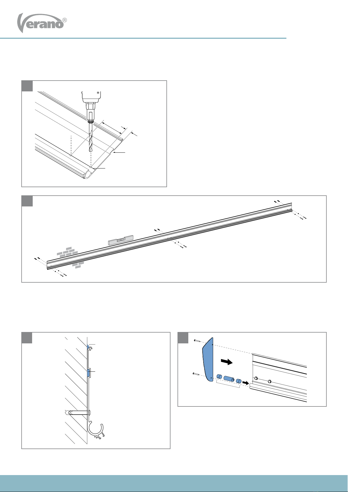
• Drill 2 holes into the wall prole at the height of every
beam. Drill on the drill line. Use a metal drill Ø 8 mm.
• Place the compri tape in the recess of the wall prole.
1. Installationofthewallprole
Compriband
KitrandMuur
46 mm
65 mm
3x
1
2
3 4
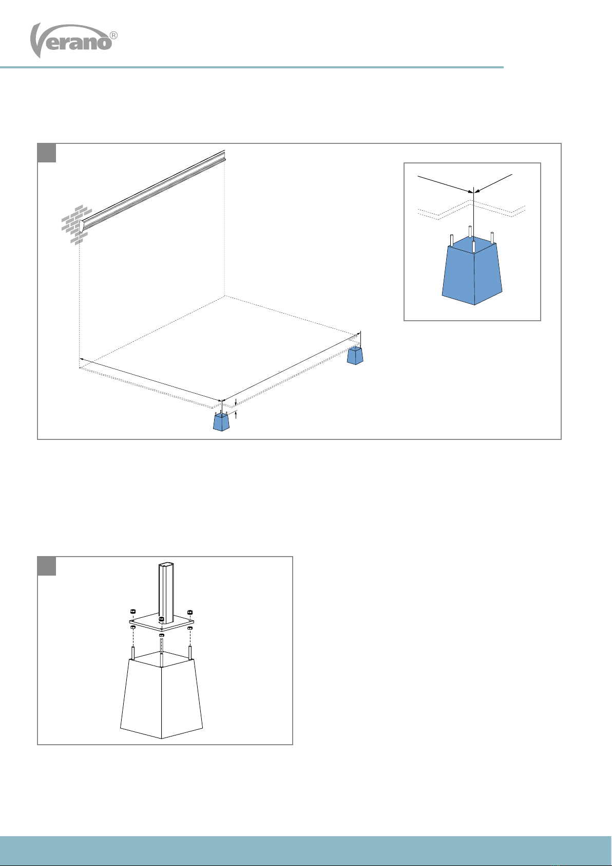
• Mark a line on the wall that indicates the location of the lower side of the wall prole. Place the wall prole on the line
and mark the holes as they are pre-drilled in the wall prole.
• Drill the holes with a concrete drill 8 mm. Make sure that the wall prole is level.
• Install the wall prole. Screws, plugs and rings are not included in the delivery. Use at least a 8 mm plug and M8 screw
to install the wall prole completely.
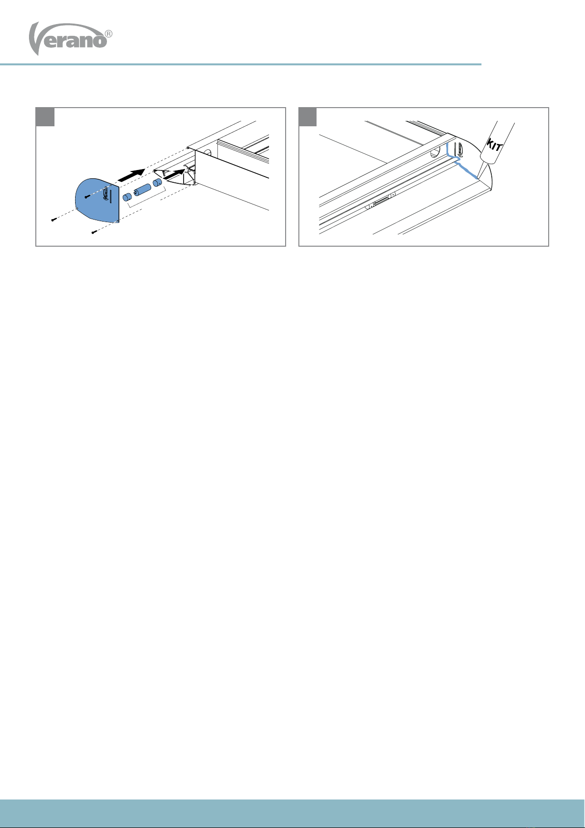
• Seal the complete edge of the wall prole at the top.
• Slide the beam connections, three pieces per beam, into
the wall prole.
• Install the end cap to the wall prole. Only do this at the
engine side!
Boorlijn
C
ompriband
80 mm
20 mm
Compri tape
Compri tape
Wall Seal
Drill line

1779-160404(2)Drukfouten, fouten en technische wijzigingen voorbehouden.
INSTALLATION MANUAL VERANDA V950 - LUGANO
10361814-191125EN
4
Subject to misprints, errors and technical modifications.
• Slide the three gutter proles into each other.
• Install the screwable drainage and the leaf catcher to
both the drainage holes in the gutter.
• For a perfect sealing, seal the lower side of the drainage
before you place it into the hole.
2. Preparing the gutter
5
6
6a
46 mm
65 mm
3x

1779-160404(2)Drukfouten, fouten en technische wijzigingen voorbehouden.
INSTALLATION MANUAL VERANDA V950 - LUGANO
10361814-191125EN
5
Subject to misprints, errors and technical modifications.
3. Preparing the uprights
• Saw the uprights custom.
Attention! Don’t saw the side where the pre-drilled hole
for the connection piece is located.
• Drill a 13 mm hole 300 mm from the lower side. This hole
is drilled for the xation of the foot plate later on.
The uprights are standardly 250 cm long and need to be customized by you. The size of the uprights is 10 cm longer than
size H2. You have noted size H2 on your order form. H2 is the size measured from the surface/terrace up to the lower side of
the gutter prole. The extra 10 cm is the size from the terrace up to the top side of the concrete base.
Bestelmaat H2 plus 10 cm
10 cm
Maat D plus 20 mm
Maat B plus 35 mm
7 8
300 mm
10 cm
Order height H2 plus 10 cm

1779-160404(2)Drukfouten, fouten en technische wijzigingen voorbehouden.
INSTALLATION MANUAL VERANDA V950 - LUGANO
10361814-191125EN
6
Subject to misprints, errors and technical modifications.
4. Connection of the uprights
9
9c
9a
9d
• Slide the upright over the connection piece all the way up
to the gutter.
Attention! The side of upright perfectly connects to the side of the gutter.
• Fixate the upright to the connection piece using two
screws.
• Slide the connection block into the lower side of the
gutter.
• Fixate the connection block 3 mm from the edge with two
hexagon screws.
• Install the connection piece to the connection block with
two screws.
3 mm
3 mm
3 mm
3 mm
9b

1779-160404(2)Drukfouten, fouten en technische wijzigingen voorbehouden.
INSTALLATION MANUAL VERANDA V950 - LUGANO
10361814-191125EN
7
Subject to misprints, errors and technical modifications.
11
• Slide the beam connections, three pieces per beam, into
the gutter.
• Install the end cap to the gutter on both sides.
• Seal the inside of the end cap.
3x
10

1779-160404(2)Drukfouten, fouten en technische wijzigingen voorbehouden.
INSTALLATION MANUAL VERANDA V950 - LUGANO
10361814-191125EN
8
Subject to misprints, errors and technical modifications.
12
• Place the concrete bases as precisely as possible into the ground at the right position below the gutter. Make sure that
the top of the concrete bases are placed at least 10 cm below the terrace level.
Make sure that they are levelled.
• The distance between the foundation blocks and the wall is size D plus 20 mm.
• You already noted size D on your order form.
• The distance between the uprights is size B plus two times 17,5 mm.
5. Placing the foundation
13
• Install the foot plates to the concrete bases.
10 cm
Maat D plus 20 mm
Maat B plus 35 mm
10 cm
Maat D plus 20 mm
Maat B plus 35 mm
Size D plus 20 mm
Size B plus 35 mm

1779-160404(2)Drukfouten, fouten en technische wijzigingen voorbehouden.
INSTALLATION MANUAL VERANDA V950 - LUGANO
10361814-191125EN
9
Subject to misprints, errors and technical modifications.
6. Placing the uprights and the gutter
14 15
16
• Straighten the uprights with the gutter. • Place the uprights over the installation feet and xate
levelled. The foundation blocks have welded threated
ends with each two nuts, thus the uprights can be
adjusted in height.
Attention! Make sure that the concrete bases are stable
and xated into the ground. The uprights now need to sup-
port the gutter. Possible struts can be removed.
• Screw the upright to the installation foot.

1779-160404(2)Drukfouten, fouten en technische wijzigingen voorbehouden.
INSTALLATION MANUAL VERANDA V950 - LUGANO
10361814-191125EN
10
Subject to misprints, errors and technical modifications.
• Place the rst beam on the side of the engine (where the end caps are installed).
• Slide the beam connection below the beam to its place. Do this at the wall prole and the gutter.
• Slide the connection pieces and the beam tightly to the
end cap.
• Screw the connection pieces on the le- and right side to
secure the beam.
• Do this at the wall prole and the gutter.
Place the second and third beam the same way.
7. Placing the beams
17
17a
18 19
1e
2e
3e
17b
1
1
2
1
1
2

1779-160404(2)Drukfouten, fouten en technische wijzigingen voorbehouden.
INSTALLATION MANUAL VERANDA V950 - LUGANO
10361814-191125EN
11
Subject to misprints, errors and technical modifications.
8. Placingthedriveshas
20
21 22
• Attention!Beforeyouplacethetube,checkiftherstcarriagesinthebeamsareinfrontpositiontothe
bolt in the gutter!
• Place the tube against the side beam.
The position of the engine depends on the choice you made with your order. The engine can be positioned le, right or
in the middle. Make sure that, when placing the tube, the sprocket is located at the side of the beam where the engine is
installed. In this manual, the engine is positioned on the le side of the center beam.
• Slide the center beam tightly against it. • Screw the connection pieces on the le- and right side to
secure the center beam.
1e wagentje
1e wagentje
1e wagentje
First carriage
First carriage
First carriage
First carriage

1779-160404(2)Drukfouten, fouten en technische wijzigingen voorbehouden.
INSTALLATION MANUAL VERANDA V950 - LUGANO
10361814-191125EN
12
Subject to misprints, errors and technical modifications.
23
24
26 27
25
• Place the drive sha to the center beam. To make space,
slide the side beam and the connection piece to the side.
Notethepositionoftherstcarriagesinthebeams!
• Install the second end cap to the wall prole. • Slide the side beam and the connection pieces tightly to
the end cap (also see gure 18).
• Screw the connection pieces to the le- and right side to
secure the beam (see gure 19).
• Slide the side beam and the outermost connection piece
against it.

1779-160404(2)Drukfouten, fouten en technische wijzigingen voorbehouden.
INSTALLATION MANUAL VERANDA V950 - LUGANO
10361814-191125EN
13
Subject to misprints, errors and technical modifications.
9. Position and alignment
90°
90°
90°
90°
28
29
• Measure diagonally and check if the sizes are the same.

1779-160404(2)Drukfouten, fouten en technische wijzigingen voorbehouden.
INSTALLATION MANUAL VERANDA V950 - LUGANO
10361814-191125EN
14
Subject to misprints, errors and technical modifications.
10. Placing the roof panels
30
3231
• Install the corner proles. • Install the second and other roof plates the same way.
• Place the rst roof plate and screw it to the beams.
30a
boorlijn
Drill line

1779-160404(2)Drukfouten, fouten en technische wijzigingen voorbehouden.
INSTALLATION MANUAL VERANDA V950 - LUGANO
10361814-191125EN
15
Subject to misprints, errors and technical modifications.
11. Placing the engine
‘klik’
33
34
• Place the engine unit. Click the tube on the support of the engine plate. The sprockets now stack inside each other.
• Screw the engine unit from the lower side to the roof
plate in the pre-drilled installation holes. (The position
of the screw hole can variate regarding the drawing.)
‘klik’
‘klik’
‘Click’
35
• Screw the corner prole to the bottomside of the third
roof plate in the pre-drilled installation holes.

1779-160404(2)Drukfouten, fouten en technische wijzigingen voorbehouden.
INSTALLATION MANUAL VERANDA V950 - LUGANO
10361814-191125EN
16
Subject to misprints, errors and technical modifications.
‘Klik’
‘Klik’
12. Placing the fabric with ribs
36
37 38
• Unroll the fabric with the ribs. Fabric side above.
• Remove the cover plates from the ribs.
• Position the rst rib, which is located on the wall side, on the lower side to the beams.
• Hook, by using the included chain, the carriage to the eye.
• Install the rst rib. Position the carriage above the rib
and install the rib with the hexagon bolt in the hole of
the carriage.
• Install the second rib the same way and work forward.
• Click all the cover plates back into the ribs.
1e
2e
3e
‘Klik’
‘Klik’
‘Click’

1779-160404(2)Drukfouten, fouten en technische wijzigingen voorbehouden.
INSTALLATION MANUAL VERANDA V950 - LUGANO
10361814-191125EN
17
Subject to misprints, errors and technical modifications.
Muur
‘Klik’
39
• Click the piping at the end of the fabric in the lower side
of the wall prole.
‘Click’
Wall

1779-160404(2)Drukfouten, fouten en technische wijzigingen voorbehouden.
INSTALLATION MANUAL VERANDA V950 - LUGANO
10361814-191125EN
18
Subject to misprints, errors and technical modifications.
13. Placing the drainage
14. Uprightnish
40 For each pipe, two clamp supports Ø 50 are needed.
• Drill 3 mm holes in the middle of the upright and screw the clamps to the
back side of the upright.
Attention!
If the veranda is placed between two walls and the overows can not
function anymore, the drainage needs to be adjusted with an extra
drainage. This way water overow can be prevented.
• Click the cover plate on both uprights.
41
Table of contents
Popular Tent manuals by other brands

ClearSpan
ClearSpan 106777 manual

Home & Leisure
Home & Leisure Trex Wall Pergola installation instructions

Eureka
Eureka Zeus Classic Assembly instructions

Ballard Designs
Ballard Designs JU017 Assembly instructions

skandika outdoor
skandika outdoor GOTLAND 5 Setup Instruction

23zero
23zero DUKE ANNEX Setup manual