Shandong Renke Control Technology RS-YG-N01 User manual

Photoelectric Smoke Fire Alarm User ManualV2.0
Shandong Renke Control Technology Co., Ltd. www.renkeer.com
1
RS-YG-N01
485 type photoelectric smoke
detector fire alarm
User manual
Document version:V2.0

Photoelectric Smoke Fire Alarm User ManualV2.0
Shandong Renke Control Technology Co., Ltd. www.renkeer.com
2
Table of Contents
1. Product introduction........................................................................................................................3
1.1product description.................................................................................................................3
1.2 Main Specifications...............................................................................................................3
1.3 System framework................................................................................................................ 3
2. product features....................................................................................................................... 3
3. Dimensions......................................................................................................................................4
4. Installation and wiring instructions.................................................................................................4
4.1 Equipment inspection before installation............................................................................. 4
4.2 Wiring instructions................................................................................................................ 4
4.3 Installation Notes.................................................................................................................. 5
4.3.1 Suitable installation location......................................................................................5
4.3.2 Suitable installation location......................................................................................5
4.3.3 installation method.....................................................................................................5
5. Configuration software installation and use.................................................错误!未定义书签。
5.1 Software selection................................................................................................................. 6
5.2 parameter settings..................................................................................................................7
6. letter of agreement...........................................................................................................................8
6.1 Basic communication parameters......................................................................................... 8
6.2 Data frame format definition.................................................................................................9
6.3 Register address.................................................................................................................. 10
6.4 Communication protocol example and explanation........................................................... 10
7. Common problems and solutions..................................................................................................11
8. Contact information.......................................................................................................................11
9. Document history..........................................................................................错误!未定义书签。

Photoelectric Smoke Fire Alarm User ManualV2.0
Shandong Renke Control Technology Co., Ltd. www.renkeer.com
3
1.Product introduction
1.1 product description
The RS-YG-N01 Photoelectric Smoke Fire Alarm (hereafter referred to as the alarm) is
capable of detecting smoke generated during a fire. The alarm adopts photo-electricity smoke
device and excellent production technology. It has stable work, beautiful appearance, simple
installation and no need for debugging. It can be widely used in shopping malls, hotels, shops,
warehouses, computer rooms, houses and other places for fire safety testing. The alarm has a
built-in buzzer that emits a strong sound after an alarm. The alarm uses standard 485 signal output,
Modbus protocol, and supports secondary development.
1.2 Main Specifications
Power supply:10~30V DC Static power:0.12W
Alarm power consumption:0.7W Alarm sound:≥80dB
Signal output:RS485 letter of agreement:Modbus-RTU
Smoke sensitivity:1.06±.26%FT Standards compliant:GB4715-2005
working environment:-10℃~50℃,≤95%,No condensation
1.3 System framework
System solution block diagram
2. product features
1.Ceiling installation
2.Tamper cover
3.Using a microprocessor
Device1
number
Device2
2number
Device3
33number
Device n
485 bus
USB to 485 or 232 to 485
10~30V DC
UPS power supply
(optional)
AC220V Mains
Monitoring computer
Photoelectric Smoke Fire Alarm User ManualV2.0
Shandong Renke Control Technology Co., Ltd. www.renkeer.com
4
4. Automatic temperature compensation
5. Full 360°detection
6. LED ON&OFF selectable
7. Adjustable alarm delay
8. Using patch technology, anti-EMI, RFI interference
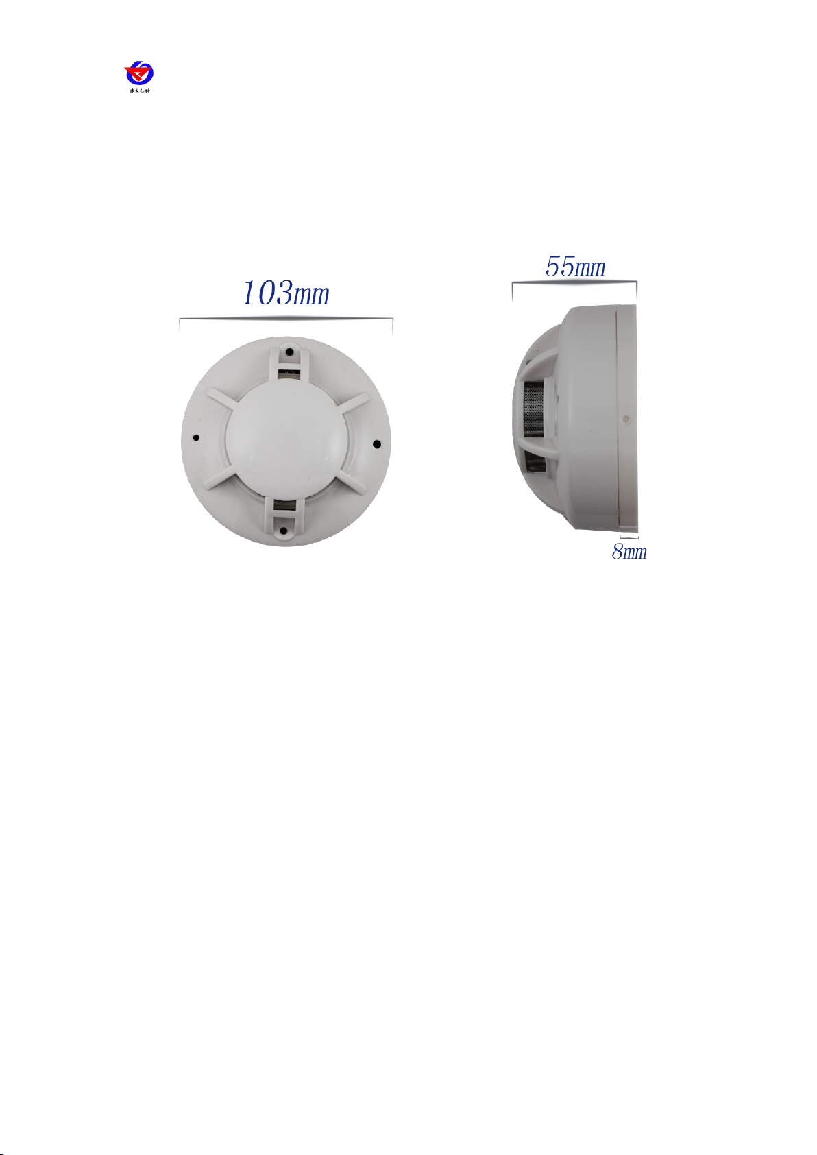
3. Dimensions
4. Installation and wiring instructions
4.1 Equipment inspection before installation
Equipment List:
1. 1 set of smoke sensor
2. Certificate, warranty card, wiring instructions, etc.
3. 12V/1A waterproof power supply 1 (optional)
4. USB to 485 (optional)
4.2 Wiring instructions
The power input can be 10~30V. When wiring the 485 signal line, note that the A\B lines
cannot be connected in reverse, and the addresses between multiple devices on the bus cannot
conflict.

Photoelectric Smoke Fire Alarm User ManualV2.0
Shandong Renke Control Technology Co., Ltd. www.renkeer.com
5
Line color
Description
Remarks
brown
Power supply
10~30V DC
black
Negative power supply
yellow
485-A
blue
485-B
4.3Installation Notes
4.3.1Suitable installation location
When installed on the roof, it should be placed in the middle of the roof. If it is installed on the
inclined or human roof, the alarm should be kept at a certain distance from the roof. When the
slope is less than 30°, the distance is 0.2m, more than 30°. The distance is from 0.3m to 0.5m.
4.3.2 Location and environment to avoid installation
1. Places where smoke is normally trapped
2. Locations with large dust, water mist, steam, oil mist pollution and corrosive gases
3. Locations with relative humidity greater than 95%
4. Locations with ventilation speeds greater than 5 m/s
5. Close to fluorescent fixtures
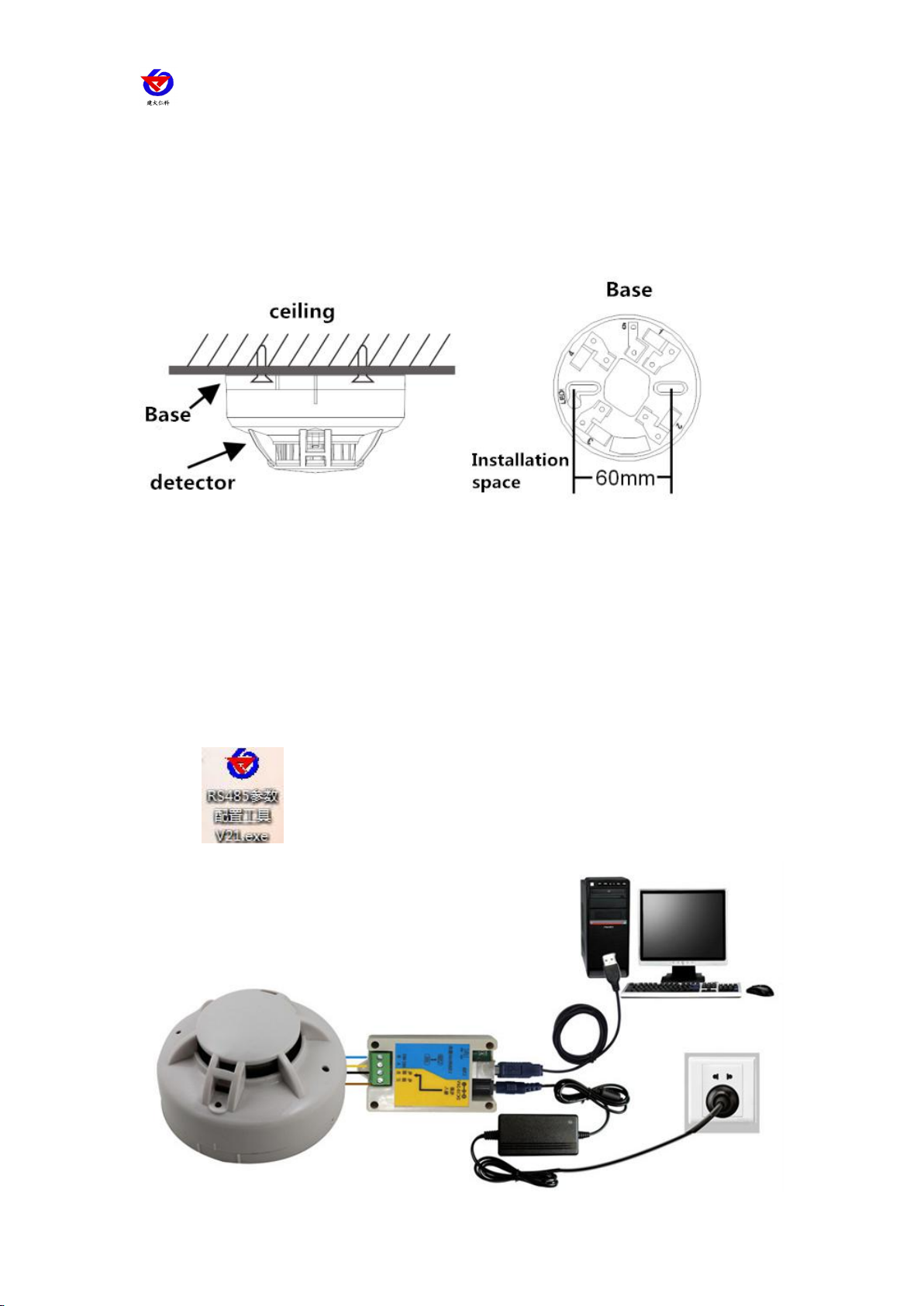
4.3.3 installation method
Two mounting holes of 5 mm in diameter were placed at a distance of 60 mm from the ceiling,
and the detector base was fixed to the ceiling with a plug and a screw.
Photoelectric Smoke Fire Alarm User ManualV2.0
Shandong Renke Control Technology Co., Ltd. www.renkeer.com
6
5. Configuration software installation and use
5.1 Software selection
Open the package and select "Debug Software"---"485 Parameter Configuration Software" to
find Open it.

Photoelectric Smoke Fire Alarm User ManualV2.0
Shandong Renke Control Technology Co., Ltd. www.renkeer.com
7
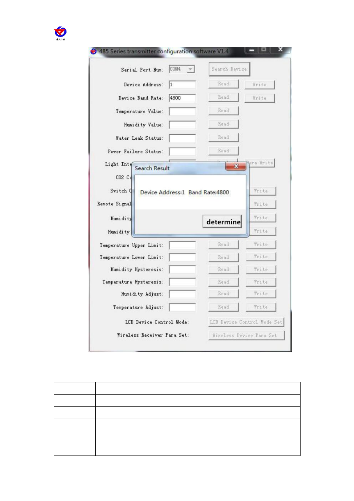
5.2parameter settings
1. Select the correct COM port ("My Computer - Properties - Device Manager - Port"
to view the COM port). The following figure lists the drive names of several different
485 converters.
2. Connect only one device and power on separately. Click the test baud rate of the
software. The software will test the baud rate and address of the current device. The
default baud rate is 4800 bit/s and the default address is 0x01.
3. Modify the address and baud rate according to the needs of use, and query the
current functional status of the device.
4. If the test is not successful, please re-check the equipment wiring and 485 driver
installation
Photoelectric Smoke Fire Alarm User ManualV2.0
Shandong Renke Control Technology Co., Ltd. www.renkeer.com
8
5.
6. letter of agreement
6.1 Basic communication parameters
Code
8-bit binary
Data bit
8 digits
Parity bit
no
Stop bit
1 person
Error check
CRC (redundant cyclic code)
Baud rate
2400bit/s, 4800bit/s, 9600 bit/s can be set, the factory default is 4800bit/

Photoelectric Smoke Fire Alarm User ManualV2.0
Shandong Renke Control Technology Co., Ltd. www.renkeer.com
9
s
6.2 Data frame format definition
Adopt Modbus-RTU communication protocol, the format is as follows:
Initial structure ≥ 4 bytes of time
Address code = 1 byte
Function code = 1 byte
Data area = N bytes
Error check = 16-bit CRC code
End structure ≥ 4 bytes of time
Address code: is the address of the transmitter, which is unique in the communication network (factory default 0x01).
Function code: The instruction function of the command sent by the host. This transmitter only uses function code 0x03
(read register data).
Data area: The data area is the specific communication data. Note that the 16-bit data high byte is in front!
CRC code: Two-byte check code.

Photoelectric Smoke Fire Alarm User ManualV2.0
Shandong Renke Control Technology Co., Ltd. www.renkeer.com
10
Host inquiry frame structure:
address
code
function
code
Register start
address
Register
length
Check code low
Check code high
1 byte
1 byte
2 bytes
2 bytes
1 byte
1 byte
Slave response frame structure:
address
code
function
code
Effective
number of
bytes
Data area
Second data
area
Nth data area
Check code
1 byte
1 byte
1 byte
2 bytes
2 bytes
2 bytes
2 bytes
6.3 Register address
Register address
PLC or configuration
address
content
operating
0003 H
40004
Alarm status
Read only
6.4 Communication protocol example and explanation
Example: Asking for the working status of the alarm
Inquiry frame:
address code
function code
starting addres
s
Data length
Check code l
ow
Check code hi
gh
0x01
0x03
0x00 0x03
0x00 0x01
0x74
0x0A
Response frame: Answer to the alarm status alarm
address code
function code
Returns the nu
mber of valid b
ytes
Alarm status
Check code l
ow
Check code
high
0x01
0x03
0x02
0x00 0x01
0x79
0x84
Alarm status description:
Alarm status code
Alarm status
0
normal
1
Call the police

Photoelectric Smoke Fire Alarm User ManualV2.0
Shandong Renke Control Technology Co., Ltd. www.renkeer.com
11
7. Common problems and solutions
The device cannot be connected to the PLC or computer, possible reasons:
1) The computer has multiple COM ports, and the selected port is incorrect.
2) The device address is incorrect, or there is a device with a duplicate address (all the factory
defaults to 1).
3) Baud rate, check mode, data bit, stop bit error.
4) The host polling interval and the waiting response time are too short and need to be set to more
than 200ms.
5) The 485 bus is disconnected, or the A and B lines are reversed.
6) If the number of devices is too large or the wiring is too long, the power should be supplied
nearby, add 485 enhancer, and increase the resistance of 120Ω terminal.
7) The USB to 485 driver is not installed or damaged.
8) Equipment damage.
8. Contact information
Shandong Renke Measurement & Control Technology Co., Ltd.
Address: 2886 Fengjing Road, High-tech Zone, Jinan City, Shandong Province
Zip code: 250101
Phone: 400-085-5807
Fax: (86)0531-67805165
Website: www.renkeer.com
Cloud platform address: www.0531yun.cn
9. Document history

Photoelectric Smoke Fire Alarm User ManualV2.0
Shandong Renke Control Technology Co., Ltd. www.renkeer.com
12
The V1.0 documentation was created.
V2.0 documentation update.
Table of contents


