PSA LIF5800/2 User manual

MODEL LIF5800/2 & LIF5800RL/2
LIFESAVER SMOKE ALARM
INSTALLATION AND USER MANUAL
IMPORTANT: READ ALL INSTRUCTIONS BEFORE INSTALLATION.
NO USER REPLACEABLE PARTS INSIDE THIS SMOKE ALARM.
WARNING: Disconnecting smoke alarm from mounting base and/or removing the 9V battery
will render this smoke alarm inactive.
240VAC Mains Powered Photoelectric Smoke Alarm. Single station
operation or inter-connectable up to 24 units.
Model LIF5800/2: 240VAC 9VDC battery backup.
Model LIF5800RL/2: 240VAC rechargeable lithium battery backup.
SPECIFICATION
ELECTRICAL RATING: 240VAC 50Hz, 10mA per alarm and interconnectable to
24 alarms.
WARNING: THIS SMOKE ALARM MUST ONLY BE WIRED TO A
240Vac 50Hz SINE WAVE CURRENT SUPPLY.
THIS PHOTOELECTRIC SMOKE ALARM CONTAINS NO RADIOACTIVE
MATERIALS
1398-7211-01_B2_V2:_ 2017.9.7 3:55 PM Page 1

RECOMMENDED LOCATIONS OF ALARMS ................................................................................1
AVOID THESE LOCATIONS............................................................................................................................. 3
FALSE ALARMS.............................................................................................................................................................3
HOW TO REMOVE SMOKE ALARM FROM BASE PLATE..............................................4
INSTALLATION...............................................................................................................................................................4
OPERATION, TESTING AND MAINTENANCE..........................................................................10
BATTERY INSTALLATION, REPLACEMENT AND TEST..............................................12
MAINTENANCE..........................................................................................................................................................14
9V TERMINAL...............................................................................................................................................................15
REPAIRS AND SERVICES..................................................................................................................................17
GOOD SAFETY HABITS.....................................................................................................................................17
THE LIMITATIONS OF SMOKE ALARMS.......................................................................................17
OPERATING PRINCIPLES OF SMOKE ALARMS....................................................................19
DEVELOP AND PRACTICE A PLAN OF ESCAPE...................................................................20
WHAT TO DO WHEN THE ALARM SOUNDS.............................................................................21
INSTALLER PLEASE NOTE...........................................................................................................................22
WARNING: INSULATION TEST.................................................................................................................22
WARRANTY AND LIABILITY.....................................................................................................................23
CONTENTS
1398-7211-01_B2_V2:_ 2017.9.7 3:55 PM Page 2

1
1. RECOMMENDED LOCATIONS OF ALARMS
1.1 Check specific State legislation in your area to ensure smoke alarms are
correctly located according to local laws. Each State or Territory may differ
in building codes and regulations. PSA Products can only recommend the
locations.
1.2 Locate an alarm for each separate sleeping area in the immediate vicinity of
the bedrooms. Try to monitor the exit path as the bedrooms are usually
farthest from an exit. If more than one sleeping area exit, locate additional
alarms in each sleeping area in the immediate vicinity bedrooms.
1.3 Locate additional alarms to MONITOR any stairway as stairways act like
chimneys for smoke and heat.
1.4 Locate at least one alarm on every floor level.
1.5 Locate an alarm in every room where a smoker sleeps.
1.6 Locate an alarm in every room where electrical appliances are operated (i.e.
portable heaters or humidifiers).
1.7 Locate an alarm in every room where someone sleeps with the door closed.
The closed door may prevent an alarm not located in that room from waking
the sleeper.
1.8 Smoke, heat and other combustion products rise to the ceiling and spread
horizontally. Mounting the alarm on the ceiling in the center of the room
places it closest to all points in the room. Ceiling mounting is preferred in
ordinary residential construction.
1.9 When mounting alarms on the ceiling locate it at least 300mm away from the
side wall and 300mm away from any corner. (see diagram)
1.10 When mounting alarms on a wall, use the inside wall. The recommended
position is between 300mm and 500mm off the ceiling. (see diagram)
NOTE: The performance of smoke alarms mounted on walls is unpredictable
and this mounting position is not recommended when ceiling mounting can be
implemented.
1398-7211-01_B2_V2:_ 2017.9.7 3:55 PM Page 1

2
1.10 When mounting the alarm at the apex of a sloping ceiling it should be
located at least 500mm away from the apex but should not exceed
1500mm (see diagram).
1.11 Locate smoke alarm at both ends of a bedroom hallway or large room
if the hallway or room is more than 9m long.
1.12 Do not locate smoke alarms in kitchen areas due to potential nuisance
alarms from cooking fumes.
1. RECOMMENDED LOCATIONS OF ALARMS
INSTALLATION OF SMOKE ALARM
IMPORTANT: INCORRECT ORIENTATION OF SMOKE ALARM MAY DECREASE
OPERATIONAL EFFECTIVENESS
1398-7211-01_B2_V2:_ 2017.9.7 3:55 PM Page 2

3
3. FALSE ALARMS
3.1 This smoke alarm is designed to minimize false alarms. Smoking will not
normally set off the alarm unless smoke is blown directly into the alarm.
3.2 Combustion particles from cooking may set off the alarm if the alarm is
located close to the kitchen cooking surface.
3.3 Large quantities of combustion particles are generated from spills and over-boil.
3.4 An alarm with a Hush® Control device is preferable near a kitchen
environment for this reason.
3.5 If the alarm does sound, check for fire first. If a fire is discovered, escape quickly
and call the Fire Brigade. If no fire is present, check to see if one of the reasons
listed above may have caused the alarm.
2. AVOID THESE LOCATIONS
2.1 Do not locate your alarm in the garage - products of combustion are present
when you start your automobile. Use Lifesaver Heat Alarm in this location.
2.2 Do not locate your alarm in front of forced air supply ducts used for heating and
air conditioning and other high air flow areas.
2.3 Do not locate your alarm less than 500mm from the peak of an "A" frame type
ceiling.
2.4 Do not locate your alarm in areas where temperatures may fall below 0°C or rise
above 40°C, or in humidity higher than 93% as these conditions may
reduce battery life.
2.5 Avoid dusty areas, dust particles may cause smoke alarm to false alarm or fail to
alarm. Use Lifesaver Heat Alarm in this location to avoid false alarms.
2.6 Avoid very humid areas or near a bathroom, moisture can cause false alarm.
2.7 Avoid insect-infested areas.
2.8 Do not locate alarm within 0.9m of the following: the door to a kitchen, the door
to a bathroom containing a tub or shower, ceiling or whole house ventilat-
ing fans, or other high flow areas.
2.9 Avoid locating near fluorescent lights or other electrical equipment. Electronic mag-
netic interferences or “noise” may cause nuisance alarms or chirping.
2.10 Smoke alarms are not to be used with detector guards unless the combination
(alarm and guard) has been evaluated and found suitable for that purpose.
1398-7211-01_B2_V2:_ 2017.9.7 3:55 PM Page 3
4
L
I
F
5
8
0
0
R
L
/
2
TEST
HUSH
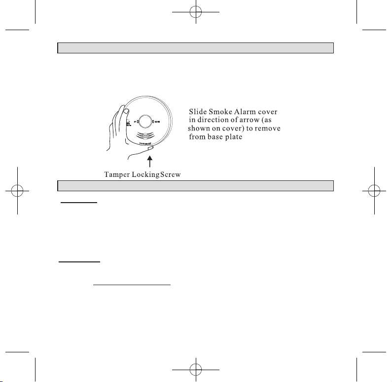
4. HOW TO REMOVE SMOKE ALARM FROM BASE PLATE
4.1 Look for ‘SLIDE TO REMOVE’.
4.2 Remove Tamper Locking Screw if installed.
4.3 Push firmly towards arrow until smoke alarm unhinges from base plate.
4.4 To re-install smoke alarm follow FIGURE 2 procedure 1 to 3. See page 9.
5. INSTALLATION
DANGER: ELECTRICAL SHOCK HAZARD. Turn off power at the main
fuse box or circuit breaker by removing the fuse or switching the
circuit breaker to the OFF position and securing it. An all-pole
mains switch with a contact separation of at least 3mm in each
pole shall be incorporated in the electrical installation of the
building.
WARNING: THIS SMOKE ALARM MUST BE INSTALLED BY
QUALIFIED (LICENSED) ELECTRICIANS ONLY.
5.1 Wiring Instructions:
5.1.1 In the interests of safety, this smoke alarm and all wiring must be installed by
a licensed electrician in accordance with the relevant requirements of the
AS/NZS Wiring Rules - AS3000.
1398-7211-01_B2_V2:_ 2017.9.7 3:55 PM Page 4

5
5.1.2 For model LIF5800RL/2; Connecting the smoke alarm on the base plate will
activate the lithium battery. Please note, the long absence of mains power may
damage the rechargeable battery. Warranty is void if the battery is
damaged. If the mains power is turned off for a long period of time, for
example, if the building is not occupied, disconnect the smoke alarm from the
base plate. When mains power is turned on, ensure the smoke alarm is then
connected to the base plate. The battery may be low in new smoke alarms,
please allow up to 8 hours for the battery to fully charge. Smoke alarms may
chirp until the battery is fully charged. When recharging do not press
Test/Hush button.
5.1.3 This Smoke Alarm can only interconnect with PSA Products LIFESAVER
range of smoke alarms, heat alarm and accessories. Interconnection with other
brands may cause damage or result in a shock or fire risk and void warranty.
5.1.4 Due to “noise” from electromagnetic interference, up to 24 units of smoke
alarms and compatible products may be interconnected.
5.1.5 There are five terminals in the supply terminal block, marked 9V, A, SW, N,
LOOP. It is important that the alarm be wired correctly to ensure correct
operation. Incorrect wiring to the Smoke Alarm will damage the unit and void
the warranty.
5.1.6 A total maximum of 250 meters (820 feet) of wire can be used in interconnect-
ing smoke alarms.
5.1.7 All final sub-circuit conductors including the signal conductor must be a
minimum size of 1mm² with 250V grade insulation.
5.1.8 Interconnected Smoke Alarms must be connected to the same final subcircuit.
5.1.9 Do not use any wire that could later be confused with the normal house wires
for the interconnect wire. For example, green/yellow earth wire.
5.1.10 Do not connect AC power wires to SW interconnect terminal. These will
damage smoke alarms.
5.1.11 Do not connect the SW interconnect wire to any device, except the SW
interconnect terminal of smoke alarm. Otherwise, smoke alarm will be
damage.
5.1.12 Switch wire (SW) only can drive the RK10A/9 and smoke alarms.
5.1.13 Do not connect 9V wire to AC power or SW interconnect terminal.
This will damage the smoke alarms.
5. INSTALLATION
1398-7211-01_B2_V2:_ 2017.9.7 3:55 PM Page 5

6
5.1.14 Smoke alarms should be interconnected only within the confines of a single
family living unit. If smoke alarms are interconnected between different
units, there may be excessive nuisance alarms. Residents may not be aware
that smoke alarms are being tested or that it is a nuisance alarm caused by
cooking, etc.
5.1.15 Terminals at back of mounting base are marked and coloured as follows:
MARKINGS
(Yellow) 9V 9Vdc POSITIVE POWER SOURCE
(Red) A ACTIVE
(White) SW SWITCH WIRE (FOR INTERCONNECTION ONLY)
(Blue) N NEUTRAL
(Orange) LOOP DEAD TERMINAL
WARNING: Connecting the Switch wire terminal to any other supply conduc-
tor may result in damage to the alarm, failure to operate or shock hazard and
void the warranty of the alarm.
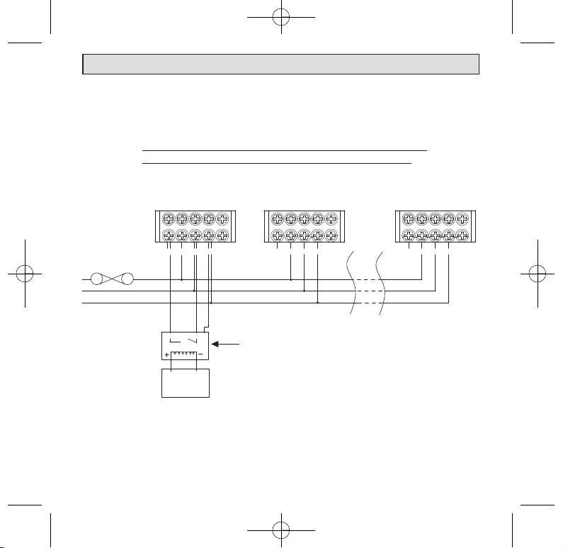
EXAMPLE OF MULTIPLE ALARM WIRING / ISOLATION UNIT WIRING
5. INSTALLATION
LOOP
1
N
9V SW
A
LOOP
2
SW
9V AN
BLUE
ORANGE
ORANGE
YELLOW
WHITE
RED
YELLOW
BLUE
WHITE
RED
24
9V ASW N
LOOP
MAXIMUM OF 24 SMOKE ALMARMS
CONNECTION TO A
SW N
FUSE ON
CIRCUIT
BREAKER
SEE INSTALLATION INSTRUCTIONS
FOR LIFSAVER RK10A/9 RELAY MODULE
TO ALARM PANEL
OR
AUXILIARY DEVICES
1398-7211-01_B2_V2:_ 2017.9.7 3:55 PM Page 6

7
Note: For interconnection of smoke alarms to Fire Panel or Auxiliary
devices, use only LIFESAVER Isolation Relay Model RK10A/9.
5.1.16 This Smoke Alarm can be interconnectable only with other LIFESAVER
models of Smoke Alarms; whether it be of Ionisation or Photoelectric design.
Interconnection with other brands may cause damage or result in a shock or
fire risk.
5.1.17 When interconnected all Smoke Alarms will sound upon activation.
5.1.18 WARNING: This alarm cannot be operated from power derived from a
square wave, modified square wave or modified sine wave inverter. These
type of inverters are sometimes used to supply power to the structure in
off grid installations, such as solar or wind derived power sources. These
power sources produce high peak voltages that will damage the alarm.
5.1.19 PSA recommend the smoke alarms to be installed on its own subcircuit to
avoid false alarms and nuisance chirping that may be caused by electromag-
netic interferences from other electrical equipment.
5.1.20 Do not install smoke alarm in the same subcircuit as electrical equipment
likely to produce electrical noise and interference to the mains supply. Eg. air-
conditioners, fans, heat lamps, and lighting dimmers.
5.2 Mounting Instructions:
5.2.1 Separate Smoke Alarm from mounting base by sliding cover (in direction of
arrow) with one hand on the back of the mounting base and one hand sliding
Smoke Alarm(See Fig. 1).
5.2.2 Connect supply cable to terminal block and fix terminal cover.
5.2.3 Align and slide smoke alarm up onto mounting base (Fig. 2) then slide in the
reverse direction of arrow to ensure proper connection.
5.2.4 Switch on power and check the green light on alarm cover. It should be lit
when mains power is switched on indicating that the smoke alarm is properly
connected to the mounting base.
5.2.5 Secure Tamper Locking Pin (supplied) to smoke alarm.
5.2.6 Test alarm by pressing Test button.
5. INSTALLATION
1398-7211-01_B2_V2:_ 2017.9.7 3:55 PM Page 7
8
5. INSTALLATION
L
I
F
5
8
0
0
R
L
/
2
TEST
HUSH
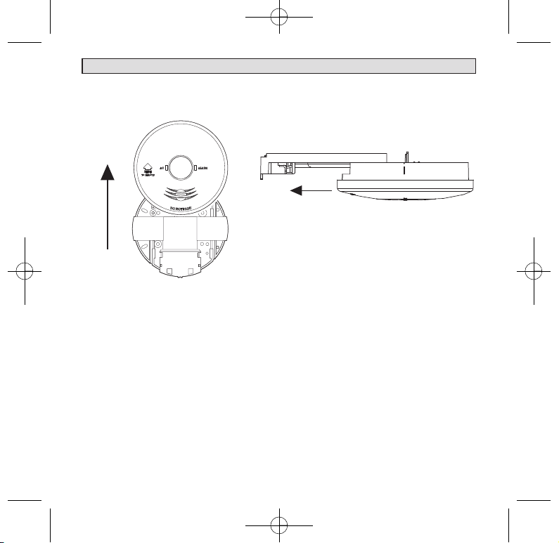
Figure 1:To remove smoke alarm
Slide smoke alarm carefully
away from the base plate to
remove the smoke alarm.
Figure 2: To connect smoke alarm
1 Place smoke alarm in line with the
base plate.
2 Push smoke alarm towards
connector (A). Ensure the smoke
alarm slides fully into the
connector.
3 Green AC Power light will come
on when connected to mains.
A
1398-7211-01_B2_V2:_ 2017.9.7 3:55 PM Page 8
9
L
I
F
5
8
0
0
R
L
/
2
TEST
HUSH
6. OPERATION, TESTING AND MAINTENANCE
6.1 Operation:
6.1.1 The smoke alarm is operational once all wires are properly connected, a fresh
battery is installed and the battery activate tab is pulled out (LIF5800/2),
The smoke alarm is correctly installed on the mounting base and the alarm
has been tested.
6.1.2 Pressing and holding the TEST button will sound the alarm and test the elec-
trical function of the smoke alarm. Releasing the TEST button will stop the
alarm and the smoke alarm automatically enters hush mode. See 6.2.
6.1.3 Red LED
6.1.3.A Stand-by condition: will flash once approximately every 5 minutes to
indicate unit is functioning properly.
6.1.3.B The red LED will flash when unit goes into alarm, indicating that
products of combustion have been detected. The flashing Red LED and
three beeps (loud 85dBA at 3m) will continue until the air is cleared. For
interconnected units, the originating smoke alarm Red LED will flash
every 1 second. All other units will sound but the Red LED will not flash.
6.1.4 Green LED
6.1.4.A AC Mains-ON Indicator: indicates that the unit is operating with AC
power. If this LED goes out, it indicates that the AC power is off.
5. INSTALLATION
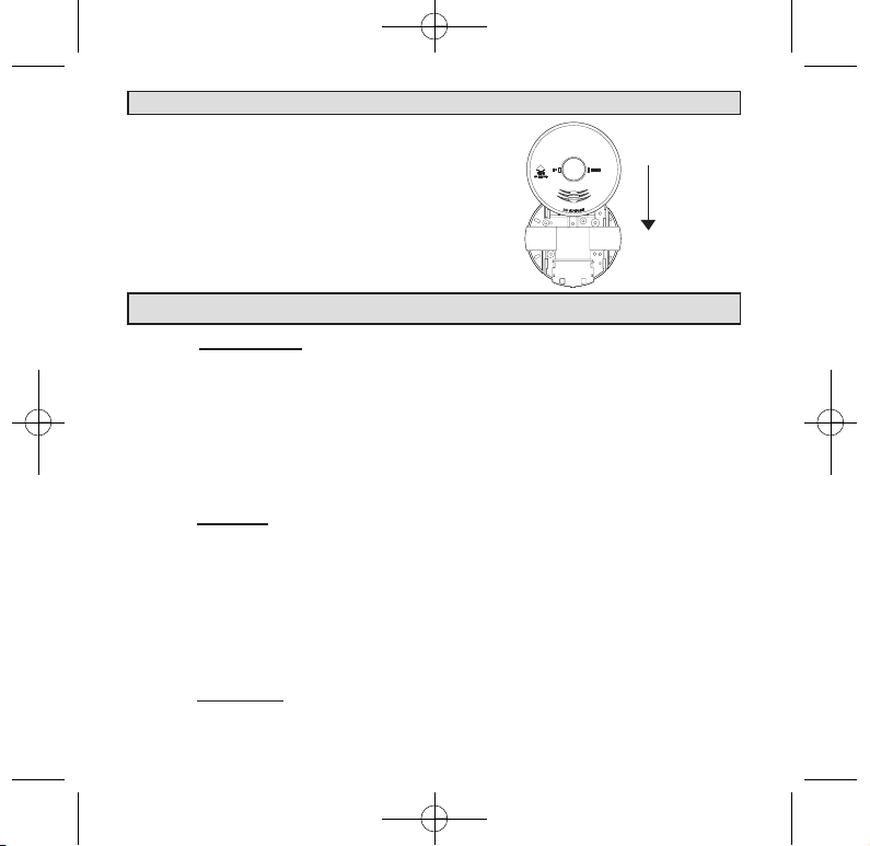
Figure 3: Wall mounting smoke alarm
For wall mounting, the connector must
be at the bottom. Ensure“ SLIDE TO
REMOVE ” arrow on the cover is
pointing upwards (vertical) as shown.
1398-7211-01_B2_V2:_ 2017.9.7 3:55 PM Page 9

10
6. OPERATION, TESTING AND MAINTENANCE
6.2 False Alarm Hush Control Feature:
Note: Dense smoke will override Hush control feature and sound a
continuous alarm.
6.2.1 The HUSH feature silences the smoke alarm from nuisance activation.
Eg, from dust, insects or cooking fumes.
6.2.2 The smoke alarm is desensitized by pressing the“ H U S H ” button.
6.2.3 After pressing the“ H U S H ” button, the alarm will silence
immediately for approximately 9 minutes to indicate the alarm is in the
temporary desensitized condition.
6.2.4 The smoke alarm will automatically reactivate after the hush period.
If particles of combustion are still present, the smoke alarm will sound
an alarm.
6.2.5 The “HUSH” feature may be used repeatedly until the air has cleaned
6.2.6 The red LED will flash every 10 seconds when in Hush mode.
6.2.7 If the battery is low, the smoke alarm will emit a low battery
chirp. Pressing the hush button will silence the low battery chirp
for up to 8 hours. Change the battery when battery is low.
WARNING: Before using the alarm HUSH feature, identify the source of
smoke and be certain that a safe condition exists.
6.2.8 This smoke alarm has a memory function that will inform you if the
alarm has sounded since the button was last pressed. The alarm memory
will cause the red LED to flash rapidly when the button is pressed. The
alarm memory is reset when the button is released.
1398-7211-01_B2_V2:_ 2017.9.7 3:55 PM Page 10

11
6. OPERATION, TESTING AND MAINTENANCE
6.3 Operating and Alarm Characteristics.
Function LED Status Sound emitted Recommendation
Normal Green ON
None
Green LED indicate the AC mains power is present.
Normal Red FLASHING every 5
minutes.
None Red LED flashes every 5 minutes is normal.
The smoke alarm performs a self test every 5 minutes.
The battery and electronics are tested for the life of the unit.
Local Alarm
Mode
Red light flashs. Smoke
alarm activated.
Repeat 3 long
beeps(ISO8201)
Indicate smoke alarm has activated and is in alarm mode.
The Red LED will be off after the alarm stops.
Interconnect
Alarm Mode
Red Light is OFF. Smoke
alarm activated.
Repeat 3 long
beeps(ISO8201).
Smoke alarm in full alarm, other interconnected units may
have activated the alarm. Check other smoke alarms or
devices.
Hush Mode Red light flashing every 10
seconds.
None HUSH button is pressed. Smoke alarm will silence
for approximately 9 minutes, After approximately
9 minutes will automatically exit hush mode.
Smoke Alarm
Memory
The red LED is pulsed
on three times every
40 seconds.
Pressing the button,
repeat chirp
Pressing the button, smoke alarm will chirp and red LED
pulse, and then upon release the button, the alarm memory
latch will be reset.
Low Battery Flashing red light every
5 minutes.
Chirp every 40
seconds.
For LIF5800/2 model replace the battery.
For LIF5800RL/2 model, replace with new smoke alarm.
If the smoke alarm is initiating alarm, please reference 5.1.2.
Low Battery
Hush
Flashing red light every 5
minutes.
None Pressing the hush button during low battery chirp will
silence the low battery chirp for up to 8 hours.
For LIF5800/2 model, replace the battery.
For LIF5800RL/2 model, replace with new smoke alarm.
If the smoke alarm is initiating alarm, please reference 5.1.2.
Chamber
Fault Mode
Flashing red light every 5
minutes.
Chirp 3 times
every 40 seconds
Clear alarm using a vacuum cleaner or compressed air,
if fault condition still exist after test, please replace with new
smoke alarm.
1398-7211-01_B2_V2:_ 2017.9.7 3:55 PM Page 11

12
7. BATTERY INSTALLATION , REPLACEMENT AND TEST
7.1 Battery Installation for LIF5800/2
7.1.1 The smoke alarm uses one 9V battery to automatically provide back-up
power to the alarm if AC power fails. The battery will operate the alarm for
approximately one to three months with AC power off.
7.1.2 The smoke alarm has a low battery indicator that will cause the unit to chirp
at approximately 40 second intervals for a minimum of 30 days. Missing battery
with main power connected will cause the unit to chirp approximately 40
second intervals.
7.1.3 Replace battery when chirping occurs. To ensure proper operation, the bat-
tery should be replaced once a year.
7.1.4 To replace battery, remove alarm from mounting base(see section 5.2) and
remove the battery from compartment. Replace the old battery with a new one.
7.1.4 The smoke alarm has a low battery hush feature. When the smoke alarm emits
a low battery chirp, pressing the Hush button will silence the low battery chirp
for 8 hours.
7.1.5 USE ONLY THE FOLLOWING 9-VOLT
ALKALINE BATTERIES FOR
REPLACEMENT:
EVEREADY/ENERGIZER 522
DURACELL MN1604, MX1604
These batteries can be purchased at
your local retail outlet or
supermarket.
Caution: Use only specified
batteries. Use of different
battery may have a detrimental
effect on operation or may cause the
battery to explode
resulting in injury or fire.
RED BATTERY LEVER
Australia Patent
S/N 2008200075
Australia Patent
S/N 2008200075
1398-7211-01_B2_V2:_ 2017.9.7 3:55 PM Page 12

13
7 BATTERY INSTALLATION , REPLACEMENT AND TEST
7.1.6 USE ONLY BATTERIES SPECIFIED ON THE LABEL .
7.1.7 Fold Red Battery Lever down into compartment with fresh replacement
battery. If the Red Battery Lever is not held down in the battery
compartment by the battery, the smoke alarm will not close and will not
be operational. Battery can only be inserted in one direction, ensure polarity is
correct.
WARNING: Use of inferior batteries or incorrect types may cause a malfunction of the
alarm. When replacing the battery and on reconnection of the detector to the base plate,
make sure that the detector is fully connected and flush with the base plate. Verify that
the Green LED is ON after reinstalling the alarm on the base plate.
7.2 Battery Test:
7.2.1 Switch off mains power. The Green LED on the smoke alarm will be OFF.
7.2.2 Test alarm by pressing on the Test Button for a few seconds. This should sound the
alarm.
7.2.3 If the battery module has a fault, the alarm will chirp every 40 seconds.
7.2.4 Watch the Red LED for about 5 minutes. It should flash at least once.
7.2.5 Switch on mains power only when smoke alarm passes the above tests. The Green
LED on the smoke alarm will come ON.
NOTE: NO USER REPLACEABLE PARTS INSIDE.
7.2.6 For LIF5800RL/2 ONLY
7.2.6.A Rechargeable battery must be checked periodically. We recommend a periodic
weekly battery test.
7.2.6.B Smoke alarm must be connected to mains power for 8 hours for the battery to be
fully charged.
7.2.6.C If the battery is low, the Red LED will flash every 40 seconds and sound a chirp.
We recommend that you check the AC mains power and allow up to 8 hours to
fully charge the battery. If chirping continues even after sufficient charging, we
recommend you replace the smoke alarm.
7.2.6.D
The rechargeable battery will supply the alarm for at least 7 days without AC power is
disconnected. In normal status, the battery has life of over 10 years.
1398-7211-01_B2_V2:_ 2017.9.7 3:55 PM Page 13

14
8. MAINTENANCE
8.1.1 Smoke alarms operate by monitoring the air and the environment around it.
Small particles in the air such as dust, fumes, small insects may cause the
smoke alarm to activate. We recommend the smoke alarm be regularly clean
at least once a month using a soft brush vacuum cleaner to ensure dust and
debris do not accumulate around the smoke alarm. Do not spray cleaners or
detergent into the smoke alarm.
Please note – Do not attempt to remove the cover of the smoke alarm to
clean inside. This will void your warranty.
8.1.2 Smoke alarms continually operates for the life of the product. It is designed
to work for 10 years under normal conditions. After 10 years of service, it is
recommended to replace the smoke alarm to ensure it continues to work
effectively. Check the manufactured date code and replace it after 10 years
from the date.
1398-7211-01_B2_V2:_ 2017.9.7 3:55 PM Page 14

15
9. 9V TERMINAL
WARNING: THIS TERMINAL IS NOT ISOLATED FROM THE MAINS SUPPLY.
This first terminal (Yellow) has a 9Vdc positive output and can be used for the following
applications: As an output to operate smoke alarm as an early warning indicator system.
The 9V terminal in this smoke alarm is intended for use with a security/fire alarm
panel where a signal from that panel can be used to activate a single Smoke Alarm or
interconnected Smoke Alarms to alert residents/occupants that an alarm has been acti-
vated elsewhere and there may be cause to evacuate the area. The diagram below
shows the 9V terminal and the Signal terminal, marked SW, connected to the N/O (nor-
mally open) contacts of a suitable relay, the coil of which when energized from an
extra-low voltage signal from an alarm panel, closes the contacts thereby activating the
Smoke Alarm(s). This can be an Early Warning Indicator System.
Note: The presence of an audible sound from the smoke alarm and the absence of a
flashing RED LED in the smoke alarm(s), means the smoke alarm(s) have been
activated externally. It is an Early Warning Indicator.
However, check also for the presence of fire or smoke in the vicinity of your
dwellings. If there is fire, follow actions in Section 14.
It is essential that the relay and associated base must be of a type providing effective
isolation between the coil and contacts (having an isolation voltage [Dielectric
Strength] of 4kV and creep/clearance distances of no less than 8mm between the coil
and contacts).
9.1 9V TERMINAL
1398-7211-01_B2_V2:_ 2017.9.7 3:55 PM Page 15
16
Wiring Instruction Showing Smoke Alarms Interconnected
and Used as part of an Early Warning Indicator System
9. 9V TERMINAL
The use of an unsuitable relay and base could also lead to an electric shock risk.
The wiring between the Smoke Alarm and the relay must be installed in accordance
with the relevant requirements of the SAA Wiring Rules, AS3000, for low voltage
(240V) conductors.
LOOP
N
SW
A
9V
LOOP
N
SW
A
9V
LOOP
N
SW
A
9V
1224
YELLOW
RED
WHITE
BLUE
ORANGE
ORANGE
YELLOW
RED
WHITE
BLUE
FIRE INDICATOR
PANEL
LOCAL ALARM PANEL
CONNECTION TO A
MAXIMUM OF 24 SMOKE ALARMS
FUSE ON
CIRCUIT
BREAKER
See installation manual
for isolation relay RK10A/9
N
SW
9V
24V
1398-7211-01_B2_V2:_ 2017.9.7 3:56 PM Page 16

17
10. REPAIRS AND SERVICES
10.1 If the smoke alarm is defective in any way, do not tamper with the unit.
Return the unit to your supplier (See warranty for instructions on in-warranty
returns). There will be a service charge for repairing units out of warranty.
Note: NO USER REPLACEABLE PARTS INSIDE.
11. GOOD SAFETY HABITS
The use of this product should not be seen as a substitute for basic safety precau-
tion in the prevention of FIRE.
There are situations where a smoke alarm may not be effective to protect against fire:
11.1 smoking in bed;
11.2 leaving children home alone;
11.3 cleaning with flammable liquids, such as petrol.
12. THE LIMITATIONS OF SMOKE ALARMS
12.1 Smoke alarms are devices that can provide early warning of possible devel-
oping fires at a reasonable cost.
12.2 Alarms have sensing limitations. Ionisation sensing alarm may detect
invisible fire particles (associated with fast flaming fires) sooner than
Photoelectric alarms. Photoelectric sensing alarm may detect visible fire
particles (associated with slow flaming fires) sooner than Ionisation alarms.
Home fires develop in different ways and are often unpredictable. Neither
type of alarm (photoelectric/ionisation) is always best and a given alarm may
not always provide warning of a fire.We strongly recommend that both
ionisation and photoelectric smoke alarms be installed to help insure maximum
detection of the various types of fires that can occur within the home.
12.3 Smoke alarms have certain limitations. For battery powered smoke alarms,
the battery must be in good condition and installed properly.
12.4 AC powered alarms will not operate if AC power has been cut off, such as by
an electrical fault, open fuse or circuit-breaker, or fire. However, the battery
back-up will activate the alarm if in good working order.
1398-7211-01_B2_V2:_ 2017.9.7 3:56 PM Page 17

18
12.5 Smoke alarms must be tested regularly to ensure that the batteries and alarm
circuit are in good operating condition.
12.6 Smoke alarms cannot provide an alarm if smoke does not reach the alarm.
Therefore, smoke alarm may not sense fires starting in chimneys, walls, on
roofs, on the other side of a closed door, or on a different floor.
12.7 If the alarm is located outside the bedrooms, or on a different floor, it may
not wake up a sound sleeper. A smoke alarm in the bedroom, therefore, is
recommended.
12.8 Smoke alarms have been significant in saving lives in many parts of the
world. However, U.S. Government research indicates that they may not give
early enough warning in up to 35% of fires. Hence, the use of this product
does not substitute for basic prevention and total protection.
12.9 Although smoke alarms can help save lives by providing early warnings of a
fire, they are not a substitute for an insurance policy.
12.10 This smoke alarm alone will not alert the hearing impaired. Use special
purpose smoke alarm with lights or vibrating devices, for those hard of hearing.
12.11 Heat alarms are available to offer greater security when used in conjunction
with smoke alarms.
12.12 Life safety from fire in residential occupancies is based primarily on early no-
tification to occupants of the need to escape, followed by the appropriate
egress actions by those occupants. Fire warning systems for dwelling units
are capable of protecting about half of the occupants in potentially fatal
fires. Victims are often intimate with the fire, too old or young, or physically
or mentally impaired such that they cannot escape even when warned early
enough that escape should be possible. For these people, other strategies such
as protection-in-place or assisted escape or rescue are necessary.
12. THE LIMITATIONS OF SMOKE ALARMS
1398-7211-01_B2_V2:_ 2017.9.7 3:56 PM Page 18
This manual suits for next models
1
Table of contents
Other PSA Smoke Alarm manuals

PSA
PSA LIFESAVER LIFWMB2 User manual

PSA
PSA LIFESAVER LIFPE10LP User manual

PSA
PSA Homeguard HG2000 User manual

PSA
PSA LIFESAVER 6000DCW User manual

PSA
PSA Lifesaver HA240 User manual

PSA
PSA Lifesaver LIF5000 User manual

PSA
PSA LIFESAVER LIF10YPEW User manual

PSA
PSA LIFESAVER 5800RF User manual

PSA
PSA LIFESAVER LIF5800ACF User manual

PSA
PSA Lifesaver 6800RL User manual


