Shanghai Sunny Hengping Scientific Instrument Co., Ltd UV2000 User manual
INSTRUCTION MANUAL FOR SPECTROPHOTOMETER
U
V2200
UV2000
V2200
V20
00
Before operating the unit, please read this manual thoroughly and retain it
for future reference.

PREFACE
We are grateful for your purchase of our spectrophotometer.
This instrument is intended to be utilized for research, development,
quality control, etc. primarily in fields of optical materials,
semiconductors, new materials, electronics and so on through
qualitative and quantitative analyses of samples diverse in kind and
size.
This instrument is intended for purpose of photometric analysis. Do not
use it for any other purpose.
This instruction manual has been prepared for users of how to handle
this instrument.
This instrument is designed for use by persons having a basic
knowledge of chemical analysis. Other persons should operate the
instrument in presence of someone who has such basic knowledge.
Remember that improper use of this instrument, chemicals, or samples
would result not only in wrong analytical data but in consequences
adverse to safety.
It is requested to carefully read through this manual to enable using this
instrument properly for a long time.
For installation/maintenance of this instrument, read instruction manual
carefully to attain a full understanding of instructions. Be sure to
observe cautionary instructions. Keep this manual handy for easy
reference when necessary.

INTRODUCTION TO THIS INSTRUCTION MANUAL
This manual is made up of 5 sections: Product specifications; Outside
view and internal structure; Installation; Operation; Maintenance and
inspection.
This instruction manual describes operating instructions and
precautions for this spectrophotometer.
Before using this instrument, be sure to read through this
instruction manual. First of all, read “SAFETY SUMMARY” included
at beginning of this manual for ensuring safety in operation of
spectrophotometer mainframe.
AFTER-SALES SERVICE
After-sales service For after-sales service of the instrument, contact local sales
representative. For ordering a replacement part, its name and number
need be specified.
Before using this manual,
keep the following in mind.
1. No part of this publication may be transmitted or reproduced in
any form or by any means without prior written permission of
Publisher.
2. If the instrument incurs damage due to usage contrary to one
instructed in this manual, manufacturer will not take any
responsibility. So customer must operate the instrument in
correct way.
3. This manual is neither for warranting enforcement of industrial
property rights and other rights nor for assenting to license of
enforcement.
Caution: Contents of this instruction manual are subject to change
without prior notice for further improvement of the
product, etc.

IMPORTANT –
1
IMPORTANT
1. PRECAUTIONS ON ELECTROMAGNETIC WAVE INTERFERENCE
1.1 Possible electromagnetic wave interference caused by this instrument
When this instrument is used a residential area or an adjacent area
thereto, it may cause interference to radio and television reception.
To prevent this, use specified system connection cables in strict
accordance with the instrument manual. The instrument is designed to
minimize possible electromagnetic wave interference caused by it if
specified cables are connected properly.
However, there is no guarantee that electromagnetic wave interference
will not be caused by the instrument. If the instrument does cause
interference to radio or television reception, which can be determined
by turning off and on the instrument, user is encouraged to try to correct
interference by one or more of following measures:
● Increase separation between the instrument and radio/TV
receiver.
● Connect the instrument to an outlet on a circuit different from that
to which radio/TV receiver is connected.
1.2 Possible electromagnetic wave interference affecting by this instrument
If this instrument is used near an intense electromagnetic source,
interference noise may be given to the instrument to incur an adverse
effect on its performance or functionality.
To prevent this, use specified system connection cables in strict
accordance with instruction manual. The instrument is designed to
minimize possible electromagnetic wave interference affecting it if
specified cables are connected properly.
However, there is no guarantee that electromagnetic wave interference
will not occur in this instrument. If the instrument does occur
electromagnetic wave interference, which can be determined by turning
on and off possible sources of electromagnetic wave interference
nearby, user is encouraged to try to correct interference by one or more
of following measures:
● Reorient the instrument.
● Increase separation between the instrument and possible
sources of electromagnetic wave interference.
● Increase separation between power cable of the instrument and
possible sources of electromagnetic wave interference.
● Connect the instrument to an outlet on a circuit different from that
to which possible sources of electromagnetic wave interference
are connected.
● Confirm that any other device connected with the instrument is
not affected by electromagnetic wave interference.

IMPORTANT –
2
2. WARRANTY ON PRODUCT
This instrument is warranted to operate according to specifications
given in instruction manual, provided it is used in accordance with
instructions described in manual.
(1) Scope of Warranty
(a) Any parts which prove to be defective in design or
workmanship during warranty period will be repaired
without charge.
(b) A substitute part may be used for repair, or replacement
with an equivalent product may be made instead of repair.
(c) Such system components as a personal computer and
printer to be updated frequently for improvement may not
be available in original versions at time of replacement.
(2) Warranty Period
One year from date of initial delivery.
Consumables such as tungsten lamp and Deuterium lamps are
excluded from warranty.
(3) Availability of Technical Support Service
Technical support service for this instrument is available within
regular working hours on workdays predetermined by us.
(4) Limitations and Exclusions on Warranty
Note that this warranty is void in the following cases, even if they
occur within warranty period.
(a) Failure due to operation at a place not meeting
installation requirements specified by us.
(b) Failure due to power supply voltage/frequency other than
specified by us or due to abnormality in power supply.
(c) Corrosion or deterioration of the tubing due to impurities
contained in reagent, gas, air or cooling water supplied by
the user.
(d) Corrosion of electric circuits or deterioration of optical
elements due to highly corrosive atmospheric gas.
(e) Failure due to use of hardware, software or spare parts
other than supplied by us.
(f) Failure due to improper handling or maintenance by user.
(g) Failure due to maintenance or repair by a service agent
not approved or authorized by us.
(h) After disposal of this instrument, or after its resale without
our approval.
(i) Consumables, and failure of parts that have reached the
end of specified useful life.
(j) Failure of parts excluded from warranty in instruction
manual or other documents.
(k) Failure due to acts of God, including fire, earthquake,
storm, lightning, social disturbance, riot, crime,
insurrection, war (declared or undeclared), radioactive
pollution, contamination with harmful substances, etc.
(l) Failure of the hardware, or damage to system software,
application software, data or hard disk due to computer
virus infection.

IMPORTANT –
3
(m) Failure of personal computer connected with instrument,
or damaged to system software, application software,
data or hard disk due to power interruption or momentary
power voltage drop caused by lightning or the like.
(n) Failure of personal computer connected with instrument,
or damage to the system software, application software,
data or hard disk due to disconnection of main power to
personal computer without taking specified normal
shutdown procedure.
(5) Disclaimer of Warranty
(a) Any express warranties other than explicit conditions
indicated in (1) are excluded from this warranty.
Any other implied warranties of merchantability and
fitness for a particular purpose are not included in this
warranty.
No liability is assumed for direct or indirect damages
arising out of explicit or implied warranties.
(b) Oral or written information or advice given by our dealers,
distributors, agents or employees without our express
permission shall not create a warranty or in any way
increase the scope of this warranty.
3. OTHER PRECAUTIONS
3.1 Handling of chemicals and samples
(1) User is responsible for following relevant legal standards and
regulations in handling, storage and discarding of chemicals and
samples used in analytical operations of this instrument.
(2) Reagents, standard solutions and accuracy – control samples
shall be handled, stored and discarded as instructed by
respective supplies.
3.2 Notice on instruction manuals
(1) Information contained in instruction manuals furnished with the
instrument is subjected to change without notice for product
improvement.
(2) This manual is copyrighted by our company with all rights
reserved.
(3) No part of this manual may be reproduced or transmitted in any
form or by any means without our express written permission.
3.3 Trademark Acknowledgements
Microsoft, Windows, Microsoft Excel, Microsoft Word and Windows XP,
Windows 7, Windows 8 and Windows 10 are registered trademarks,
trademarks or trade names of Microsoft Corporation, USA, while other
company names and product names are those of respective
companies.

SAFETY –
1
SAFETY SUMMARY
PRECAUTIONS ON SAFETY
Before using this spectrophotometer, be sure to read following safety
instructions carefully.
GENERAL SAFETY GUIDELINES
● Follow all operating procedures provided in this manual.
● Maintenance of the product shall be carried out by qualified
service personnel therefore.
● Be sure to observe warnings indicated on product and in
instruction manual. Failure to do so could result in personal injury
or damage to the product.
● The hazard warnings which appear on warning labels on the
product or in manual have one of the following alert headings
consisting of an alert symbol and signal word WARNING and
CAUTION.
WARNING :
Indicates a potentially hazardous situation
which, if not avoided, can result in death or
serious injury.
CAUTION :
Indicates a hazardous situation which, if not
avoided, will or can result in minor or moderate
injury, or serious damage to the product.
“NOTICE” and “Note” are heading words which do not concern
personal safety directly.
NOTICE: Used to indicate an instruction for preventing damage to
the product.
NOTE: Used to indicate an instruction for ensuring correct use of
the product and accurate analysis therewith.
● Do not modify the product, replace parts that are not user –
serviceable, use non – specified parts, nor remove safety
devices, as it could be hazardous.
● Maintenance should be referred to our qualified service
personnel.
● Do not perform any operation or action other than described in
the instruction manual. When it doubt, please contact our sales
representative or service office nearest you.

SAFETY –
2
SAFETY SUMMARY
GENERAL SAFETY GUIDELINES (Con’d)
● When using a chemical for analytical operation, be sure to
provide proper ventilation in the laboratory room as per local
requirements. Inadequate ventilation could endanger human
● Keep in mind that the hazard warning in manual or on the
product cannot cover every possible case, as it is impossible to
predict and evaluate circumstances beforehand.
Be alert and use your common sense.
WARNING
This instruction manual contains the following cautious instructions.
● Electric Shock in Contact with Dangerous High Voltage.
In contact with power supply voltage, you may receive an electric
shock to cause fatal or serious injury.
Before connecting power cord, make sure that the uint is turned
off.
● Electric Shock in Contact with Dangerous High Voltage.
In contact with Deuterium lamp power supply voltage (120 V),
you may receive an electric shock to cause fatal or serious injury.
Before connecting Deuterium lamp power cord, make sure that
the unit is turned off.
CAUTION
● Burn in Contact with High Temperature
Deuterium lamp and tungsten lamp reach a high temperature.
They can burn you if touched.
Before replacing or adjusting lamp, turn off the unit and wait until
it cools down sufficiently.
● Fatigue on Long Use
Watching the screen in the same posture for a long time
accumulates fatigue in your eyes or body. For long use, take a 10
to 15 minutes recess every hour for your health.
● Oxygen Deficiency due to Presence of Nitrogen
(when using Ultra Violet region measurement system)
If nitrogen purging is carried out for long hours in a narrow room
without operating an exhaust duct, oxygen concentration in room
will decrease and an oxygen deficiency could result.
Be sure to operate an exhaust duct or else open a window during
purge for ventilation purposes.

SAFETY –
3
SAFETY SUMMARY
REMARKS ON SAFETY OF SPECTROPHOTOMETER
Electricity
(1) Confirm power supply to spectrophotometer.
Fluctuation in voltage or noise on power line would not only affect spectrophotometer mainframe
adversely but also cause an accident.
(2) Be sure to provide grounding connection along with power connection.
(3) High – voltage circuits are used inside spectrophotometer. Do not open any other cover than
necessary for operation.
Fire
Avoid smoking and using a fire in the vicinity of spectrophotometer.
Data Backup
Data may become unusable in case of instrument failure or misoperation.
It is recommended to transfer data from hard disk to a flash disk periodically. Transfer of data is called
backup.
To avoid misoperation, secure a free space of 100MB or so on the hard disk as a software word area at
all times.
Computer Virus
If programs or data has suddenly been destroyed, if an unexpected operation takes place or if an
abnormal display appears on screen, your personal computer may have been infiltrated by a computer
virus. Computer virus is a rogue program that secretly invades a personal computer and operates it
willfully while destroying memorized data.
A program for eliminating the virus is called vaccine program.
There is a possibility of contamination with a program including a computer virus, or by using an
exchangeable recording medium such as a flash disk that contains a computer virus. Also, it is possible
to transmit the virus from one personal computer to another via communication or recording media. So
avoid using a program or recording medium that might include a virus.
Carry out check using a vaccine program if there is a possibility of contamination with a virus. But
depending on type of vaccine program, it may be impossible to eliminate virus.
It is therefore recommended to back up contents of hard disk beforehand.
Power Failure
A power failure or momentary voltage drop of power supply due to lighting, etc. may cause failure of
personal computer used with the instrument and also damages system software, application software
and other data. To avoid such problems, it is recommended to use an AC uninterruptible power
source.
Personal Computer (PC)
Do not t urn off PC power supply alone. If PC power supply is turned off during access to hard disk or
flash disk, PC may be damaged and data or software stored in it may be destroyed. To turn off PC
power supply, be sure to complete spectrophotometer control and data processing program before
taking shutdown procedure for system software.

– – - 1 -
PRECAUTIONS ON HANDLING
1. CAUTION ON SAFETY
Be sure to entrust internal checks of the instrument to a serviceman for
ensuring safety.
Do not gaze at light source (Tungsten and Deuterium lamps) directly.
Particular attention must be paid to Deuterium lamp because it radiates
intense ultraviolet rays.
2. CAUTION ON USE
Optical parts are fragile. Besides, control and data processing sections
comprise high – density electronics. Therefore, precautions below must
be taken without fail.
(1) Avoid giving shock or vibration to optical parts. Do not breathe
on optical parts or touch them with bare hands.
(2) For removing dust from optical parts, blow it off by using a hand
sprayer which jets out clean dry air. Do not wipe them with a
cloth or the like.
(3) The operating temperature must be within 5
0
C
to 35
0
C.
However, optimum condition is restricted to a range to 200C to 250C.
Hence, installation in an air – conditioned room is recommended.
(4) Operating humidity must be within 45 to 85%.
(5) Atmosphere must not be filled with acidic, alkaline or other
metal-corroding vapor.
(6) Avoid a location filled with vapor of organic solvent (particularly
benzine and thinner).
(7) Avoid direct sunlight. (Otherwise optical performance might
deteriorate. Do not locate the instrument near a window
whenever possible.)
(8) Do not allow strong vibrations nor shocks beyond a level which
can be sensed by the human body. (Otherwise delicate
adjustment mechanism might run out of order.)
(9) Protect the instrument cover from excessive heat (beyond
700C) radiated form a gas burner, heater, oven or the like.
(10)
The instrument must be located away from equipment which
generates a strong electric field (such as an electric welding
machine, high-frequency electric furnace and pole transformer).
(11)
Dusty environment is unallowable. (Otherwise adequate optical
performance might not be ensured.)
(12)
Line voltage must not fluctuate suddenly (otherwise noise might
increase). Its fluctuation must be within ±10%.
(13)
Do not turn on/off frequently power supply to a motor (stirrer,
vibrator, etc.) without a noise - preventive device in same power
line as the instrument’s.
(14)
The installation plane must be level and capable of bearing a
weight of about 25Kg or more.
(15)
Minimum power requirements are 90VA. But a higher power
capacity (1KVA or more) must be prepared in order to allow
another instrument to share power line.
(16)
Fluctuation of power frequency must be within +0.3 to –1.0% of
rated frequency (50 or 60 Hz).

– – - 2 -
3. CAUTION ON STORAGE OF INSTRUMENT
3.1 Checks upon Completion of Measurement
(1)
Turn off the unit and disconnect power from line power outlet.
(2)
Contamination of the sample compartment is inevitable. There
might be a chance of an undesired trouble occurring due to
ingress of foreign material or dust. To prevent this, check sample
compartment for contamination as frequently as possible.
(3)
Take off cell holder component, and clean it.
Loosen cell holder handle with anticlockwise, and pull it out.
Open sample compartment cover. Loosen 2 pcs of M4 Screws
which are used to fix cell holder component, you can take off cell
holder component.
To mount cell holder component, please set wavelength value to
546.0 nm, and there is a light beam with bright green color in
sample compartment. Be sure the green light beam must enter
into the middle aperture of cell holder, and you can mount cell
holder component with 2 pcs of M4 screws.
(4)
Cleaning of lenses
For cleaning, wipe lenses with soft paper or cloth using a 1:1
mixture of alcohol and ether.
First of all, your hands must be clean.
(5)
Put dust-preventive cover or a protective sheet of a proper size
on the instrument.
Caution: In case an organic solvent is placed in sample
compartment, it must be taken out of compartment.
Never leave it inside.
Wash the rectangular sample cells with
petroleum-ether, dry them with gently paper and
then put them into the colorimetric box after using.
3.2 Precautions for Long-Term Storage
(1)
Protect the instrument from high temperature (70
0
C or higher),
low temperature (-200C or lower), high humidity (80% or higher),
and strong vibrations throughout storage.
(2)
Be sure to put dust-preventive cover or a sheet cover on the
instrument.
(3)
Protect the instrument interior from acidic, alkaline or other
harmful gases.
(4)
Avoid a location under a strong magnetic field.
(5)
A dusty location is inappropriate for storage.
(6)
During storage, the instrument must be free from direct sunlight.

i
Table of Contents
Section Title Page
1 Product specifications······································································ 1
1.1 Technical specifications···································································· 1
1.2 Standard configurations···································································· 1
1.3 UV-Solution software (Optional) ························································· 1
2 OUTSIDE VIEW AND INTERNAL STRUCTURE······································ 2
2.1 Front – right view·············································································· 2
2.2 Rear view························································································· 2
2.3 Internal structure·············································································· 3
2.3.1 Internal structure of VIS spectrophotometer·············································· 3
2.3.2 Internal structure of UV-VIS spectrophotometer········································· 3
2.4 Optics schematic diagrams································································ 4
2.4.1 Optics schematic diagrams of VIS spectrophotometer································ 4
2.4.2 Optics schematic diagrams of UV-VIS spectrophotometer··························· 4
3 INSTALLATION················································································· 5
3.1 Power requirements·········································································· 5
3.1.1 Line voltage······················································································· 5
3.1.2 Frequency························································································· 5
3.1.3 Power capacity··················································································· 5
3.2 Conditions for installation·································································· 5
3.2.1 Installation area·················································································· 5
3.2.2 Installation plane················································································· 5
3.2.3 Environment at place for installation························································ 5
3.3 Check of contents············································································· 6
3.3.1 Check of packing················································································ 6
3.3.2 Check against standard configurations···················································· 6
3.4 Connection of power cord·································································· 6
3.5 Check after installation······································································ 6
3.6 Initialization····················································································· 6
3.6.1 Description of item to be tested······························································ 7
3.6.2 Initializing interface············································································· 7
3.6.3 Main interface·····················································································
8
4 OPERATION····················································································· 9
4.1 Function of each key on main interface················································
9
4.2 Absorbance measurement mode·························································
10
4.2.1 Testing directly without measurement data list···········································
10
4.2.1.1 Setting wavelength value······································································ 10
4.2.1.2 Blanking (Adjusting 0.000Abs) ······························································ 10
4.2.1.3 Testing······························································································ 10
4.2.2 Testing with measurement data list························································· 10
4.2.2.1 Setting wavelength value······································································ 10
4.2.2.2 Blanking (Adjusting 0.000Abs) ······························································ 10
4.2.2.3 Testing······························································································ 11
4.2.2.4 Clearing all data··················································································
11

ii
Table of Contents
(cont’d)
Section Title Page
4.3 Transmittance measurement mode······················································ 11
4.3.1 Testing directly without measurement data list···········································
11
4.3.1.1 Setting wavelength value······································································ 11
4.3.1.2 Blanking (Adjusting 100.0%T) ······························································· 11
4.3.1.3 Testing······························································································ 11
4.3.2 Testing with measurement data list························································· 12
4.3.2.1 Setting wavelength value······································································ 12
4.3.2.2 Blanking (Adjusting 100.0%T) ······························································· 12
4.3.2.3 Testing······························································································ 12
4.3.2.4 Clearing all data··················································································
12
4.4 Coefficient method············································································ 13
4.4.1 Reading concentration value directly······················································· 13
4.4.1.1 Setting wavelength value····································································· 13
4.4.1.2 Blanking (Adjusting 0.000A) ································································· 14
4.4.1.3 Inputting known concentration value······················································· 14
4.4.1.4 Reading unknown sample concentration value directly······························· 14
4.4.2 Testing concentration factor “K” with known concentration value··················· 15
4.4.2.1 Setting wavelength value······································································ 15
4.4.2.2 Blanking (Adjusting 0.000A) ································································· 15
4.4.2.3 Inputting known concentration value······················································· 15
4.4.2.4 Getting concentration factor “K” with known concentration value··················· 16
4.4.3 Setting coefficient curve with known coefficient value································· 16
4.4.3.1 Setting coefficient value······································································· 16
4.4.3.2 Saving coefficient curve······································································· 16
4.4.3.3 Clearing all coefficient curve································································· 17
4.4.4 Testing with coefficient curve································································ 17
4.4.4.1 Opening coefficient curve····································································· 17
4.4.4.2 Testing······························································································ 18
4.4.4.2.1 Testing directly without measurement data list···········································
18
4.4.4.2.1.1 Setting wavelength value······································································ 18
4.4.4.2.1.2 Blanking (Adjusting 0.000A) ································································· 18
4.4.4.2.1.3 Testing······························································································ 18
4.4.4.2.2 Testing with measurement data list························································· 19
4.4.4.2.2.1 Selecting concentration unit································································· 19
4.4.4.2.2.2 Setting wavelength value······································································ 19
4.4.4.2.2.3 Blanking (Adjusting 0.000Abs) ······························································ 19
4.4.4.2.2.4 Testing····························································································· 19
4.4.4.2.2.5 Clearing all data················································································· 19

iii
Table of Contents
(cont’d)
Section Title Page
4.5 Standard curve method······································································ 19
4.5.1 Creating standard curve······································································· 21
4.5.1.1 Selecting concentration unit·································································· 21
4.5.1.2 Setting wavelength value······································································ 21
4.5.1.3 Inputting concentration value of standard sample·······································
21
4.5.1.4 Inputting standard sample name···························································· 22
4.5.1.5 Blanking (Adjusting 0.000Abs) ······························································ 22
4.5.1.6 Getting absorbance value of standard sample···········································
22
4.5.1.7 Displaying standard curve···································································· 23
4.5.1.8 Revising standard sample information····················································· 23
4.5.1.9 Saving standard curve········································································· 23
4.5.1.10 Clearing all standard curve····································································
24
4.5.2 Testing with standard curve··································································· 24
4.5.2.1 Opening standard curve······································································· 24
4.5.2.2 Entering measurement data list of standard curve····································· 25
4.5.2.3 Setting wavelength value······································································ 25
4.5.2.4 Blanking (Adjusting 0.000A) ································································· 25
4.5.2.5 Testing······························································································ 25
4.5.2.6 Inputting unknown sample name···························································· 26
4.5.2.7 Clearing all data················································································· 26
4.6 Option····························································································· 27
4.6.1 Option of VIS spectrophotometer··························································· 27
4.6.1.1 Operation version··············································································· 27
4.6.1.2 Date and time···················································································· 27
4.6.1.3 Initialize machine················································································ 27
4.6.1.4 Default setting···················································································· 27
4.6.1.5 Language·························································································· 27
4.6.2 Option of UV-VIS spectrophotometer·······················································
28
4.6.2.1 Operation version··············································································· 28
4.6.2.2 Date and time···················································································· 28
4.6.2.3 Initialize machine················································································ 28
4.6.2.4 Default setting···················································································· 28
4.6.2.5 Language·························································································· 28
4.6.2.6 Lamp switch wavelength······································································ 28
5 MAINTENANCE AND INSPECTION······················································ 29
5.1 Message during initialization······························································ 29
5.2 Troubleshooting guide······································································· 31
5.3 Replace lamp and fuse······································································ 33
5.3.1 Replacement of deuterium lamp···························································· 33
5.3.2 Replacement of tungsten lamp······························································ 34
5.3.3 Replacement o f fuse·········································································· 35

1
1. Product specifications
1.1 Technical specifications
Model
V2000
V2200
UV2000
UV2200
Monochromator C-T type, 1200 L/mm grating
Detector Silicon detector
Display 4.3” color LCD, touch screen
Wavelength calibration Automatic at start
Wavelength display 0.1 nm
Light source Tungsten lamp(2000h, 20W/12V) Deuterium discharge tube(1000h), Tungsten lamp(2000h, 20W/12V)
Lamp change point / Can be set, 294 nm - 365 nm
Wavelength range 325-1100 nm 200-1100 nm
Slit width 4 nm 2 nm 4 nm 2 nm
Wavelength accuracy ±2.0 nm ±1.5 nm ±2.0 nm ±1.5 nm
Wavelength repeatability 1.0 nm 0.8 nm 1.0 nm 0.8 nm
Measurement range 0 ~ 200%T, -0.301 ~ 3.000Abs, -9999 ~ 9999C, -9999 ~ 9999F
Photometric accuracy ±0.5 %T ±0.3 %T ±0.5 %T ±0.3 %T
Photometric repeatability 0.2 %T 0.2 %T 0.2 %T 0.2 %T
Stray light 0.5 %T (at 360 nm) 0.3 %T (at 360 nm) 0.5 %T (at 220nm and 360 nm) 0.3 %T (at 220nm and 360 nm)
Baseline flatness / ≤±0.004 Abs (With UV-Solution) / ≤±0.004 Abs (With UV-Solution)
Stability ≤0.002 Abs / half hour (at 500 nm, after 2 hours energization)
Data output Digital, USB port
Power 220V
10% 50Hz 75VA / 110V
10% 60Hz 75VA 220V
10% 50Hz 90VA / 110V
10% 60Hz 90VA
Standard sample holder 4-position sample holder
Actual dimensions 470 W X 380 D X 225 H mm, (18.6 W x 15.0 D x 8.9 H in)
Shipping dimensions 650 W X 539 D X 370 H mm, (25.6 W x 21.3 D x 14.6 H in)
Net weight 10.0 Kg (22.0 lbs) 10.0 Kg (22.0 lbs) 10.5 Kg (23.1 lbs) 10.5 Kg (23.1 lbs)
Gross weight 14.0 Kg (30.8 lbs) 14.0 Kg (30.8 lbs) 14.5 Kg (31.9 lbs) 14.5 Kg (31.9 lbs)
1.2 Standard configurations (“●” means this item is standard configurations; “/” means this item is not standard configurations)
Item Quantity
V2000
V2200
UV2000
UV2200
Instrument 1 ● ● ● ●
Power cord 1 ● ● ● ●
Quartz cell (10 mm path length) 2 / / ● ●
Glass cell (10 mm path length) 4 ● ● ● ●
Fuse 2 ● ● ● ●
Instruction manual for instrument 1 ● ● ● ●
1.3 UV-Solution software (Optional) (“●” means this item can be configured with this instrument; “/” means this item cannot be configured with this instrument)
Item Quantity
V2000
V
2200
UV2000
UV2200
UV-Solution Software disk 1 / ● / ●
Instruction manual for software 1 / ● / ●
USB cable 1 / ● / ●
Watch dog 1 / ● / ●

2
2. OUTSIDE VIEW AND INTERNAL STRUCTURE
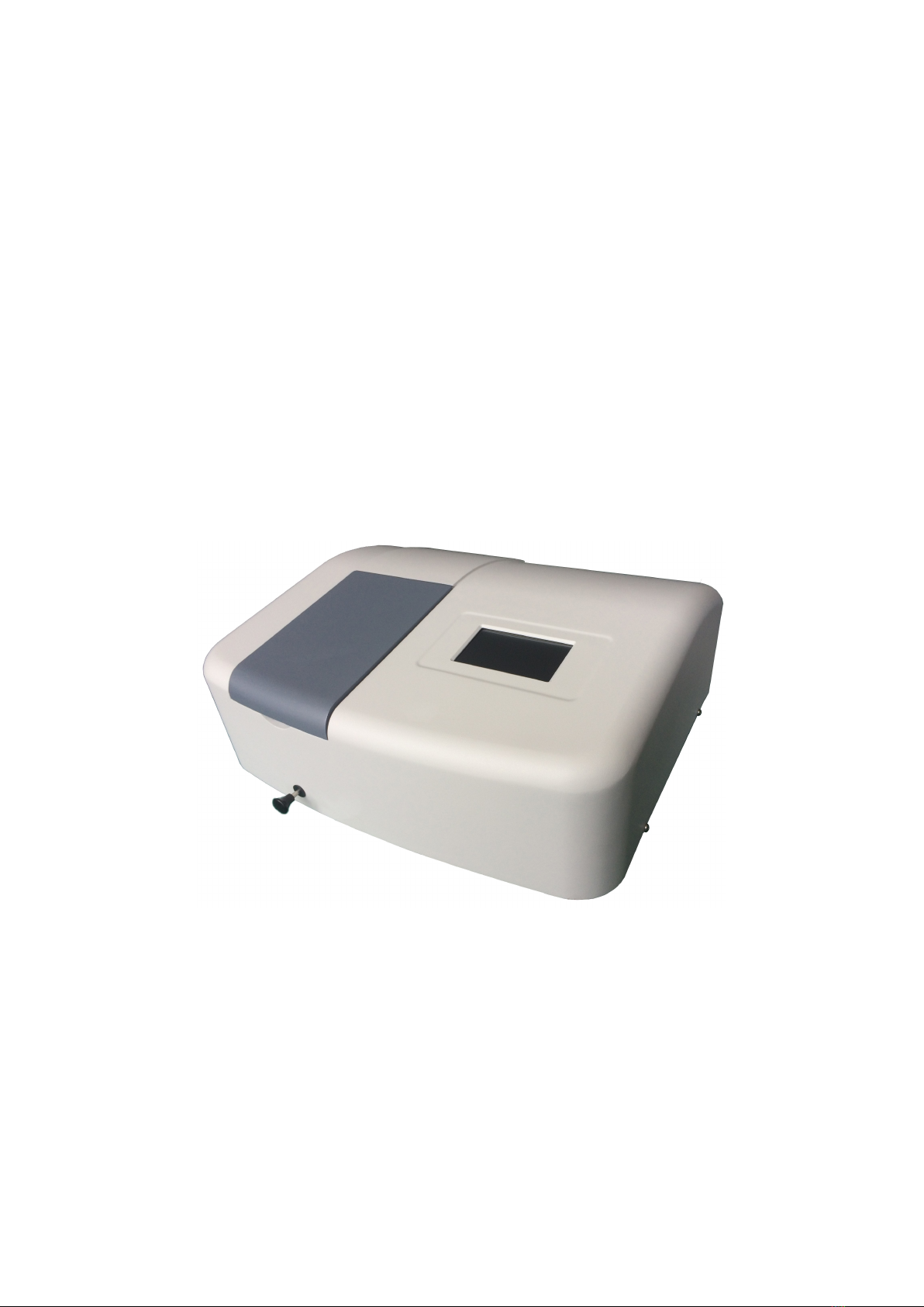
2.1 Front – right view
Figure 2 – 1 Front – right view
1) Sample Compartment cover
2) Cell Holder Handle
To use to change cell holder position.
3) Screw
Used to fix the cover.
4) 4.3” LCD touch screen
Used to display the information of the instrument.
2.2 Rear view
Figure 2 – 2 Rear view
1) Fan
2) USB port
Used to link with PC.
3) Power switch

3
2.3 Internal structure
2.3.1 Internal structure of VIS spectrophotometer
Figure 2 – 3 Internal structure of VIS spectrophotometer
1) Main board
2) Switch power supply for mainboard and tungsten lamp
3) Tungsten lamp(12V/20W)
4) Toroidal mirror
5) Fan
6) Pre-amplifier circuit board
7) Sample holder
8) Monochromator
2.3.2 Internal structure of UV-VIS spectrophotometer
Figure 2 – 4 Internal structure of UV-VIS spectrophotometer
1) Main board
2) Switching power supply for deuterium lamp
3) Switching power supply for mainboard and tungsten lamp

4
4) Deuterium lamp(DD2.5Z)
5) Tungsten lamp(12V/20W)
6) Toroidal mirror
7) Fan
8) Pre-amplifier circuit board
9) Sample holder
10) Monochromator
2.4 Optics schematic diagrams
Monochromatic light emitted from monochromator has achieved an ultra-small stray light without
degrading high resolution through series connecting that of monochromator grating. Monochromatic
light is led into sample compartment, in which beam passes through reference and unknown sample.
Beam transmitted through reference and sample is incident on detector, namely a solid silicon
photodiode.
2.4.1 Optics schematic diagrams of VIS spectrophotometer
Figure 2 – 5 Optics schematic diagrams of visible spectrophotometer
2.4.2 Optics schematic diagrams of UV-VIS spectrophotometer
Figure 2 – 6 Optics schematic diagrams of UV-VIS spectrophotometer

5
3. INSTALLATION
3.1 Power requirements
3.1.1
Line voltage 220V
10%
110V
10%
Fluctuation must be within ±10% of rated level.
3.1.2
Frequency 50 or 60 Hz
Fluctuation must be within +0.3 to –1.0% of rated level.
3.1.3
Power capacity Suggest to prepare 1KVA or more since power may be shared with
another instrument.
3.2 Conditions for installation
3.2.1
Installation area At back - side of the instrument, it is desirable to secure enough space
(100mm or more) to emit heat.
3.2.2
Installation plane
Installation plane must be level and capable of bearing a weight of
about 25Kg or more.
3.2.3
Environment at place for installation
1)
Operating temperature
50C to 350C.
For stable measurement, room temperature should preferably be
controlled within a range of 200C to 250C by an air-conditioner.
2)
Operating humidity
45% to 85%
3)
Storage temperature
-200C to 700C.
4)
Atmosphere
a. Must be free from acidic, alkaline and other vapors which
will corrode metals heavily.
b. Must not contain the vapor of organic solvent (particularly
benzine and thinner) which will dissolve coating.
5)
Other general cautions
a. Avoid direct sunlight and provide as large a distance as
possible from a room window.
b. A strong vibration or shock that can be felt by human body
must not be transmitted to the instrument.
c. Avoid vicinity of heat generating apparatus such as a gas
burner, electric heater or oven in order to prevent instrument
cover being heated (beyond 700C).
d. Avoid vicinity of instruments which generate a strong
electric field (such as an electric welding machine, high
frequency furnace and pole transformer).
e. Dusty environment is unallowable.
f. The line voltage must be free from wide and sudden
fluctuations.
g. Do not turn on and off frequently electric instruments (stirrer,
vibrator, etc.) which are not provided with a noise –

6
preventive device in same power line as for the instrument.
Caution: Optical parts are very fragile, and control section
incorporates high – density electronic circuit components
which function as a computer. To protect these parts,
above cautions must be observed strictly.
3.3 Check of contents
3.3.1
Check of packing
Please ensure packing is intact before unpacking, if packing is
damaged please connect transportation department.
3.3.2
Check against standard configurations
After unpacking (Suggest to keep the paperboard container), check the
contents of delivery against standard configurations. If any part is lost
or damaged or fall short of specifications, or if you have a question,
please report to the agent.
Warning:
Use of proper hardware and accessories is required as
specified. Proper installation according to instructions is
required. Improper installation may result in serious
personal injury.
3.4 Connection of power cord
Plug power cord into power inlet.
Caution: Be sure to turn off the unit before plugging in power cord.
3.5 Check after installation
Installation must have been completed according to instruction given
above. Before proceeding to measurement, however, reconfirm that
installation has been made correctly. Please confirm following
contents.
1) There is no abnormality at installation location.
2) The line voltage is confirmed and set correctly.
3) The cords are connected correctly.
4) Connection of power cord is right.
5) After confirming 1) to 4), check if anything is set in sample
compartment so as to block beam or if there is any other anomaly.
Note: After checking inside of sample compartment, please
ensure sample compartment cover is closed properly.
3.6 Initialization
After completion of all confirmations in above steps, system is allowed to
be energized by following procedures.
The instrument will emit a slight click sound when it is turned on, and
tungsten lamp is ignited simultaneously. After about several seconds, the
unit will emit another slight click sound, and deuterium lamp is ignited.
This manual suits for next models
3
Table of contents


