Sharp MD-SR50HBL User manual

MD-SR50H/50W/60E/60W
– 1 –
CONTENTS Page
SAFETY PRECAUTION FOR SERVICE MANUAL ............................................................................................................... 2
SPECIFICATIONS ................................................................................................................................................................. 3
NAMES OF PARTS ............................................................................................................................................................... 4
OPERATION MANUAL .......................................................................................................................................................... 5
DISASSEMBLY...................................................................................................................................................................... 8
REMOVING AND REINSTALLING THE MAIN PARTS......................................................................................................... 9
ADJUSTMENT ...................................................................................................................................................................... 10
NOTES ON SCHEMATIC DIAGRAM .................................................................................................................................. 23
TYPES OF TRANSISTOR AND DIODE .............................................................................................................................. 23
VOLTAGE ............................................................................................................................................................................ 24
BLOCK DIAGRAM ............................................................................................................................................................... 25
SCHEMATIC DIAGRAM ...................................................................................................................................................... 26
WIRING SIDE OF P.W.BOARD........................................................................................................................................... 28
WAVEFORMS OF MD CIRCUIT ......................................................................................................................................... 31
TROUBLESHOOTING ......................................................................................................................................................... 32
FUNCTION TABLE OF IC.................................................................................................................................................... 35
PARTS GUIDE/EXPLODED VIEW
PACKING METHOD (MD-SR50H for U.K./SR60E Only)
SERVICE MANUAL
SHARP CORPORATION
No. S2006MDSR50H/
This document has been published to be used
for after sales service only.
The contents are subject to change without notice.
MD-SR50H(BL)
MD-SR50H(S)
MD-SR50H(YR)
MD-SR50W(BL)
MD-SR50W(S)
MD-SR60E(GL)
MD-SR60W(S)
• In the interests of user-safety the set should be restored to its
original condition and only parts identical to those specified be
used.
Illustration: MD-SR50H/SR50W
Illustration: MD-SR60E/SR60W

MD-SR50H/50W/60E/60W
– 2 –
Figure 2-1 Figure 2-2
Precaution to be taken when replacing and servicing the Laser Pickup.
The AEL (Accessible Emission Level) of Laser Power Output for this model is specified to be lower than Class I Requirements.
However, the following precautions must be observed during servicing to protect your eyes against exposure to the laser beam.
(1) When the cabinet has been removed, the power is turned on without a compact disc, and the Pickup is on a position
outerthan thelead-in position,the Laserwill lightfor severalseconds todetect adisc. Donot lookinto thePickup Lens.
(2) The Laser Power Output of the Pickup inside the unit and replacement service parts have already been adjusted prior
to shipping.
(3) No adjustment to the Laser Power should be attempted when replacing or servicing the Pickup.
(4) Under no circumstances look directly into the Pickup Lens at any time.
(5) CAUTION-Useofcontrols or adjustments, or performance of proceduresotherthanthosespecified herein may result
in hazardous radiation exposure.
SAFETY PRECAUTION FOR SERVICE MANUAL
VARO ! Avattaessa ja suojalukitus ohitettaessa olet alttiina näkymättömälle lasersäteilylle. Älä katso säteeseen.
VARNING! Osynlig laserstralning när denna del är öppnad och spärren är urkopplad. Betrakta ej strälen.
Precaution to be taken when replacing and servicing the laser pickup.
The following precautions must be observed during servicing to protect your eyes against exposure to the laser.
Warning of possible eye damage when repairing:
If the AC adaptor or batteries are connected when the top houising (disc cover) of the unit is removed, and the PLAY key is
pressed, the laser will light up during focus access (2-3 seconds). (Fig. 2-1) During the operation, the laser will leak from the
opening between the magnetic head and the mechanical chassis (Fig. 2-2). In order to protect your eyes, you must not look
at the laser during repair. Before repairing be sure to disconnect the AC adaptor and remove the batteries.
Magnet Head Laser Beam
Optical Pick-Up
Main PWB
Spindle motor
Mechanism
Chassis
Laser Diode Properties
● Material: GaAlAs
● Wavelength: 785 nm
● Pulse time:
Read mode: 0.8 mW Continuous
Write mode: max 10 mW 0.5S
min cycle 1.5S
Repetition
VAROITUS! LAITTEEN KÄYTTÄMINEN MUULLA KUIN TÄSSÄ KÄYTTÖOHJEESSA
MAINITULLA TAVALLA SAATTAA ALTISTAA
KÄYTTÄJÄN TURVALLISUUSLUOKAN 1 YLITTÄVÄLLE
NÄKYMÄTTÖMÄLLE LASERSÄTEILYLLE.
VARNING - OM APPARATEN ANVÄNDS PÅ ANNAT SÄTT ÄN I DENNA BRUKSANVISNING
SPECIFICERAS. KAN ANVÄNDAREN UTSÄTTAS FÖR OSYNLIG LASERSTRÅLNING, SOM
ÖVERSKRIDER GRÄNSEN FÖR LASERKLASS 1.
CAUTION
Laser Diode Properties
●Material: GaAIAs
●Wavelength: 785 nm
●Pulse time:
Read mode; 0.8 mW Continuous
Write mode; max. 10 mW 0.5S
min. cycle 1.5S
Repetition
●This Portable MiniDisc Recorder is classified as a CLASS 1 LASER product.
●The CLASS 1 LASER PRODUCT label is located on the bottom.
●
Use the Portable MiniDisc Recorder only in accordance with the instructions given in
this manual and do not attempt to interfere with the interlock switch or make any
other adjustment as this may result in exposure to hazardous radiation.
(MD-SR50H/SR60E)
LASER KLASSE 1
LUOKAN 1 LASERLAITE
KLASS 1 LASERAPP ARAT
(MD-SR50W/SR60W) (MD-SR50H)
Magnet head
Optical pick-up
Top Cabinet

MD-SR50H/50W/60E/60W
– 3 –
FORACOMPLETEDESCRIPTIONOFTHEOPERATIONOFTHISUNIT,PLEASEREFERTO
THE OPERATION MANUAL.
SPECIFICATIONS
Specifications for this model are subject to change without prior
notice
Input sensitivity:
Output level:
(MD-SR50H/SR50W)
Output level:
(MD-SR60W/SR60E)
Dimensions: Width: 99.9 mm (3-15/16")
Height: 22.9 mm (29/32")
Depth: 77.9 mm (3-3/32")
Weight: 168 g (0.37 lbs.) without battery
(
MD-
SR50H/SR50W)
Weight: 191 g (0.42 lbs.) with rechargeable
(
MD-
SR60W/SR60E) battery
Input socket: Line/optical digital, microphone
(powered by the main unit)
Output socket: Earphones (impedance: 32 ohms)
(
MD-
SR50H/SR50W)
Output socket: Headphones (impedance: 16 ohms)/
(
MD-
SR60W/SR60E) remote control unit
MiniDisc Recorder
Type: Portable MiniDisc recorder
Signal readout: Non-contact, 3-beam semi-conductor
laser pick-up
Audio channels: Stereo 2 channels/monaural (longplay
mode) 1 channel
Frequency response: 20 - 20,000 Hz (±3 dB)
Rotation speed: Approx. 400 - 900 rpm
Error correction: ACIRC (Advanced Cross Interleave
Reed-Solomon Code)
Coding: ATRAC (Adaptive Transform
Acoustic Coding), 24-bit computed
type
Recording method: Magnetic modulation overwrite
method
Sampling frequency: 44.1kHz (32 kHz and 48kHz signals
are converted to 44.1kHz, and then
recorded)
Wow and flutter: Unmeasurable
(less than ±0.001% W. peek)
General
Power source:
DC 5V : AC adaptor (AC 220-230V, 50/60 Hz)
(MD-SR50H)
DC 1.5V: Commercially available,
"AA" (LR6)
size, alkaline battery x 1
DC 1.2V: Optional rechargeable Nickel-Metal
Hydride battery (AD-N70BT) x 1
DC 4.5V: Optional car adaptor, AD-CA20X
(for cars with a 12-24V DC negative
earth electrical system)
Power source:
DC 5V : AC adaptor (AC 110-240V, 50/60 Hz)
(MD-SR50W)
DC 1.5V: Commercially available,
"AA" size
(LR6), alkaline battery x 1
DC 1.2V: Optional rechargeable Nickel-Metal
Hydride battery (AD-N70BT) x 1
DC 4.5V: Separately available car adaptor,
AD-CA20X (for cars with a 12-24V
DC negative earth electrical system)
Power source: DC 1.2V: Rechargeable Nickel-Metal Hydride
(MD-SR60E)
battery (AD-N70BT) x 1
DC 5V : AC adaptor (AC 230-240V, 50/60 Hz)
DC 1.5V: Commercially available,
"AA" size
(LR6), alkaline battery x 1
DC 4.5V: Separately available car adaptor,
AD-CA20X (for cars with a 12-24V
DC negative earth electrical system)
Power source: DC 1.2V: Rechargeable Nickel-Metal Hydride
(MD-SR60W)
battery (AD-N70BT) x 1
DC 5V : AC adaptor (AC 220V, 50 Hz)
DC 1.5V: Commercially available,
"AA" size
(LR6), alkaline battery x 1
DC 4.5V: Separately available car adaptor,
AD-CA20X (for cars with a 12-24V
DC negative earth electrical system)
Power consumption:
7W (AC adaptor)
(MD-SR50H/60E)
Power consumption:
0.15A (AC adaptor)
(MD-SR50W)
Power consumption:
6W, 0.06A (AC adaptor)
(MD-SR60W)
Output power: RMS; 20 mW (10 mW + 10 mW) (0.2 % T.H.D.)
Charging time: Approx. 3.5 hours (90%)
Approx. 5.5 hours
(fully charged)
(When using the AC adaptor included with the unit)
Battery life:
(MD-SR50H/SR50W)
Battery life:
(MD-SR60W/SR60E)
The continuous recording time is for analogue input when the
volume level is set to "VOL 0"
The continuous play time shows the value when the volume level
is set to "VOL 15"
The above values are the standard values when the unit is charg-
ed and used at an ambient temperature of 20˚C (68˚F).
Earphones — 10 mW + 10 mW 32 ohms
LINE 250 mV (-12 dB) — 10 kohms
Maximum
output level Load
impedance
Specified
output
When using a
commercially available,
high capacity, "AA" (LR6) size,
alkaline battery
When using the optional rechargeable
batter AD-N70BT(full charged)
Continuous recording
Approx. 3 hours Continuous recording
Approx. 4.5 hours
Continuous play
Approx. 7 hours Continuous play
Approx. 6.5 hours
MIC H 0.25 mV 10 kohms
MIC L 2.5 mV 10 kohms
LINE 100 mV 20 kohms
Recording
level Reference
input level input
impedance
When using a
commercially available,
high capacity, "AA" size (LR6),
alkaline battery
When using the rechargeable batter
(full charged) included with the unit
Continuous recording
Approx. 3 hours Continuous recording
Approx. 4.5 hours
Continuous play
Approx. 7 hours Continuous play
Approx. 6.5 hours
Headphones — 10 mW + 10 mW 16 ohms
LINE 250 mV (-12 dB) — 10 kohms
Maximum
output level Load
impedance
Specified
output
The operation time when using an alkaline battery may be
different, depending on the type and manufacturer of the battery
and on the operating temperature.

MD-SR50H/50W/60E/60W
– 4 –
NAMES OF PARTS
1. Monaural Long-Play Mode Indicator
2. Record Indicator
3. Level Meter
4. Fast Play Indicator
5. Repeat Indicator
6. TOC Indicator
7. Battery Indicator
8. Random Indicator
9. Track Number Indicator
10. Character/Time Information Indicator
11. Synchro Recording Indicator
12. Disc Mode Indicator
13. Disc Name Indicator
14. Track Name Indicator
15. Remaining Recording Time Indicator
16. Total Track Number Indicator
17. Volume Down/Cursor Button
18. Volume Up/Cursor Button
19. Record/Track Mark Button
20. Stop/Power Off/Charge Button
21. Play/Pause Button
22. Display/Character Select Button
23. Edit/Auto Mark/Time Mark Button
24. Mode Button
25. Bass/Delete Button
26. Fast Reverse/Recording Level Down/
Name Select Button
27.Fast Forward/Recording Level Up/
Name Select Button
28. Enter/Fast Play/Synchro Button
29. Earphones/Line Output Socket
30. Optical/Line Input Socket
31. Microphone Input Socket
32. Open Lever
33. 5V DC Input Socket
34. Battery Cover
35. Hold Switch
■Remote control unit
1. Headphones Socket
2. Bass/Delete/Track Mark Button
3. Volume Down/Cursor Button
4. Volume Up/Cursor Button
5. Hold Switch
6. Play/Pause Button
7. Fast Reverse/Recording Level Down/
Name Select Button
8.Fast Forward/Recording Level Up/
Name Select Button
9. Sto
p
/Power Off Button
■Remote control unit
123456 7
8
9
10
11
12
13
14 15 16
22
17
28
18 20 21
23 27262524
19
32
29
31
30
35
33
34
9
4
25
1
678
3
9
Illustration: MD-SR60E/SR60W Only

MD-SR50H/50W/60E/60W
– 5 –
OPERATION MANUAL
POWER SOURCE
You can power this unit with an AC adaptor or a commercially available alkaline bat-
tery (LR6, “AA” size).
You can also power this unit with a rechargeable battery (AD-N70BT) or car adaptor
(AD-CA20X) which are available separately.
2
1
4
3
5
For MD-SR50H AC 220-230V, 50/60 Hz
For MD-SR50W AC 110-240V, 50/60 Hz
For MD-SR60E AC 230-240V, 50/60Hz
For MD-SR60W AC 220V, 50 Hz
Insert securely
,
all the way in.
To the DC
IN 5V socket
■ Rechargeable battery power
Whentherechargeable battery is used for the
first time or when you want to use it after a
longperiodofdisuse,besuretochargeitfully.
1
Open the battery cover.
●Slidethebatterycoverasfarasitwillgo
to the outside and then lift to open it.
Ifthebattery cover is lifted without be-
ing slid all the way out, it may break.
2
Insert the rechargeable battery accord-
ing to the polarity marked on the bottom
of the unit.
3
Close the battery cover.
4
Plug theAC adaptor into theAC socket,
andtheninsert the plug on theAC adap-
tor lead into the DC IN 5V socket.
5
Press the :OFF/CHRG ( • ■) button to
begin charging.
●“ ” will appear, and the battery
will begin charging.
●After about 3.5 hours have
passed,
“ ” will go out.
This indicates that the battery charg-
ing is about 90% complete.
●
To charge the battery fully, continue
charging for about 2 more hours.
(In this case, you do not need to press
the :OFF/CHRG ( • ■) button.Evenif
the :OFF/CHRG ( • ■) button is
pressed, “ ” will not appear.)
Notes:
●After charging has been completed, the
AC adaptor may be left connected.
(For example, when charging at night.)
●Thebatterywillnotbecharged when the
power to the main unit is turned on.
●
Do not force the battery cover open too far.
●
Do not use a rechargeable battery or an
AC adaptor other than those specified.
●The charging time will vary, depending
on the condition of the battery.
●When the battery is charged for the first
time or is charged after not being used
for a long period,the operating time may
be shorter than normal.The battery life
will recover with normal use i.e. charg-
ing and discharging.
●To avoid shortening theservice life of the
battery only recharge the battery after it
has been completely discharged.
RECORDING USING THE OPTICAL DIGITAL CABLE
This is the method used for recording digi-
talsignals fromCDs orMDs exactlyas they
are stored on the original. Compared to re-
cordings made from analogue inputs, digi-
tal recordings have extremely high-quality
sound.
■Synchro recording
1
Connect the external equipment.
2
Insert a recordable MiniDisc, and then
press the REC button.
3
Putthe equipmentconnected tothis unit
into the playback stand-by mode.
4
Press the ENTER/SYNC button.
5
Start the playback on the equipment
connected to this unit.
■Manual recording
1
Place the unit in the recording stand-by
mode. (Perform steps 1 - 3 in the “Syn-
chro recording” section.)
2
Press the button, and then start
playback on the equipment connected
to this unit.
●When recording from digital inputs, it is
not necessary to adjust the recording
level.
Notes:
●This unit incorporates a sampling rate
converter.
When this unit is connected to digital
equipmentsuchas CS/BS tunersorDAT
tape recorders that use a different sam-
pling frequency (32 kHz or 48 kHz), re-
cordings can still be made. (The sam-
pling frequency of this unit is 44.1 kHz.)
●When making a digital recording from a
portable CD player (if the player has a
sound skip prevention function and this
function is turned on) the optical output
willdrop outand digitalrecording will not
be possible. Be sure to turn the sound
skip prevention function off.
There are cases where digital recording
may be impossible.
In the following cases digital recording is
impossible, even if you are using digital
cables.
When you attempt to make a new digital
recording from a track that was digitally re-
corded on a MiniDisc.
●MiniDiscsare designed sothat only first
generation digital copies can be made.
Further digital copies are prevented by
the SCMS (Serial Copy Management
System).
Playback Digital cable
CD player, MD
player, etc.
Digitally recorded MiniDisc
Analogue recording is
possible.
Recording
Playback Digital cable Recording
MD player

MD-SR50H/50W/60E/60W
– 6 –
CONVENIENT OPERATION OF THE UNIT
< How to read the battery indicator >
●Whenthebatteryiscompletelydischarged,
thebatteryindicatorwillflash.Rechargethe
battery or replace the alkaline battery with
a new one.
●When the battery has run completely out,
“BATT EMPTY” will appear. Then, the
power will be disconnected automatically.
Notes:
●Ifyouuse the battery whichyoustopped
charging halfway, “ ” may appear. It
does not mean that the battery is com-
pletely charged.
●When using the unit with an alkaline bat-
tery or a rechargeable battery, the battery
indicatorwillnotcorrectlydisplaytheremain-
ing capacity for approximately 10 seconds
after the power has been turned on.
●WhentheACadaptorincludedwiththisunit
or a separately available car adaptor is
used,thebatteryindicatorwillnotbeshown.
●The number of bars shown in the battery
indicator may increase or decrease, de-
pendingontheoperationbeingperformed.
This is normal.
■To prevent the unit from being
operated by mistake
To avoid accidental operation of the unit,
use the hold function.
Move the HOLD switch to the safety posi-
tion (direction indicated by the arrow).
●Whenthe unit isin the holdmode,press-
ing the buttons will have no affect.
●To cancel the hold mode, move the
HOLD switch away from the safety po-
sition (the opposite direction of the ar-
row).
Battery indicator
Sincethebattery level is very low,you
cannot start recording or editing.
When the battery
level is high When the battery
level is very low
■Checking the remaining amount
of battery level
The remaining amount of battery level is
shown by the battery indicator ( ) dur-
ing operation.
Ifthe hold functionisactive whilst thepower
is turned off, the power cannot be turned
on by mistake and the battery will not be
accidentally drained.
Remote
control unit Main
unit
Cannot be operated
from either the
remote control unit or
the main unit.
Can only be operated
from the main unit.
Can only be operated
from the remote
control unit.
Can be operated
from either the
remote control unit or
the main unit.
Hold
Hold
Cancel
Hold
Cancel
Hold
Cancel Cancel
For MD-SR60E/SR60W Only
TROUBLESHOOTING
■Moisture condensation
In the following cases, condensation
may form inside the unit.
●Shortly after turning on a heater.
●Whenthe unit is placed in a room where
there is excessive steam or moisture.
●When the unit is moved from a cool
place to a warm place.
When the unit has condensation inside,
the disc signals cannot be read, and the
unit may not function properly.
●If this happens, remove the disc.
The condensation should evaporate in
approximately 1 hour. The unit will then
function properly.
Many potential “problems” can be resolved by the owner without calling a service techni-
cian.
If something seems to be wrong with this product, check the following before calling your
authorised SHARP dealer or service centre.
■If trouble occurs
When this product is subjected to strong
external interference (mechanical shock,
excessive static electricity, abnormal sup-
ply voltage due to lightning, etc.) or if it is
operated incorrectly, it may malfunction.
If such a problem occurs, do the following:
1. Unplug the AC adaptor from the AC
socket.
2. Remove the battery.
3. Leavethe unit completelyunpoweredfor
approximately 30 seconds.
4. Plug the AC adaptor back into the AC
socket and retry the operation.
Ifstrange sounds, smell or smoke comeout
of the unit or an object is dropped into the
unit, remove the AC adaptor from the AC
socket immediately and contact an
authorised SHARP service centre.
PROBLEM CAUSE
The unit does not turn
on.
●Is the AC adaptor disconnected?
●Is the battery exhausted?
●Is the unit in the hold mode?
●Has condensation formed inside the unit?
●Is the unit being influenced by mechanical shock or by
static electricity?
●Is the volume set too low?
●Is the earphones plugged in?
●Are you trying to play a MiniDisc with data on it instead
of a MiniDisc containing music?
●Is the unit in the hold mode?
●Is the battery exhausted?
●Is the unit being subjected to excessive vibration?
●Has the track number or character information been
written on the disc yet?
●Is the unit in the recording or editing mode?
●Is the MiniDisc protected against accidental erasure?
●Is the unit connected properly to the other equipment?
●Is the AC adaptor unplugged or did a power failure oc-
cur whilst recording or editing?
●Is the unit in the hold mode?
●Isan optical signal being output from the external equip-
ment?
Read the operation manual for the external equipment.
No sound is heard from
the earphones.
When the operation but-
tons are pressed, the
unit does not respond.
Some sounds are
skipped.
The MiniDisc cannot be
ejected.
Recording and editing
are impossible.

MD-SR50H/50W/60E/60W
– 7 –
Whenthenumberoftracksusedreaches
the limit, regardless of the remaining re-
cording time, further recording will be
impossible.
(Maximum number of tracks: 255)
If a MiniDisc has been recorded or ed-
ited repeatedly or if a MiniDisc has
scratches on it, it may not be possible to
recordthemaximumnumberoftrackson
it.
If there are scratches on a disc, the unit
willautomaticallyavoid recording in those
areas.Therecordingtime will bereduced.
When the remaining recording time of a
disc is displayed, short tracks less than
12 seconds long may not be included in
the total.
For MiniDiscs on which repeated record-
ing and editing operations were per-
formed, the COMBINE function may not
work.
A cluster (about 2 seconds) is normally the
minimumunitofrecording.So,evenifatrack
is less than 2 seconds long, it will use about
2 seconds of space on the disc.
Therefore, the time actually available for re-
cordingmaybelessthantheremainingtime
displayed.
If there are scratches on discs, those sec-
tionswillbeautomaticallyavoided(norecord-
ing will be placed in those sections). There-
fore, the recording time will be reduced.
For MiniDiscs on which repeated record-
ing and editing were performed, some
soundsmaybe skipped whilst cueing and
reviewing.
If there are scratches or dust on a
MiniDisc,thetrack numbers following that
track will be increased by one.
MINIDISC SYSTEM LIMITATIONS
MiniDiscs are recorded using a different system than is used for cassette tapes or DAT
recordings. Therefore, the following conditions may be encountered, depending on how
the disc has been recorded or edited. These are due to system limitations, and should be
considered normal.
Even if the maximum recording
time of a MiniDisc has not been
reached, “DISC FULL” or “TOC
FULL” may be displayed.
Even if the number of tracks and
the recording time have not
reached the limit, “DISC FULL”
may be displayed.
Even if several short tracks are
erased, the remaining recording
time may not show an increase.
Two tracks may not be combined
in editing.
The total of the recorded time and
time remaining on a disc may not
add up to the maximum possible
recording time.
When recorded tracks are played
back using the cue and review op-
erations, some sounds may be
skipped.
A track number can be created in
the middle of a track.
ERROR MESSAGES
Error messages RemedyMeaning
BLANK MD
BATT EMPTY ●The battery is run down. ●Charge the rechargeable battery or
replace the alkaline battery (or use
the AC adaptor for power).
●Nothing is recorded. ●Replace the disc with a recorded disc.
Can’t COPY ●No copy can be made because of
the SCMS copyright system. ●Record using the analogue cable.
Can’t EDIT ●A track cannot be edited. ●Changethestop position ofthetrack
and then try editing it.
*: Number or Symbol.
PLAY MD ●You tried to record on a playback-
only disc. ●Replace it with a recordable disc.
Can’t READ* ●The disc data cannot be read be-
cause the disc is damaged. ●Reload the disc or replace it.
●Replaceit with anotherrecordeddisc.
Can’t REC ●
Recording cannot be performed cor-
rectlyduetovibrationorshockintheunit.
●Re-record or replace it with another
recordable disc.
Can’t STAMP ●Editing is impossible. ●Check the number of tracks.
Can’t WRITE ●Cannot save the TOC information
correctly to a MiniDisc.(A large por-
tion of the disc has been damaged.)
●Replace the disc with another re-
cordable disc.
DEFECT ●The disc is scratched. ●If the sound you hear is not right, try
recording again.
●Replace the disc with another re-
cordable disc.
DISC FULL ●The disc is out of recording space. ●Replace it with another recordable
disc.
HOLD
LOCKED
NO DISC
Er-MD**
NO SIGNAL ●Poor connection of the digital cable.
●Nooutput signal comesout from the
external unit to playback.
●The unit is in the hold mode. ●Return the HOLD switch to its origi-
nal position.
●The OPEN lever was moved during
recording or editing. ●Turn off the power and remove the
MiniDisc.
●A disc has not been loaded. ●Load a disc.
●You have come to the conclusion
that the unit is out of order. ●Tohave itrepaired,goto the distribu-
tor where you purchased the unit.
●Connect the digital cable securely.
●IftheportableCDplayerhasafunction
to prevent sound skips,deactivate it.
●Playback with the connected unit.

MD-SR50H/50W/60E/60W
– 8 –
1 Bottom Cabinet 1. Screw .....................(A1) x6 8-1
2 Top Cabinet 1. Open the Top cabinet. 8-1
2. Open the Battery Cover.
3. Screw .....................(B1) x4
4. Flexible PWB..........(B2) x2 8-2
3 Main PWB 1. Screw .................... (C1) x4 8-2
2. Flexible PWB......... (C2) x2
3.Solder joint ............. (C3) x2
4 Mechanism Unit 1. Raise the rear part, and 8-3
remove in the arrow direction.
DISASSEMBLY
Cares before disassembling
When assembling the machine after disassembling or
repair, observe the following requirements so as to ensure
safety and performance.
1.Removethebatteriesfromthemachine,andtakeoutthe
mini-disc.
2. When assembling after repair, be sure to restore the
initial location of wires.
Sincethescrews are small, incorrect fixing may resultin
malfunction.
3. When repairing, pay utmost attention to static electricity
of IC.
REMOVAL PROCEDURE
STEP FIGURE
Figu re 8-1
Figure 8-2Figure 8-3
Caution:
Carefullyhandle themain PWBand flexible PWB.After removingthe
flexible PWB (1*) for the optical pickup from the connector, do not
touch directly the front end of flexible PWB with your hand so as to
prevent damage of optical pickup by static electricity.
(B1)x2
ø1.4x2mm
(B1)x2
ø1.4x2mm
(A1)x2
ø1.4x2mm
(A1)x2
ø1.4x2mm
(A1)x2
ø1.4x2mm
Open Lever
Bottom Cabinet
Top Cabinet
(A1)x2
ø1.4x2mm
Battery Cover
Mechanism Unit
(C3)x1
(C3)x1
pull pull
pull
pull
pull
pull
Put the fold on the connector, and apply
with the felt. Sagging may result in
contact with the sheet matal
Felt
(C1)x4
ø1.7x2.5mm
Main PWB
(B2)x2
(C2)x1
(C2)x1*
Mechanism Unit

MD-SR50H/50W/60E/60W
– 9 –
REMOVING AND REINSTALLING THE MAIN PARTS
Removethemechanismaccordingtothedisassemblingmeth-
ods 1 to 4. (See Page 8.)
How to remove the spindle motor (See Fig. 9-1.)
1. Remove the solder joint (A1) x 1 of flexible PWB.
2. Remove the screws (A2) x 3 pcs., and remove the spindle
motor.
Figure 9-5
Figure 9-1
Figure 9-2
Figure 9-3
How to reinstall the optical pickup unit
(See Fig. 9-5.)
1. Remove the screw (E1) x 1 pc.
2. Slowly raise the optical pickup.
How to remove the magnetic head (See Fig. 9-4.)
1. Remove the screws (D1) x4 which connects the magnetic
head to the head relay flexible PWB, remove the spring
washers(D2)x2 and remove the soldering joints (D3)x2.
Note:
Mount carefully so as not to damage the magnetic head.
(If the gear is damaged, noise is caused.)
Figure 9-4
How to remove the Lift motor (See Fig. 9-2.)
1. Remove the solder joints (B1) x 2 of head up/down motor
lead wire.
2. Remove the screw (B2) x 1 pc., and remove the flexible
PWB.
3. Remove the screw (B3) x 1 pc., and remove the head up/
down motor.
Note:
Take care so that the motor gear is not damaged.
(If the gear is damaged, noise is caused.)
How to remove the sled motor (See Fig. 9-3.)
1.Removethe stop washer(C1)x1pc., and removethedrive
gear (C2) x 1 pc.
2. Remove the screws (C3) x 2 pcs., and remove the sled
motor.
3. Remove the solder joints (C4) x 2 of flexible PWB.
Note:
Take care so that the motor gear is not damaged.
(If the gear is damaged, noise is caused.)
(A2)x3
ø1.4x2.8mm
MD Mechanism
Spindle
Motor Mechanism Flexible
PWB Solder joint
@
(A1)x1
(B2)x1
ø1.4x1.5mm
(B3)x1
ø1.4x5.5mm
MD Mechanism
Remove the
Solder joint
(B1)x2Lift Motor
(E1)x1
ø1.7x3mm
Guide Shaft
Optical Pickup Unit
MD Mechanism
Thrust Plate Spring
Stop Washer
(C1)x1
MD Mechanism
Sled Motor
(C3)x2
ø1.4x1.2mm
Driver Gear
(C2)x1 Mechanism Flexible
PWB Solder joint
(C4)x2
Solder joint
(D3)x2
(D1)x1
ø1.4x1.5mm
(D1)x1
ø1.2x1.6mm
(D1)x2
ø1.4x2.2mm
Magnetic Head
MD Mechanism
(D2)x2
Spring joint

MD-SR50H/50W/60E/60W
– 10 –
Entering the TEST mode
1. Setting at port (power nonconnected state)
(1) Set the port as follows.
TEST1 : "Low" (TP416)
TEST0 : "High"
(2) Turn the Power ON.
(3) Test Mode START [ T E S T _ ]
2. Setting by special button operation (in standby state)
(1) Holding down the DISP button and ENTER button, press the PLAY button.
(2) Normal mode setting initialization (BASS setting, VOL setting, etc.)
*Since the unit is changed to the setting for production line inspection , be sure to set it to the default setting state in the following default
setting procedure before returning it to the user.
(3) Indication of microcomputer version for one second [ Y 1 9 A b X ]
(4) Whole LCD lighting for 2 seconds
(5) Test Mode START [ T E S T _ ]
*When the PLAY button is pressed during indication (3) and (4), the process proceeds to (5).
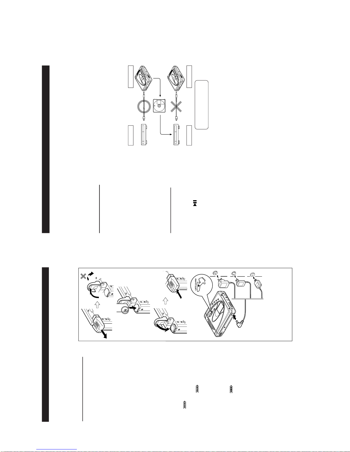
1 High reflection disc MMD-110 (TEAC Test MD) 88GMMD-110
2 Low reflection disc MMD-212 (TEAC Test MD) 74-minute disc 88GMMD-212
3 Low reflection disc MMD-213A (TEAC Test MD) 80-minute disc 88GMMD-213A
4 Low reflection disc Recording minidisc UDSKM0001AFZZ
ADJUSTMENT
Test disc
MD adjustment needs two types of disc, namely recording disc (low reflection disc) and playback-only disc (high
reflection disc).
Type Test disc Parts No.
Note: Use the low reflection disc on which music has been recorded.
EEPROM version
Destination
Leaving the TEST mode
(1) Press the STOP button in the TEST mode stop state.
Test Mode
Microcomputer version
Shipping setting method
Holdingdownsimultaneously theVOLUME-DOWNButton andPLAYButton oftheset unitwithoutdisc, supplythepower fromtheDC INplug.
After the indication "INIT" -> "BYE OK" disappears, release the power supply of DC IN.
1. AUTO 1 Mode • Perform preliminary automatic adjustment.
• If the combination of mechanism and pickup
PWB has been changed, be sure to start from
AUTO1.
2. AUTO 2 Mode
• Perform ATT (attenuator) automatic adjustment.
• Perform continuous playback (error rate display,
jump test)
3. TEST-PLAY Mode
• Continuous playback from the specified address
is performed.
• 1 line, 10 lines or 384 lines manual jump is
performed.
• C1 error rate display (pit section), ADIP error
rate display (groove section)
• The temperature correction is performed only when
servo start is performed, but the posture correction
is not performed during continuous playback.
4. TEST-REC Mode
• Continuous record from the specified address
is performed.
• Change of record laser output(servo gain is also
changed according to laser output).
• The temperature correction is performed only
when servo start is performed, but the posture
correction is not performed during continuous
recording.
5. MANUAL 1 Mode
• Temperature is displayed. (Updating in real time)
• Seeing the displayed adjustment value, perform
preliminary manual adjustment.
(Error rate indication, jump test)
6. MANUAL 2 Mode
• Temperature is displayed. (Updating in real time)
• Seeing the displayed adjustment value perform
manfully the preliminary adjustment.
(Error rate indication, jump test)
• Continuous playback is performed
(error rate display, jump test).
7. RESULT 1 Mode
• The value adjusted in AUTO1 or MANUAL1 is
indicated.
• (Execution in servo "OFF" state").
8. RESULT 2 Mode
• The value adjusted in AUTO 2 or MANUAL 2 is
indicated.
• Adjustment value is changed manually.
(error rate display, jump test).
9. DIGITAL INPUT Mode
• Digital input information is displayed.
10. ERROR INFORMATION
• Error information is displayed.
Mode • Error information is initialized
11. NORMAL Mode
• The mode is changed from the TEST mode to
the normal mode without adjustment.
• In the normal mode the internal operation mode,
memory capacity, etc. areindicated.
• In the normal mode both temperature correction
and posture correction are perfomed.
12. EEPROM Mode
• Factors of digital servo are changed manually.
(Each servo is turned on individually.)
• Cut-off frequency of BASS1, BASS2 and BASS3
is selected manually.
• Temperature detection terminal voltage is
measured, and the reference value is set.
• Defaults are selected and set.
• Setting of EEPROM protect area is updated.
(In case of protect releasing)
13. INNER Mode
• Determine the position where the INNER switch
is turned on. (only high reflection disc).
• The temperature correction is performed only
when servo start is performed, but the posture
correction is not performed.

MD-SR50H/50W/60E/60W
– 11 –
Operation in each TEST mode
1. AUTO1 Mode
• When the STOP button is pressed while the AUTO1 menu appears or during automatic adjustment, the mode changes to the TEST mode
stop state. At this time the adjustment value is not output.
• Be sure to adjust, using the specified disc MMD-213A or MMD-212.
At this time release the EEPROM (IC402) protection. (Refer to EEPROM write procedure.)
• Adjustment NG; Adjustment item out of range, focus ON failure, and adjustment error
• When the PLAY button is pressed while ADJ. OK is displayed, AUTO2 is executed.
2. AUTO2 Mode
• When the STOP button is pressed while the AUTO2 menu appears or during automatic adjustment, the mode changes to the TEST mode
stop state. At this time the adjustment value is not output.
• Adjustment NG; Adjustment item out of range, and adjustment error.
• When the PLAY button is pressed while ADJ. OK is displayed,TEST_PLAY is executed.
3. TEST-PLAY Mode
• When the STOP button is pressed while the TEST-PLAY menu appears, or in TEST-PLAY or continuous playback mode, the mode
changes to the TEST mode stop state.
• When the PLAY button is pressed while the TEST-PLAY menu appears,continuous playback is initiated from the current pickup position.
• Whenever the DISP button is pressed in the TEST-PLAY menu, the target address changes as follows.
0032 — 03C0 — 0700 — 08A0 — 0950— 0032 —
When the PLAY button is pressed while a target address is displayed, continuous playback is performed after searching that address.
• Each time the MODE button is pressed while the TEST-PLAY mode target address is displayed, the digit which is changed by pressing the
SKIP UP/DOWN button is changed as follows.
0032 — 0032 — 0032 — 0032 —
• When the SKIP UP button is pressed in the TEST-PLAY mode target address is displayed, the digit of address specified by the MODE
button is set to +1h. (0 to F)
• When the SKIP DOWN button is pressed in the TEST-PLAY mode target address is displayed, the digit of address specified by the MODE
button is set to -1h. (0 to F)
* When the SKIP UP/DOWN button is held down, the setting changes continuously, one cycle being 100 ms.
• When the BASS button is pressed in the continuous playback mode, the number of jump lines changes as follows.
1 — 10 — 384 — 1
* After the number of jump lines is indicated for one second, the address indication is restored. [ T R _ ]
• When the SKIP UP button is pressed in the continuous playback mode, the specified number of lines is jumped in the FWD direction.
• When the SKIP DOWN button is pressed in the continuous playback mode, the specified number of lines is jumped in the REV direction.
* When the SKIP UP/DOWN button is held down, jump is repeated every approx. 100 ms.
•Whenever the DISP button is pressed in the continuous playback mode, the indication changes as follows.
* Pre-mastered disc
Continuous playback (SUBQ address indication) [ S Q ]
|
Continuous playback (C1 error indication) [ C E ]
|
Continuous playback (SUBQ address indication) [ S Q ]
* Recordabl disk
Continuous playback (ADIP address indication) [ A P ]
|
Continuous playback (C1 error indication) [ C E ]
|
Continuous playback (ADIP error indication) [ A E ]
|
Continuous playback (ADIP address indication) [ A P ]
4. TEST-REC Mode
• When the STOP button is pressed while the TEST-REC menu appears, or in the TEST-REC mode or continuous record mode, the mode
changes to the TEST mode stop state.
• When the PLAY button is pressed while the TEST-REC menu appears, the continuous record is initiated from the current pickup position.
• Whenever the DISP button is pressed in the TEST-REC menu, the target address changes as follows.
0032 — 03C0 — 0700 — 08A0 —0950 — 0032 —
When the PLAY button is pressed while a target address is displayed, continuous playback is performed after searching that address.
• Whenever the MODE button is pressed in the TEST-REC mode target address is displayed, the digit which is changed by the SKIP UP/
DOWN button changes as follows.
0032 — 0032 — 0032 — 0320 —
• When the SKIP UP button s pressed in the TEST-REC mode target address is displayed, the digit of address specified by the BASS button
is set to +1h.(0 to F)
• When the SKIP DOWN button is pressed in the TEST-REC mode target address is displayed, the digit of address specified by the BASS
button is set to -1h. (0 to F)
* When the SKIP UP/DOWN button is held down, the setting changes continuously, one cycle being 100 ms.

MD-SR50H/50W/60E/60W
– 12 –
5. NORMAL Mode
• When the STOP button is pressed while the NORMAL menu appears, the mode changes to the TEST mode stop state.
• Indication during operation
Indication of memory capacity on main unit LCD [ ] + Level meter
: Internal mode
: Address (Cluster section)
: Address (Sector section)
• Selection of sound volume, BASS, etc. is possible (without indication)
• Recording is also possible.
• If the STOP button is pressed during operation in the NORMAL mode, the NORMAL mode is canceled, and the power is turned off.
6. Error data display Mode
• Reversing when SKIP DOWN button is pressed
• When the STOP button is pressed while the error data indication menu appears or during error data indication, the mode changes to the
TEST mode stop state.
• Error data 0 is the latest error.
• Error which occurred in the TEST mode is also stored in the memory.
• When the DISP button is pressed while the error data indication menu appears, the error data is initialized. [ C L E A R _ ]
• : Error Code
Explanation of error history code
12h : RF side FG, TG, and TCRS adjustment termination failure
13h : Adjustment servo retraction excessive retrial
16h : C. IN detection time-over
17h : A, B, E, F, and TCRSO offset measurement value out of
tolerable range
21h : Focus retraction completion allowable time-over
23h : Track search completion allowable time-over
24h : Disc linear speed measurement failure
32h : P-TOC read failure
42h : U-TOC read failure
44h : U-TOC write data write disabled/read check error
52h : SD write data write disabled
71h : Pickup position initialization time-over
72h : EEPROM data read check sum error
73h : Record head drive disabled (by EJECT lever)
82h : Power overvoltage detection
91h : Ambient temperature is higher that the allowable tempera-
ture.
7. INNER Mode
• when the STOP button is pressed on the INNER menu (SQ______ ), the state is changed to the TEST mode STOP state.
• : Address

MD-SR50H/50W/60E/60W
– 13 –
EEPROM (IC402) writing procedure
1. Procedure to replace EEPROM and write initial value of microcomputer in EEPROM
(1) Replace EEPROM.
(2) Refer to the latest EEPROM data list.
(3) Press the Display button, ENTER button and Play button to start the test mode.
(4) Version display
[ V e r . ]
EEPROM version (b ~ Z)
Microcomputer ROM version
(5) The whole LCD lights.
(6) Test mode stop state.
[ T E S T ]
(7) Press the "BASS" button, and press twice the "SKIP DOWN" button.
[ E E P R O M ]
(8) Performtheoperationtodisplay"EEPROMSETTINGMODECHART",comparetheEEPROMDATALISTwiththe display,
and set according to the EEPROM DATA LIST with the VOL UP or VOL DOWN key.
(9) Set the temperature reference. (Refer to the Temperature Reference Setting Method.)
(10)
Set according to the EEPROM DATA LIST.
(11)
Press the Stop button.
[ T E S T ]
(12)
Press the Stop button.
(13)
After data is written in EEPROM, turn off power .
(14)
Restore protection of EEPROM.
2. Temperature reference setting method
[1] Measurement, calculation and setting procedure
(1) Set the TEST mode.
• Set TEST 1, 0 = '01', and turn on power (or set PLAY ON in standby state).
(2) Start the EEPROM mode 'Temp' menu.
• Key operation in order of BASS, SKIP-DOWN x 2 times, PLAY, PLAY in the test mode STOP state.
• 'TM$$%%' is displayed. ($$= Temperature code, %% = Temperature reference)
(3) Once press SKIP-UP, and determine the displayed microcomputer TEMP input AD value.
• 'TPin##' is displayed. (## = TEMP input AD value)
(4) At the ambient temperature, determine the temperature corrected value from the temperature measurement value
correction table.
(5) Determine the temperature reference, using the following formula.
• Temperature reference = Microcomputer TEMP input AD value + Temperature corrected value
(6)Setthetemperaturereferencevaluebybuttonoperation,andcheckwhetherthetemperaturecodeindicationcorrespondsto"Temperature
Code Identification Table".
[2] Temperature measurement value correction table
Ambient
temperature Temperature
correction
+ 9oC ~ +11oC - 05h + 10.0oC
+12oC ~ +14oC - 04h + 12.7oC
+15oC ~ +16oC - 03h + 15.4oC
+17oC ~ +19oC - 02h + 18.2oC
+20oC ~ +22oC - 01h + 20.9oC
+23oC ~ +24oC±00h + 23.6oC
+25oC ~ +27oC + 01h + 26.3oC
+28oC ~ +30oC + 02h + 29.0oC
+31oC ~ +33oC + 03h + 31.8oC
Center
temperature Ambient
temperature Temperature
correction Center
temperature
- 9oC ~ +10oC 08h + 0.5oC
+ 3oC ~ +21oC 07h + 12.5oC
+15oC ~ +33oC 06h + 23.6oC
+26oC ~ +43oC 05h + 35.0oC
X

– 14 –
MD-SR50H/50W/60E/60W
Sled setting Item display Set values
EEPROM DATA LIST (EEPROM version b)
TEMP setting
Item display Set values
T M _ _ Calculate values
ADJ. SET setting
Item display Set values
C O K _ A 0 H
F A T _ C 0 H
T A T _ 3 E H
C A T _ 2 0 H
F A B _ 6 4 H
BASS setting
Item display Set values
B S 1 _ 3 F H
B S 2 _ 1 F H
B S 3 _ E 2 H
S L G _ D F H
S L 2 _ 2 0 H
S L M _ 7 F H
S L V _ A B H
S K k _ 7 2 H
S K t _ 4 C H
S K m _ 7 0 H
W T m _ 2 4 H
M V 1 _ 4 4 H
M V 2 _ 8 8 H
S R V _ 0 0 H
EQ. SET setting
Item display Set values
H Q 1 _ 9 0 H
H Q 2 _ 9 0 H
H S G _ 1 1 H
H S O _ F D H
L Q 1 _ 9 0 H
L Q 2 _ 9 0 H
L S G _ 1 1 H
L S O _ 0 0 H
G Q 1 _ 9 8 H
G Q 2 _ 8 4 H
G S G _ 1 1 H
F L p _ 0 8 H
Control setting
Item display Set values
C T 0 _ 0 1 H
C T 1 _ 1 1 H
C T 2 _ 4 0 H
C T 3 _ 3 0 H
R C 0 _ C 0 H
R C 1 _ F E H
S Y C _ A 6 H
P W L _ 0 1 H
D R 1 _ 0 0 H
D R 2 _ 0 0 H
I N 1 _ C 9 H
I N 2 _ 6 4 H
I N 3 _ 9 9 H
I N H _ 6 4 H
D R H _ 0 C H
P L E _ 1 B H
R C E _ 4 2 H
E L T _ 7 6 H
S L T _ 4 5 H
S P M _ 0 0 H
M S L _ 0 0 H
U S 0 _ 0 0 H
U S 1 _ 0 0 H
U S 2 _ 0 0 H
Item display Set values
F G _ _ B 0 H
F F 1 _ 7 0 H
F F 2 _ E 8 H
F Z H _ E D H
F L n _ 0 A H
D J G _ 1 4 H
F L V _ 2 0 H
W T f _ 2 0 H
F S S _ E 9 H
Fucus setting
Tracking setting
Item display Set values
T G _ _ 4 8 H
T F 1 _ 7 0 H
T F 2 _ E 0 H
T F S _ 0 0 H
T B o _ 4 4 H
T B t _ 2 0 H
T K o _ 4 4 H
T K t _ 1 D H
T D o _ 6 7 H
T D t _ 3 4 H
T G R _ 0 0 H
S C t _ 4 0 H
S C m _ 5 3 H
C L p _ 1 8 H
C L r _ 2 8 H
J P I _ 0 1 H
K 1 0 _ 6 5 H
Item display Set values
S P G _ 1 4 H
S P i _ E 0 H
S P m _ A 0 H
S P o _ 6 8 H
S P 1 _ 1 0 H
S P 2 _ 6 0 H
S P 3 _ F 2 H
S P 4 _ F 2 H
S P 5 _ 1 0 H
S P D _ 6 0 H
S P K _ E B H
Spindle setting

– 15 –
MD-SR50H/50W/60E/60W
: Test Mode STOP
: Pre-auto adjustment menu
: ATT auto adjustment menu
: Continuous record menu
: EEPROM setting menu
: INNER switch position measurement menu
BASS
T E S T
Slide external
periphery move Slide internal
periphery move
Tset Mode Menu
Test Mode Change Chart
A U T O 1
A U T O 2
SKIP UP SKIP DOWN
SKIP DOWN
SKIP UP SKIP DOWN
SKIP UP SKIP DOWN
SKIP UP SKIP DOWN
SKIP UP SKIP DOWN
T R E C
SKIP UP SKIP DOWN
: Continuous playback menu
T P L A Y
SKIP UP SKIP DOWN
SKIP UP SKIP DOWN
SKIP UP SKIP DOWN
: Digital input signal monitor menu
D i n M o n
SKIP UP SKIP DOWN
E E P R O M
SKIP UP SKIP DOWN
I N N E R
SKIP UP
SKIP UP
SKIP DOWN
SKIP DOWN
SKIP UP
* When the [STOP] button is pressed in specific menu, the "TEST MODE STOP" state is set.
* When the [PLAY] button operation is performed in the specific menu, the operation of this
menu is executed.
: Pre-adjustment value check menu
R S L T 1
: ATT adjustment value check menu
R S L T 2
: Pre-manual adjustment menu
M A N U 1
: ATT manual adjustment menu
M A N U 2
: Error history display menu
E D A T A
: Test mode normal playback menu
N O R M A L
: Preautomatic Adjustment menu
: Preadjustment error (adjustment value output)
: During preadjustment adjustment
Adjustment error
Normal end
: Preadjustment normal end (adjustment value output)
: During ATT automatic adjustment
PLAY
PLAY
A U T O 1
Preautomatic Adjustment
A D J . O K
A D J . N G
A T 2
A T 1
* When the [STOP] button is pressed in specific menu, the "TEST MODE STOP" state is set.
* " " represent the adjustment number as follows.
0 0 : Innermost periphery move
0 2 : ABEF offset tentative measurement
0 4 : RF side focus gain coarse adjustment
0 5 : Focus ATT tentative setting
0 6 : RF side bit section tracking gain adjustment
0 7 : COUT level setting for pit section adjustment
0 8 : External periphery move
0 9 : RF side groove section tracking gain adjustment
1 0 : COUT level setting for groove section adjustment
1 1 : RF side TCRS gain adjustment
1 2 : Tracking ATT initial setting
1 3 : RF side focus gain minor adjustment
1 4 : Focus ATT initial setting
1 5 : S gain "High" ABEF offset measurement
1 6 : TCRS offset measurement
1 7 : S gain "Low" ABEF offset measurement

– 16 –
MD-SR50H/50W/60E/60W
: ATT Autoadjustment menu
: ATT adjustment error (adjustment value output)
: During ATT autoadjustment
Adjustment error
Normal end
: ATT adjustment normal end (adjustment value output)
: Continuous playback (high reflection)
: Continuous playback (low reflection)
PLAY
PLAY
A U T O 2
ATT Auto Adjustment
A D J . O K
A D J . N G
S Q # # # #
A P # # # #
A T 2
* When the [STOP] button is pressed in specific menu, the "TEST MODE STOP" state is set.
* " " represent the adjustment number as follows.
0 0 : Innermost periphery move
0 3 : Pit section tracking ATT setting
0 4 : Pit section focus ATT setting
0 6 : External periphery move (low reflection only)
0 7 : TCRS ATT setting (low reflection only)
0 8 : Groove section tracking ATT setting (low reflection only)
0 9 : Groove section focus ATT setting (low reflection only)
: Continuous playback menu
: Continuous playback (pit section)
: Continuous playback (groove section)
# # # # : Address
: Continuous playback (pit section)
: Continuous playback (groove section)
# # # # : Address
PLAY
T P L A Y
Continuous Playback
S Q # # # #
A P # # # #
* When the [STOP] button is pressed in specific menu, the "TEST MODE STOP" state is set.
* In the start address set state the start address changes as follows when the [DISP] button is pressed.
0 0 3 2
H
(initial value) 0 3 C 0
H
0 7 0 0
H
0 8 A 0
H
A d 0 0 3 2 A d 0 3 C 0
DISP
DISP
A d 0 7 0 0
DISP DISP
A d 0 8 A 0
* In the start address setting state the start address change digit changes when the [BASS] button is pressed.
1st digit (initial value) 2nd digit 3rd digit
A d 0 0 3 2 A d 0 0 3 2
MODE
MODE
A d 0 0 3 2
MODE
* In the continuous playback state the number of jump lines changes as follows shown
the [BASS] button is pressed.
1 (initial value) 10 384
1 T R 1 0 T R
BASS
BASS
3 8 4 T R
BASS
• Continuous playback from current pickup position
: Continuous playback menu
: Start address setting
DISP
T P L A Y
A d 0 0 3 2
PLAY
S Q # # # #
A P # # # #
• Continuous playback from any address
* In the start address set state the value of selection digit changes in the range of "0h to Fh"
when the [SKIP UP/DOWN] button is pressed
* When the [SKIP UP] button is pressed in the continued playback mode, jump of specified
number of lines occurs in the external periphery direction.
If the key is held down jump occurs continuously (100 ms cycle).
* When the [SKIP DOWN] button is pressed in the continuous playback mode, jump of
specified number of lines occurs in the internal periphery direction.
If the key is held down, jump occurs continuously (100 ms cycle).
A d 0 9 5 0 H
0 9 5 0
H

– 17 –
MD-SR50H/50W/60E/60W
: Continuous record menu
PLAY
T R E C
Continuous Rrecord
A P # # # #
* When the [STOP] button is pressed in specific menu, the "TEST MODE STOP" state is set.
* In the start address set state the start address changes as follows when the [DISP] button is pressed.
• Continuous record from the current pickup position
: Continuous record menu
: Start address setting
: Continuous record
# # # #: Address
: Continuous record
# # # #: Address
PLAY
T R E C
A d 0 0 3 2
PLAY
A P # # # #
• Continuous record playback from any address
A d 0 0 3 2
0 0 3 2
H
(initial value) 0 3 C 0
H
0 7 0 0
H
0 8 A 0
H
A d 0 3 c 0
DISP
A d 0 7 0 0
DISP DISP
DISP
A d 0 8 A 0
* In the start address setting state the start address change digit changes when the [BASS] button is pressed.
A d 0 0 3 2
1st digit (initial value) 2nd digit 3rd digit
A d 0 0 3 2
MODE
A d 0 0 3 2
MODE
MODE
A d 0 9 5 0
: INNER switch position measurement menu
: Continuous playback (pit section)
# # # # : Address
PLAY
I N N E R
Inner Switch Position Measurement
S Q # # # #
* When the [STOP] button is pressed in specific menu, the "TEST MODE STOP" state is set.
: TEST mode normal playback menu
: Continuous playback
@@@@@@: Mode and address display
PLAY
N O R M A L
Test Mode Normal Playback
@@@@@@
* When the [STOP] button is pressed in specific menu, the "TEST MODE STOP" state is set.
* When the NORMAL mode is canceled, the power is turned off.
: Error history display menu
: Error history 0 display
§ § : Error code
: Error history 1 display
§ § : Error code
: Error history 2 display
§ § : Error code
: Error history 3 display
§ § : Error code
: Error history 4 display
§ § : Error code
: Error history 5 display
§ § : Error code
: Error history 6 display
§ § : Error code
: Error history 7 display
§ § : Error code
: Error history 8 display
§ § : Error code
: Error history 9 display
§ § : Error code
PLAY
E D A T A
Error History Display
E 0 § §
E 1 § §
: Error history display menu
: Error history clear
DISPLAY
E D A T A
C L E A R
SKIP UP SKIP DOWN
E 2 § §
SKIP UP SKIP DOWN
E 3 § §
SKIP UP SKIP DOWN
E 4 § §
SKIP UP SKIP DOWN
E 5 § §
SKIP UP SKIP DOWN
E 6 § §
SKIP UP SKIP DOWN
E 7 § §
SKIP UP SKIP DOWN
E 8 § §
SKIP UP SKIP DOWN
E 9 § §
SKIP UP SKIP DOWN
• Error history clear
• Error history display
* When the [STOP] button is pressed in specific menu, the "TEST MODE STOP" state is set.

– 18 –
MD-SR50H/50W/60E/60W
: EEPROM setting menu
: Focus setting menu
: Spin setting menu
: Tracking setting menu
: Sled setting menu
: BASS setting menu
: TEMP setting menu
: Adjustment setting menu
: Digital EQ setting menu
: Control setting menu
PLAY
E E P R O M
EEPROM Setting
F o c u s
S p i n
SKIP UP SKIP DOWN
T r a c k
SKIP UP SKIP DOWN
S l e d
SKIP UP SKIP DOWN
B a s s
SKIP UP SKIP DOWN
T E M P
SKIP UP SKIP DOWN
A D J S E T
SKIP UP SKIP DOWN
D E Q S E T
SKIP UP SKIP DOWN
C T R L
SKIP UP SKIP DOWN
SKIP UP
SKIP DOWN
* When the [STOP] button is pressed in specific menu, the "TEST MODE STOP" state is set.
* When the [PLAY] button operation is performed in the specific state, the specific setting menu is set.
: BASS setting menu
PLAY
B a s s
BASS Setting
B S 1
B S 2
SKIP UP SKIP DOWN
B S 3
SKIP UP SKIP DOWN
* When the [STOP] button is pressed in specific menu, the "TEST MODE STOP" state is set.
* When the [DISP] button operation is performed in the specific state, the menu changes to
"TEMP SETTING menu".
* In the specific state the setting changes in the range of "00h to FFh" when the
[VOL UP/DOWN] button is pressed.
(The upper limit varies depending on the items)
* When the [MODE] button is pressed in each state, the set digit is changed.
: Focus setting menu
PLAY
F o c u s
Focus Setting
F G
F F 1
SKIP UP SKIP DOWN
F F 2
SKIP UP SKIP DOWN
F Z H
SKIP UP SKIP DOWN
F L n
SKIP UP SKIP DOWN
D J G
SKIP UP SKIP DOWN
SKIP UP SKIP DOWN
F L V
W T f
SKIP UP SKIP DOWN
* When the [STOP] button is pressed in specific menu, the "TEST MODE STOP" state is set.
* When the [DISP] button operation is performed in the specific state, the menu changes to "TEMP SETTING menu".
* In specific state the setting changed in the range of "00h to FFh" when the [VOL UP/DOWN] button is pressed.
(The upper limit varies depending on the items)
* When the [MODE] button is pressed in each state, the set digit is changed.
F S S
SKIP UP SKIP DOWN

– 19 –
MD-SR50H/50W/60E/60W
: Spin setting menu
PLAY
S p i n
Spin Setting
S P G
S P i
SKIP UP SKIP DOWN
S P m
SKIP UP SKIP DOWN
S P o
SKIP UP SKIP DOWN
S P 1
SKIP UP SKIP DOWN
S P 2
SKIP UP SKIP DOWN
S P 3
SKIP UP SKIP DOWN
S P 4
SKIP UP SKIP DOWN
S P 5
SKIP UP SKIP DOWN
S P D
SKIP UP SKIP DOWN
* When the [STOP] button is pressed in specific menu, the "TEST MODE STOP" state is set.
* When the [DISP] button operation is performed in the specific state, the menu changes to
"TEMP SETTING menu".
* In specific state the setting changed in the range of "00h to FFh" when the
[VOL UP/DOWN] button is pressed.
(The upper limit varies depending on the items)
S P K
SKIP UP SKIP DOWN
* When the [MODE] button is pressed in each state, the set digit is changed.
: Tracking setting menu
PLAY
T r a c k
Tracking Setting
T G
T F 1
SKIP UP SKIP DOWN
T F 2
SKIP UP SKIP DOWN
T F S
SKIP UP SKIP DOWN
T B o
SKIP UP SKIP DOWN
T B t
SKIP UP SKIP DOWN
T K o
SKIP UP SKIP DOWN
T K t
SKIP UP SKIP DOWN
T D o
SKIP UP SKIP DOWN
T D t
SKIP UP SKIP DOWN
* When the [STOP] button is pressed in specific menu, the "TEST MODE STOP" state is set.
* When the [DISP] button operation is performed in the specific state, the menu changes to
"TEMP SETTING menu".
* In the specific state the setting changes in the range of "00h to FFh" when the [VOL UP/DOWN]
button is pressed. (The upper limit varies depending on the items)
T G R
SKIP UP SKIP DOWN
S C t
SKIP UP SKIP DOWN
S C m
SKIP UP SKIP DOWN
C L p
SKIP UP SKIP DOWN
C L r
SKIP UP SKIP DOWN
J P I
SKIP UP SKIP DOWN
K 1 0
SKIP UP SKIP DOWN
* When the [MODE] button is pressed in each state, the set digit is changed.

– 20 –
MD-SR50H/50W/60E/60W
: Slide setting menu
PLAY
S l e d
Sled Setting
S L G
S L 2
SKIP UP SKIP DOWN
S L M
SKIP UP SKIP DOWN
S L V
SKIP UP SKIP DOWN
S K k
SKIP UP SKIP DOWN
S K t
SKIP UP SKIP DOWN
S K m
SKIP UP SKIP DOWN
* When the [STOP] button is pressed in specific menu, the "TEST MODE STOP" state is set.
* When the [DISP] button operation is performed in the specific state, the menu changes to
"TEMP SETTING menu".
* In the specific state the setting changes in the range of "00h to FFh" when the
[VOL UP/DOWN] button is pressed.
(The upper limit varies depending on the items)
* When the [MODE] button is pressed in each state, the set digit is changed.
W T m
SKIP UP SKIP DOWN
M V 1
SKIP UP SKIP DOWN
M V 2
SKIP UP SKIP DOWN
S R V
SKIP UP SKIP DOWN
: Temp setting menu
: TEMP reference
: Reference
§ § : Temperature code
: TEMP A/D input value
: Measurement value
PLAY
T e m p
TEMP Setting
T M § §
T p i n
SKIP UP SKIP DOWN
* When the [STOP] button is pressed in specific menu, the "TEST MODE STOP" state is set.
* When the [DISP] button operation is performed in the specific state, the menu changes to
"TEMP SETTING menu".
* In the specific state the setting changes in the range of "00h to FFh" when the
[VOL UP/DOWN] button is pressed.
* When the [MODE] button is pressed in each state, the set digit is changed.
: Adjustment setting menu
PLAY
A D J S E T
Adjustment Setting
C O K
F A T
SKIP UP SKIP DOWN
T A T
SKIP UP SKIP DOWN
C A T
SKIP UP SKIP DOWN
F A B
SKIP UP SKIP DOWN
* When the [STOP] button is pressed in specific menu, the "TEST MODE STOP" state is set.
* When the [DISP] button operation is performed in the specific state, the menu changes to
"TEMP SETTING menu".
* In the specific setting display state the setting change digit changes when the [P-MODE]
button is pressed.
1st digit (initial value) 2nd digit
P-MODE
P-MODE
* In the specific state the setting changes in the range of "0h to Fh" when the [VOL UP/DOWN]
button is pressed.
* When the [MODE] button is pressed in each state, the set digit is changed.
This manual suits for next models
13
Table of contents
Other Sharp Cassette Player manuals

Sharp
Sharp QT-80W User manual

Sharp
Sharp RT-W500H User manual

Sharp
Sharp RD-720H User manual

Sharp
Sharp WQ-T484E User manual

Sharp
Sharp QT-272H User manual

Sharp
Sharp QT-CD44H User manual

Sharp
Sharp JC-202 User manual

Sharp
Sharp WF-1100W User manual

Sharp
Sharp WQ-T484H Quick start guide

Sharp
Sharp QT-CD45H User manual

Sharp
Sharp WF-1000W User manual

Sharp
Sharp WF-1000W User manual

Sharp
Sharp QT-272H User manual

Sharp
Sharp RT-200H User manual

Sharp
Sharp QT-CD80H User manual

Sharp
Sharp SC-700H User manual

Sharp
Sharp QT-250H User manual

Sharp
Sharp QT-80W User manual

Sharp
Sharp QT-90W User manual

Sharp
Sharp VZ-2000 User manual