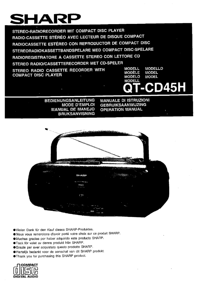
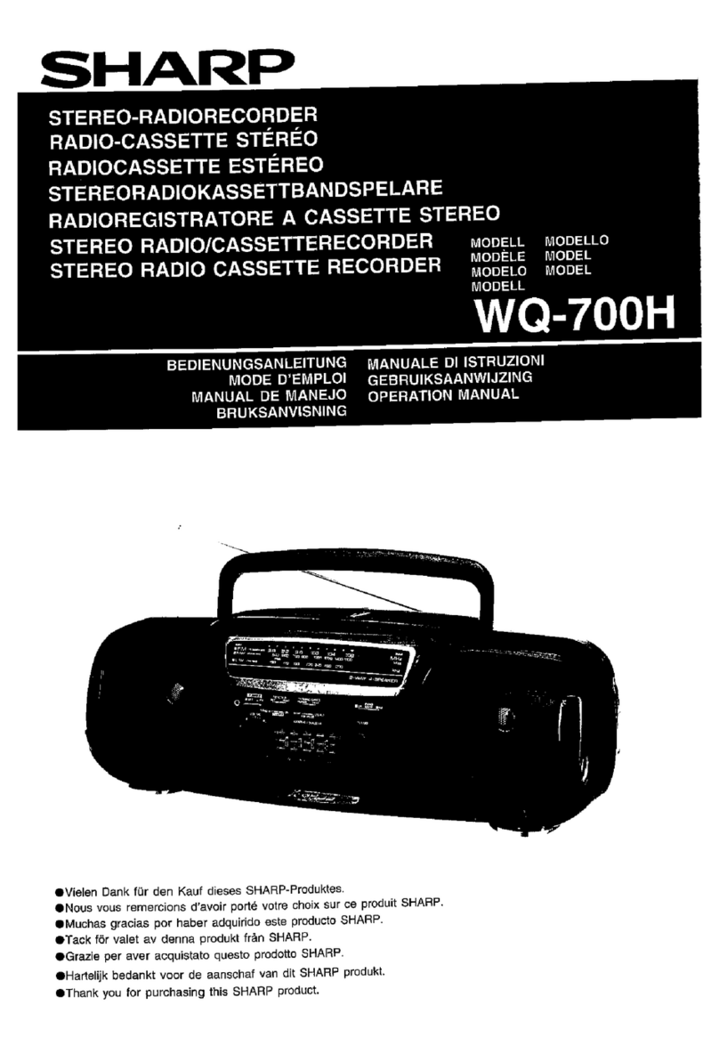
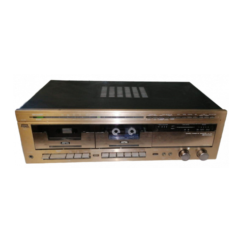
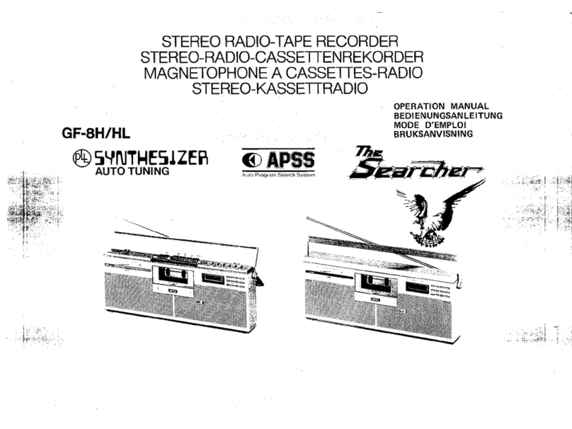
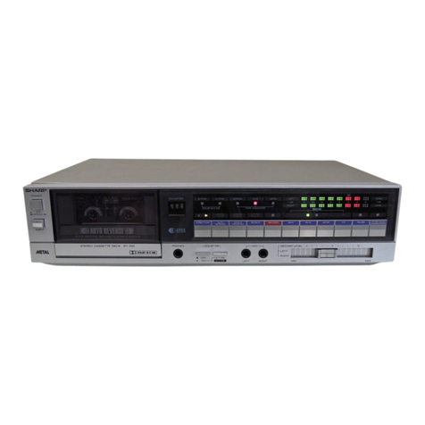
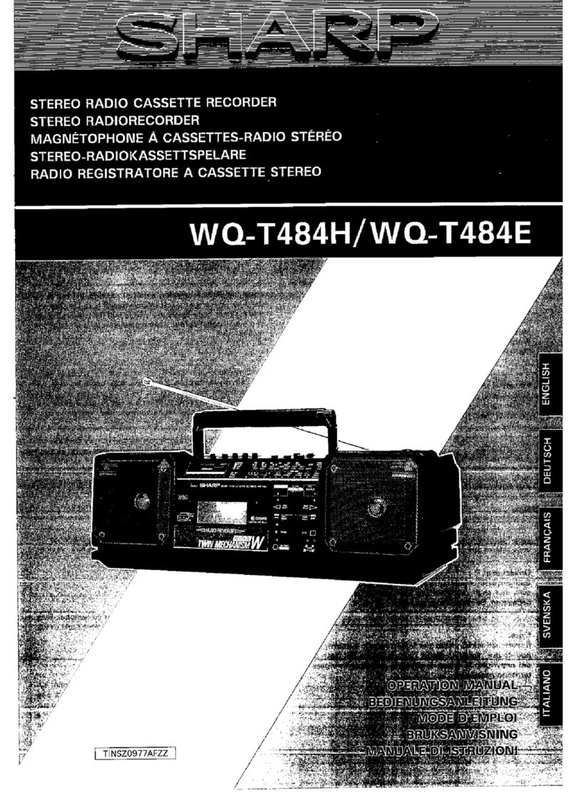
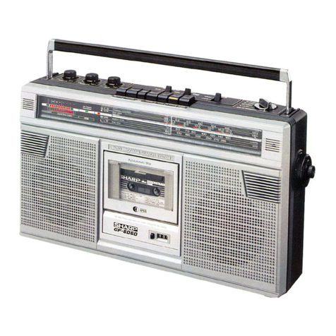
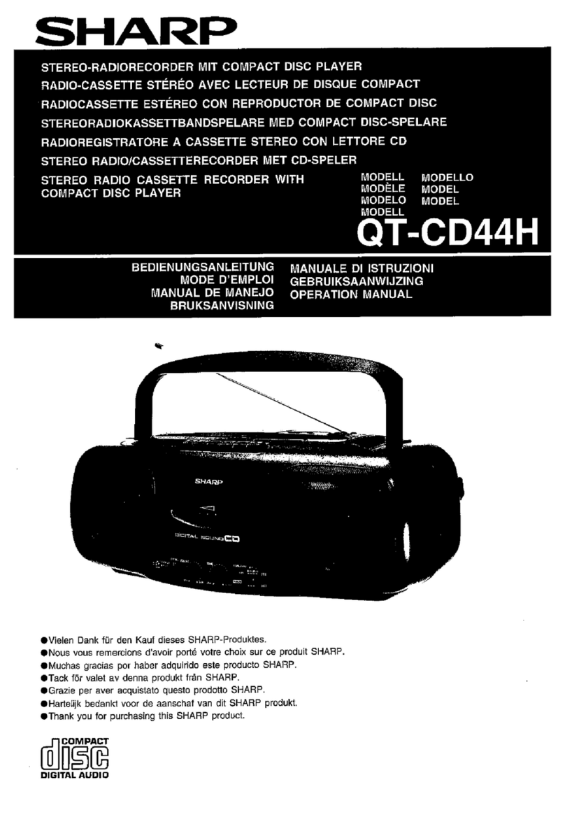
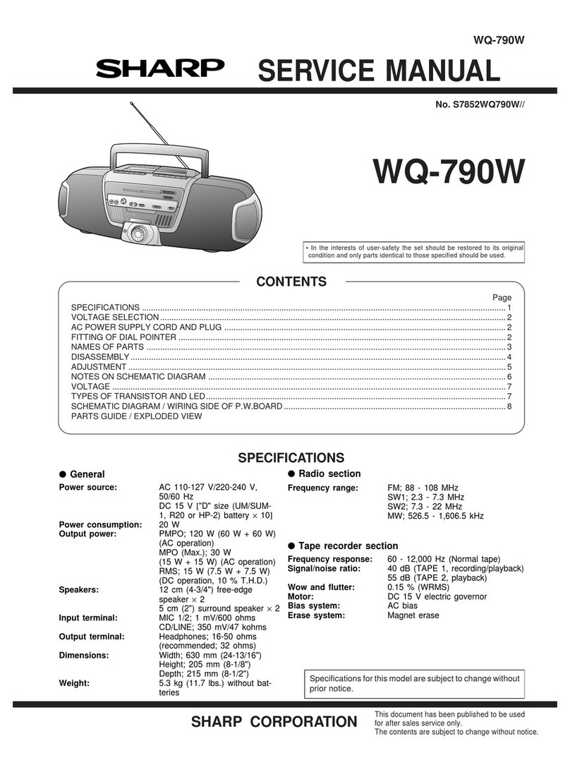
Sharp RT-W500H User manual

SHARP
DOLBY
SYSTEM
@
l
Noise reduction system manufactured under license from Dolby Labora-
tories Licensing Corporation. “Dolby” and the double-D symbol are trade-
marks of Dolby Laboratories Licensing Corporation.
l
Gerluschunterdrtickungssystem
unter Lizenz von Dolby Laboratories Li-
censing
Corporaton
hergestellt.
Das Wort “Dolby” und das Symbol des
doppelten
D
sind die Warenzeichen von
dolby
Laboratories Licensing Cor-
poration.
l
Reducteur de bruits Dolby: Circuit fabrique sous licence des Dolby Labo-
ratories Licensing Corporation.
Le
mot “Dolby” et
le
symbole
double
D
sont
des
marques deposees
des
Dolby Laboratories Licen.$ng Corporatio-
l
In the interests of user-safety the set should be restored to its ori-
ginal condition and only parts identical to those specified be used.
.
Im
lnteresse der
Benutzer-Sicherheit
sollte dieses
Gerlt
wieder
auf
seinen
urspriinglichen
Zustand
eingestellt
und nur die
vorgeschrie-
benen Teile verwendet
werden.
l
Dans
I’interdt
de la
securite
de
I’utilisateur,
I’appareil devra 6tre
reconstitue
dans
sa
condition premiere et seules des pieces
identi-
ques
a
celles specifiees,
doivent
dtre utilisees.
A
INF)E’I
,:;
’
‘“ONTENTS
v.9
:
i[CJ!’
I’,’
.~
SPECIFICATIONS . . . . . . . . . . . . . . . . . . . . . . . . . . . . . . . . . . . . . . . . . .
+
NAMES
OF
PARTS . . . . . . . . . . . . . . . . . . . . . . . . . . . . . . . . . . . . . . . . . . . . .
L-4
Page
WIRING SIDE OF P.W.BOARD . . . . . . . . . . . . . .
.._..........
13,
14
SCHEMATIC
DIAGRAM . . . . . . . . . . . . . . . . . . . . . . . . . . . . . . . . . . . .
15.
16
DISASSEMBLY..
..................................................
5,
6
EQUIVALENT CIRCUIT (BLOCK
BLOCK
DIAGRAM ...................................................
7
DIAGRAM)
OF IC
...............................................
17
CIRCUIT ADJUSTMENT.. .....................................
8,
9
TYPES OF TRANSISTOR AND LED..
........................
17
MECHANICAL ADJUSTMENT ...........................
10,
11
EXPLODED
VIEW
............................................ 18,
19
NOTES ON SCHEMATIC DIAGRAM.. .......................
12
REPLACEMENT
PARTS
LIST.. ..........................
20-24
-
INHALTSVERZEICHNIS
w
Seite Seite
TECHNISCHE
DATEN . . . . . . . . . . . . . . . . . . . . . . . . . . . . . . . . . . . . . . . . . .
2-4
SCHEMATISCHER
SCHALTPLAN . . . . . . . . . . . . . . . . . . . . . . .
15,
16
BEZEICHNUNG
DER
TEILE
. . . . . . . . . . . . . . . . . . . . . . . . . . . . . . . . . . .
2-4
ERSATZSCHALTKREIS
(BLOCK-
ZERLEGEN..
........................................................
5,
6
SCHALTPLAN)
DES
INTEGRIERTEN
BLOCKSCHALTPLAN
...............................................
7
SCHALTKREISES..
..............................................
17
SCHALTUNGSEINSTELLUNG
................................ 8, 9
TRANSISTOREN-UND
LEUCHT-
MECHANISMUSEINSTELLUNG
.......................... IO,
11
DIODENTYPEN..
.................................................
17
ANMERKUNGEN ZUM
EXPLOSIONSDARSTELLUENG
...........................
18,
19
SCHEMATISCHEN
SCHALTPLAN .........................
12
ERSATZTEILLISTE
..........................................
20-24
VERDRAHTUNGSSEITE DER
LEITERPLATTE..
...........................................
13, 14
63
TABLE
DES
MATliRES
w
Page
CARACTERISTIQUES
.......................................... 2-4
NOMENCLATURE..
............................................. 2-4
DEMONTAGE..
....................................................
5,
6
DIAGRAMME SYNOPTIQUE..
....................................
7
RCGLAGE
DU
CIRCUIT..
.......................................
8,
9
RiGLAGE DE
MiCANlSME..
.............................
10,
11
REMARQUES CONCERNANT LE
DIAGRAMME
SCHiMATlQUE..
............................
12
C8TE
CABLAGE
DE LA PLAQUETTE
Page
DE MONTAGE
IMPRIME.. ..............................
13, 14
DIAGRAMME
SCHCMATIQUE
...........................
15, 16
CIRCUITS EQUIVALENTS
(DIAGRAMME
SYNOPTIQUE)
DE
Cl.. .........................................
17
TYPES
DE TRANSISTOR
ET LED.............................
17
vuE
EN
~CLATE
............................................. 18, 19
LISTE
DES PIiCES DE RECHANGE ...................
20-24
SHARP
CORPORATION
0
FOR A COMPLETE DESCRIPTION OF THE OPERATION OF THIS UNIT, PLEASE
REFER TO THE OPERATION MANUAL.
SPECIFICATIONS
Power source: AC 220
V
50/60
Hz
Power consumption: 11
w
Semiconductors: 6
ICs
Dimensions:
Weight:
Tape:
Tape speed:
Wow
&
flutter:
Frequency response:
30 Transistors
22 Diodes
IO
LEDs
Width; 430 mm
(17”)
Height; 124 mm (4-718”)
Depth; 217 mm
(8-g/16”)
3.3 kg (7.3
Ibs.)
Compact cassette tape
4.75
cm/set.
(l-7/8
ips.)
0.1%
(WRMS)
*
0.17% (DIN 45 511)
Normal tape;
40-12,000
Hz (DIN 45 511)
(50-11,000
Hz
*3
dB)
MAXELL UDXL II tape;
30-13,000
Hz (DIN 45 511)
(50-I
2,000 Hz
*3
dB)
TDK Metal tape;
30-
15,000 Hz (DIN 45 51
I)
(50-13,000
Hz
*3
dB)
S/N ratio
(MAXELL
UDXL II tape):
Dolby
NR
off; 52
dB
Dolby
NR
effect; 10
dB
(at over 5
kHz)
Input sensitivity and input impedance:
Microphones; 0.2
mV
(2.2 kohms)
Line In; 50
mV
(50 kohms)
DIN in; 0.2
mV
(2.2.kohms)
Output level and loaded impedance:
Headphones; 0.2
mW
(“0”
dB),
8 ohms
Line Out; 550
mV
(“0”
dBI,
50 kohms
DIN Out; 550
mV
(“0”
dB),
50 koms
Specifications for this model are subject to change without
prior notice.
1. Headphones Jack
2. Deck 2) Digital Tape Counter and Reset Button
j
1
1
?
8
4
?
q
NAMES
OF
PARTS
I I
I
3. Deck 2) Cassette Compartment
I
I I
I
I
I
4.
Deck 1
l
Cassette Compartment
5. Record Level Balance Control
6. Sharpscan Peak Level Display
7. Record Level Control
8. Deck 2) Record Button
9. Deck
2)
Play Button
IO. Deck 2) Rewind Button
11.
Deck 2) Fast Forward Button
12. Deck
2)
Stop/Eject Button
13. Deck 2) Pause Button
14. Deck
1)
Play Button
15. Deck
1)
Rewind Button
16. Deck
1)
Fast Forward Button
17. Deck
1)
Stop/Eject Button
18. Deck
1)
Pause Button
19.
Power Switch
20. Dolby NR Switch
21. Deck 2) Tape Selector Switch
22. Deck
I)
Tape Selector Switch
23. Dubbing Source Selector Switch
24. Dubbing Speed Selector Switch
25. Microphone Jacks
26. Line Output Jacks
27. Line Input Jacks
28. Input Selector Switch
29. DIN Record/Playback Socket
30. AC Power Supply Cord
i3
i
lb 1'1 1'21'3 1'41'51'61'71'8
1'9
/
21iZji4
2'5
20
23
Figure
2-
1
26 28
Figure 2-2
-2-

cc9
EINE
VOLLSTANDIGE
BESCHREIBUNG
DER
BEDIENUNG
DIESES
GERATES
IST
IN DER
BEDIENUNGSANLEITUNG
ENTHALTEN.
TECHNISCHE DATEN
Spannungsversorgung: Netzspannung 220
V
50/60
Hz
Leistungsaufnahme:
II
w
Besttickung: 6 integrierte Schaltkreise
30 Transistoren
22 Dioden
10
Leuchtdioden
Abmessungen: Breite; 430 mm
Hohe;
124 mm
Tiefe; 217 mm
Gewicht: 3,3
kg
Band:
Kompaktcassettenband
Bandgeschwindigkeit:
4,75
cm/s
Gleichlaufschwankungen: 0.1%
(WRMS)
Frequenzgang:
f
0.17% (DIN 45
5111
Normalband;
40-12
000 Hz (DIN 45 511)
(50-I
1 000 Hz
*3
dBi
MAXELL UDXL II -Band;
30-
13 000 Hz (DIN 45 51
I)
(50-
12 000 Hz
*3
dB)
TDK-Reineisenband;
30-
15 000 Hz
IDIN
45 51
I)
(50-13
000 Hz
A.3
dB)
Rauschabstand
(MAXELL
UDXL II
-Band):
Dolby-NR ausgeschaltet; 52
dB
Dolby-NR-Effekt;
10
dB
lbei uber
5
kHz)
Eingangsempfindiichkeit und impedanz:
Mikrofoneingang; 0,2
mV
(2,2
k0hmi
Direkteingang; 50
mV
(50 k0hm)
DIN-Eingang; 0,2
mV
(2,2 kOhml
Ausgangspegel und Belastungsimpedanz:
Kopfhlirerausgang;
0,2
mW
(“0”
dB),
8 Ohm
Direktausgang; 550
mV
(“0”
dBI,
50
kOhm
DIN-Ausgang; 550
mV
(“0”
dB),
50
kOhm
Die technischen Daten
fur
dieses
Model1
kijnnen ohne
vor-
herige Ankiindigung Anderungen unterworfen sein.
BEZEICHNUNG
DER
TEILE
1.
Kopfhorerbuchse
2. Deck 2) Digitales Bandzahlwerk und
Rtickstelltaste
3. Deck
2)
Cassettenfach
4. Deck
I)
Cassettenfach
5.
Aufnahmepegel-Balancesteller
6.
Sharpscan-Spitzenwertanzeigefeld
7.
Aufnahmepegelsteller
8. Deck
2)
Aufnahmetaste
9. Deck
2)
Wiedergabetaste
10. Deck 2) Rtickspultaste
11.
Deck 2) Schnellvorlauftaste
12. Deck 2)
Stopp-/Auswurftaste
13. Deck 2) Pausentaste
14.
Deck
1
l
Wiedergabetaste
15. Deck
1)
Rtickspultaste
16. Deck
I)
Schnellvortauftaste
17. Deck
1)
Stopp-IAuswurftaste
18. Deck
I)
Pausentaste
19.
Netzschalter
20. Dolby-NR-Schalter
2
I.
Deck 2) Bandsortenwahlschalter
22. Deck
1)
Bandsortenwahlschalter
23. Uberspielquellen- Wahlschalter
24. Uberspielgeschwindigkeits- Wahlschalter
25. Mikrofonbuchsen
26. Direktausgangsbuchsen
27. Direkteingangsbuchsen
28. Eingangswahlschalter
29. DIN-Anschlul3
fur
Aufnahmewiedergabe
30. Netzkabel
-3-

ZERLEGEN
Vorsichtsmassregeln Fiir Das Zerlegen Prhcautions pour
le
dhmontage
Beim Zerlegen und Zusammenbauen des GerMes die folgen-
Lors du demontage de I’appareil et de son remontage, sui-
den Anweisungen befolgen,
urn
dessen Betriebssicherheit vre
les
pr6cautions ci-dessous, pour maintenir la s6curit6
und ausgezeichnete Leistung aufrechtzuerhalten. et d’excellentes performances.
1.
Cassette
aus
dem cassettenhalter entfernen.
1.
Deposer la bande cassette du Porte-cassette.
2. Bevor mit dem Zerlegen des
Ger&ites
begonnen wird,
un-
2. S’assurer de retirer la fiche d’alimentation secteur de la
bedingt den Netzkabelstecker
aus
der Netzsteckdose prise murale avant de d6marrer
le
dbmontage de
ziehen. I’appareil.
3. Nylonbsnder oder Leitungshalter entfernen, fails dies
beim Zerlegen des Gertites erforderlich ist.
Nach
Warten
des Gergtes darauf achten, die Leitungen wieder so zu
verlegen, wie sie vor den Zerlegen angeordnet waren.
4. Beim Ausftihren von Wartungsarbeiten auf statische
Elek-
trizitM
der integrierten Schaltkreise und anderen
Schal-
tungen achten.
3.
DBposer
les
bandes de nylon ou
les
serre-cgbles
si
n&es-
saire lors du demontage de I’appareil.
Apr&
la rkpara-
tion de I’appareil, s’assurer de redisposer
les
fils tel qu’ils
Btaient avant
le
dbmontage.
4. Faire attention
&
I’Blectricit6 statique des circuits
integr&s
et des autres circuits lors de la rkparation.
SCH-
RITT
1
2
Frontolatte
3
Laufwerkblock
4LED
leiterplatte
1
I.
Schraube . . . . . . . . . . . . . . . . . . . .
lH)x2
1
5
6
7
ENTFERNEN
VERFAHRENABBIL-
DUNG
Gehluse
1.
Schraube..
.................. (A)xE
I.
Schraube .................... (B)x7
2.
Kabel..........................
(C)xl
3.
Buchse..
..................... (Dlx?
4.
Aufnahme-Mliedergabe
Wahlschalterstab..
........
(E)xl
1. Schraube.....................
(F)xe
2.
Bandzdhlwerk-
Antriebsriemen ............
(G)xl
Aufnahmepegel-
stellerleiterplatte
und
Aufnahmepegel-
Balancesteller
leiterplatte
5-l
5-2 5-3
5-3
5-4
5-3
1. Schraube .....................
(11x3
2. Kragstein.. ...................
(J)xl
3.
Knopf
.........................
(K)xl
I-
5-2
KopfhBrerstecker-
I.
Schraube . . . . . . . . . . . . . . . . .
(L)xl
5-3
leiterplatte
Hauptleiterplatte
1.
Schraube..
..................
(M)x4
2.
Buchse
....................... (Nix1
0
DiMONTAGE
ETA-
PE
1
2
DEPOSE
PROCcDi:
FIGURE
3
4
5
Coffret
I.
Vis.. ...........................
(A)x5
5-l
Panneau avant
I.
Vis ............................. (B)x7 5-2,
5-:
2.
Cdblage..
....................
(C)xl
5-3
3.
Douille..
...................... 10)x3 5-4
4. Tige de
&lection
enregistre-
5-3
ment/lecture..
..............
(E)xl
Bloc du
1.
Vis ............................. (F)x6
m&canisme 2. Courroie d’entrainement du
compteur
de bande ......
IG)xl
PMI LED
1.
Vis..
...........................
IH)x2
PMI control de
1.
Vis
..............................
(1)x3
niveau
d’enregis-
2.
Consale..
.....................
(J)xl
trement et PMI 3.
Bouton
.......................
(K)xl
5-2
commande de
balance due
niveau
d’enregis-
trement
6PMI jack de
casque
7
PMI principale
1. Vis .............................
(L)xl
5-3
I.
Vis ............................
(M)x4 5-1,
5-r
2.
Douilie..
......................
(N)xl
5-4
-6-

DISASSEMBLY
Caution on Disassembly
Follow the below-mentioned notes when disassembling the
unit and reassembling it, to keep its safety and excellent
performance:
1. Take cassette tape out of the cassette holder.
2. Be sure to remove the power supply plug from the wall
outlet
before starting to disassemble the unit.
3. Take off nylon bands or wire holders where they need
be removed when disassembling the unit. After servic-
ing the unit, be sure to rearrange the leads where they
were before disassembling.
4. Take sufficient care on static electricity of integrated cir-
cuits and other circuits when servicing.
ZTEP
REMOVAL
PROCEDURE FIGURE
1
(Cabinet
/
1. Screw . . . . . . . . . . . . . . . . . . . . . . . .
lA1x5/
5-l
2Front Panel
1.
Screw.. .......................
IB)x7
2. Lead...........................
(C)xl
3. Socket........................ (D)x3
4. Record/playback selector
rod ...........................
(E)xl
3Mechanism Block
I.
Screw.. ....................... (F)x6
2. Tape counter drive
belt.. ........................
(G)xl
4LED P.W.B.
1.
Screw.. ...................... (H)xZ
5
Record Level Con-
1.
Screw . . . . . . . . . . . . . . . . . . . . . . . . . .
(11x3
trol
P.W.B. and 2. Bracket
.,............,........
(J)xl
Record Level
3. Knob . . . . . . . . . . . . . . . . . . . . . . . . .
(K)xl
Balance Control
P.W.B.
7
5-2
6Headphones Jack
1.
Screw.. .......................
(L)xl
5-3
P.W.B.
7Main P.W.B. 1. Screw........................
(M)x4
5-1, 5-4
2. Socket.. ......................
(N)xl
5-4
1
T-
(B)
x
3
(8)
x
1
$3
x
8mm
43
x
8mm
Fran:
Panel
(B)
x’l
43
x
8mm
Figure 5-2
63)
x
1
x
43
8mm
(1)
2
r
43
x8mm
LED P.W.B.
Record Level
I
Balance Control P.W.B.
Record Level
Control
P.W.B.1
(B)
x
1
(F)
x
i
43
x
IOmm,
43
x
8mm,
Red Black Headphone Jack
(F)
i
5 P.W.B.
43
x
IOmm,
Red
Figure 5-3
(A)
x
2
44
x
8mm
(Ml
x
1
,43
x
8mm
44
x
8mm
Figure
5-
1 Figure
5-4
-5-

POUR LA DESCRIPTION COMPLETE DU FONCTIONNEMENT DE CET APPAREIL,
SE REPORTER AU MODE D’EMPLOI.
CARACTiRlSTlQUES
Alimentation: 220
V
CA,
50/60
Hz
Consommation: 11
w
Semi-conducteurs: 6 Cl
30 transistors
22 diodes
10
LED
Dimensions:
Largeur;
430 mm
Hauteur; 124 mm
Profondeur;217 mm
Poids:
3,3
kg
Bande:
Cassette compacte
Vitesse de defilement:
4,75
cm/s
Pleurage et scintillement:
0,l
%
(WRMS)
f
0,17%
(DIN 45 511)
Reponse
en frequence: Bande normale;
40
$I
12 000 Hz (DIN 45 511)
(50
B
11
000 Hz
*3
dB)
Bande MAXELL UDXL
II
;
3Oa
13000Hz(DIN45511)
(50
B
12 000 Hz
*3
dB)
Bande metallique TDK;
30
B
15 000 Hz (DIN 45
51
I)
(50
i
13 000 Hz
*3
dB)
Rapport S/B: (bande MAXELL UDXL II
)
Dolby NR hors circuit; 52
dB
Effet Dolby NR;
10
dB
(2
plus de 5
kHz)
Sensibilite d’entree et impedance d’entree:
Microphones; 0,2
mV
(2,2
kohms)
Niveau de sortie et
impedance chargee:
Entree de ligne; 50
mV
(50
kohms)
Entree DIN;
0,2
mV
(2,2
kohms)
Casque;
0,2
mW
(“0”
dB),
8 ohms
Sortie de ligne; 550
mV
(“0”
dB),
50 kohms
Sortie DIN; 550
mV
(“0”
dB),
50 koms
Les caracteristiques de ce modele sont sujettes
a
modifica-
tion
sans
preavis.
NOMENCLATURE
1.
Douille de
casque
2. Platine 2) Compteur numerique de bande et bouton de
remise
a
zero
3. Platine 2) Compartiment de cassette
4. Platine
1)
Compartiment de cassette
5. Commande de balance de niveau d’enregistrement
6. Afficharge de niveau de
c&e
Sharpscan
7. Commande de niveau d’enregistrement
8. Platine 2)
Bouton
d’enregistrement
9. Platine
2)
Bouton
de lecture
IO. Platine 2) Bouton de rebobinage
11.
Platine 2)
Bouton
d’avance rapide
12. Platine
2)
Bouton
d’arretiejection
13. Platine 2)
Bouton
de pause
14. Platine
1)
Bouton
de lecture
15. Platine
1)
Bouton
de rebobinage
16. Platine
1)
Bouton
d’avance rapide
17. Piatine
1)
Bouton
d’arretlejection
18. Piatine
1)
Bouton
de pause
19.
Commutateur d’alimentation
20. Commutateur Dolby NR
21. Platine 2) Commutateurs de selection de bande
22. Platine
1)
Commutateur de selection de bande
23. Commutateur de selection de source de copie
24. Commutateur de selection de vitesse de copie
25. Douilles de microphone
26. Douilles de sortie de ligne
27. Douilles d’entree de ligne
28. Commutateur de selection d’entree
29. Douille
d’enregistrement/lecture
DIN
30.
Cordon d’alimentation
-4-

-s.t
I-
ll
Figure 7 BLOCK DIAGRAM

CIRCUIT
ADJUSTMENT
TPlOl
or
TP201
[;mrd
Modeprk
/Ej
SETTING
POSITION
OF SWITCH
AND KNOB
ITEM
BIAS
OSCILLATOF
FREQUENCY
Dolby
NR
Switch: off
Dubbing Speed Selector Switch: Normal
Deck 1 Tape Selector Switch: Normal
Deck 2 Tape Selector Switch: Normal
Dubbing Source Selector Switch: Line
Frequency
Counter
--L-=-l
I
GND
Figure
8-
1 BIAS OSCILLATOR FREQUENCY
INPUT
REMARKS
(CHECK1
ADJUST-
MENT
POINTS
L301
L: VR301
R:
VR302
-
Test tape L: VR104
MTT-150
R:
VR204
Test tape
MTT-150
-
Non-recorded
tape
(MTT-502)
1 kHz,
-13 dBV
(-3
dB
REC)
L: VR103
R:
VR203
105
i5
kHz Record Mode TP301 Erase
BIAS
CURRENT
Normal: 13 V
croz:
19
v
Metal: 30 V
Figure 8-2 ERASE CURRENT
Electronic
Voltmeter
Record Mode
R305
(L-ch)
or
R306
0%ch)
Figure 8-3 BIAS CURRENT
Electronic
ERASE
CURRENT
Metal: 36
_+4
V
Normal: 540 mV
DECK 1
PLAYBACK
SENSITIVITY
DECK 2
PLAYBACK
SENSITIVITY
See that the electronic
voltmeter reading is
within the range from
481 mV to 606 mV.
If not, take the proce-
dures shown in the
Table
l
1.
RECORD/
PLAYBACK
SENSITIVITY
1.
Adjust the record
level knobs so that
the electronic volt-
meter reads 380
mV.
2. Playback the normal
tape recorded and
adjust the semi-
variable resistor so
that the electronic
volt-meter read 380
mV.
Voltmeter
LINE
Playback Mode QUT
1
m
Unit
0
0
GND
Test
MTT
/
Figure 8-4 DECK l/DECK 2 PLAYBACK SENSITIVITY
LINE
L
Low Frequency
Oscillator
iN
/
rd
Mode
Table
*I
Voltmeter reads
More than 606 mV
Less than 481 mV
Procedures
Cut the resistor
Rl
11, R211
Cut the resistor
R109,
R209
,
--6’
LINE
Electronic OUT Playback
.
-
ze
I
Non
-recorded
Tape
MTT-502
Figure 8-5 RECORD/PLAYBACK SENSITIVITY
-8-

0
RiGLAGE
DU
CIRCUIT
@SCHALTUNGSEINSTELLUNG
F
1
L
E
1
SCHALTER-
UND
STELLER-
EINSTELLPO-
SITION
IkGLAGE DE
.A POSITION
)ES
COMMU-
‘ATEURS ET
)ES
lOUTONS
ARTICLE
1
Dolby-NR-Schalter:
Aus
1
U
berspielgeschwindigkeit: Normal
1
Deck 1 Bandsortenwahlschalter: Normal
1
Deck 2 Bandsortenwahlschalter: Normal
1
ljberspielgeschwindigkeits-Wahlschalter:
Eingang
1
Commutateur
Doly
NR: Coupe
1
Commutateur de selection
vitesse
de copie:
Normale
1
Commutateur de selection de bande 1: Normal
)
Commutateur de selection de bande 2: Normal
1
Commutateur de selection de source de
copie:
I:
E
BENNENNUNG EINGANG
.INSTELL-
PUNKT
BEMERKUNGEN
(PRUFUNG)
Ligne
ENTREE
‘OINT DE
IliGLAGE REMARQUES
(VtRIFICATION)
VORMAGNETI-
SIERUNGSSC-
HWING
FREQUENZ
.301 105
25
kHz REQUENCE
)E
L’OSCILLA-
-ION DE
‘OLARI-
;ATION
301 105
?5
kHz
E
I:
1
F
E
(
F
I
(
I
(
!
1
F
:
I
I
F
<
I
I
VORMAGNETISIE-
RUNGSSTROM
VR301
,.
1:
VR302 Vormalband: 13 V
3rOz
-
Band: 19
V
3eineisenband: 30 Vi:
Vi=!301
):
VR302 \lormal: 13 V
ZrOz:
19 V
Vletal:
30 V
netal:
36
+4
V
:OURANT
DE
‘OLARI-
SATION
:OURANT
I’EFFA-
:EMENT
-
LQSCHSTROM
-
qeineisenband:
36
f4V
Normalband: 540 mV
-
VR104
i:
VR204
-
Testband
vlTT-
150
WIEDERGABE-
EMPFINDLICH-
KEIT
VON
DECK 1 ;ENSlBlLlTi DE
.ECTURE
DE
LI
‘LATINE 1
3ande d’essai
VITT-150 ;: VR104
):
VR204 Vormal: 540 mV
WIEDERGABE-
EMPFINDLICH-
KEIT
VON
DECK 2
Testband
VITT-150
oberpriifen,
ob der
elektronische
Spannungsmesser
481 mV bis 606 mV
anzeigt.
Wenn es
nicht
so ist,
die
Nachsteilung
gem%
Tabelle *1
vornehmen.
1. Den
Aufnahmepe-
gelsteller so
einstel-
len,
da5
der
elektronische Span-
nungsmesser
380
mV
anzeight.
2. Das bespielte Nor-
malband
wiederge-
ben und den
Trimmer so einstee-
len. da5 der
elektro-
nische
Spannungsmesser
380 mV anzeigt.
-
_:
VR103
3:
VR203
;ENSlBlLlTi
3E
LECTURE
)E
LA
‘LATINE
2
3and d’essai
UT-11 50 r/air si I’indication du
u’oltmetre
electronique
se situe entre 481 mV
?t
606 mV.
Sinon,
effectuer
les
xocedes
indiques dam
e
Tableau *1.
SENSIBILITE
I’ENREGIS-
TREMENTI
SECTURE
3ande non
snregistree
MTT-502
1 kHz,
-13 dBV
(-3
dB
REC)
;:
VR103
1:
VR203
1.
Regler la
bouton
de
commande de
niveau du disque
dt
telle sorte que
le
voltmetre
electroni-
que indique 380
mV.
2. Lire une bande nor-
male enregistree et
regler la resistance
semi-variable de
telle sorte que
le
voltmetre
electroni-
que indique 380
mV.
AUFNAHME-I
WIEDERGABE-
EMPFINDLICH-
KEIT
Jnbespieltes
3and
MTT-502
1 kHz,
-13 dBV
;-3
dB
REC)
i
Tableau
*I
Tabelie
*I
Den Widerstand
R109
oder
R209
-9-

0
MECHANICAL
ADJUSTMENT
Dual-trace
Electronic Oscilloscope
Head
Figure IO- 1 AZIMUTH
A
S
Small as Possible
ic
ITEM ADJUSTMEN
POINTS
IT
7
-I-
~
d
1
USING JIG
Tape
tention
measuring
cassette
TW-2412
REMARKS
(CHECK)
lriving
lower
(More than
140
g)
-est
/ITT
rorque Torque meter
Play
TW-2111
Fast-forward
TW-2231
Rewind
TW-2231
-
(Play:
30-60
g-cm1
(Fast-forward:
55-l 10 g-cm)
(Rewind:
55-
110
g-cm)
Test tape
MTT-114
izimuth
adjusting
screw
Sine waveform
attains the maximur
izimuth
rape speed Test tape
High speed
MTT-111
Normal
speed
MTT-111
High speed
Deck
1:
6,000
T,“,”
k
Deck 2: 6,000
+2Ok
-40
Normal speed
Deck
1:
3,000
I:,”
t
Deck 2: 3,000
ilOk
-20
l
Perform the high
speed adjustment
first and then the
normal speed ad-
justment.
iigh
speed
Ieck
1: VR401
Ieck
2:
VR40:
dormal
speed
leek
1:
VR40;
leek
2: VR40L
’
Short
TPI
an
ground when
performing
tt
high speed
as
justment.
Figure
10-2
AZIMUTH WAVEFORM
Record/Playback
Test Tape
MTT-111
j-0
GND I
Figure 1 O-3 TAPE SPEED
1
MAIN
PWB-AI
1
LINE
DIN
IN
RECORD/PLAYBACK
-
1
Deck 2 Speed
I
HIGH
SPEEDTPl
DR-ch
VR204
(f
I
(GNDI
ERASE CURRENT
fTP201)
IGND)
BIAS CURRENT
ITPIOII
CNS I
1
I
Figure
IO-4
ADJUSTMENT POINTS
-lO-

@
MECHANISCHE
EINSTELLUNG
0
BENEN- FUHRUNG-
EINSTELL-PUNKT BEMERKUNGEN
NUNG
SLEHRE
(PRijFUNG)
Antriebs-
Bandzug- (Mehr
als
140
g)
kraft Mel&cassette
-
TW-2412
Dreh-
moment
Drehmoment-
messer
Wiedergabe:
TW-2111
Schnellvorlauf:
TW-2231
Rtickspulung:
TW-2231
(Wiedergabe:
30
-
60 g-cm)
(Schnellvorlauf:
-
55
-
110 g-cm)
(Rtickspulung:
55
-
110 g-cm)
Azimut
Testband
MTT-114 Azimuteinstell-
schraube Sinuswellenform
wird maximal.
Bandge-
schwin-
digkeit
Testband
Hohe
Geschwin-
Hohe
Geschwin-
Hohe digkeit digkeit
Geschwindig- Deck 1: VR401 Deck 1:
keit Deck 2: VR403 6000
‘2”o”
Hz
MTT-111 Normal Deck 2:
Normale Geschwindigkeit
Geschwindig- Deck
1:
VR402 6000
‘ii
Hz
keit Deck 2: VR404 Normal
Geschwin-
MTT-111 *
Bei
der Einstel- digkeit
lung der hohen Deck 1:
3000
:f,”
Hz
Geschwindigkeit Deck 2:
TPI
und Erde
kurzschlief3en. 3000
‘;,”
Hz
l
Zuerst die hohe,
dann die norma-
le
Geschwindig-
keit einstellen.
ARTICLE
‘uissance
l’entrai-
iement
:ouole
Azimuth
Jitesse de
a bande
RiGLAGE
MECANIQUE
GABARIT
Cassette de
mesure de
tension de la
bande
TW-2412
Compteur de
couple
Lecture:
TW-2111
Avance
rapide:
TW-2231
Rebobinage:
TW-2231
Bande
d’essai
MTT-114
Bande
d’essai
Grande
Vitesse:
MTT-111
Vitesse
normale:
MTT-111
POINTS DE
RtkGLAGE
REMARQUES
IV~RIFICATION)
-
/is
de reglage de
‘azimuth
jrande
vitesse
‘latine
1:
VR401
‘latine
2: VR403
litesse
normale
‘latine
1: VR402
‘latine
2: VR404
’Mettre la platine
TPI
a
la terre
lors du reglage
a
vitesse
Blevee.
(Plus de 140 g)
(Lecture:
30
A
60 g-cm)
(Avance
rapide:
55
a
110 g-cm)
(Rebobinage:
55
a
110 g-cm)
La
forme
d’onde
sinuso’idale atteint
le
maximum.
Grande vitesse
Platine 1:
6000
1;;
Hz
Platine 2:
6000
‘j;
Hz
Vitesse
normale
Platine
1:
3000
‘f,”
Hz
Platine 2:
3000
-20
+‘O
Hz
*
Effectuer
d’abord
le
reglage de la
grande
vitesse
et
ensuite
celui
de la
vitesse
normal.

7
0
NOTES
ON
SCHEMATIC
DIAGRAM
. Resistor:
To differentiate the units of resistors, such symbol as
K
and
M
are used: the symbol
K
means 1000 ohm and the sym-
bol
M
means 1000 kohm and the resistor without any sym-
bol is ohm-type resistor. Besides, the one with “Fusible”
is a fuse type.
l
Capacitor:
To indicate the unit of capacitor, a symbol
P
is used: this
symbol
P
means micro-micro-farad and the unit of the capa-
citor without such a symbol is microfarad. As to electrolyt-
ic capacitor, the expression “capacitance/withstand
voltage” is used.
(ML): Mylar type
(P.P.1:
Polypropylene type
l
The indicated voltage in each section is the one measured
by Digital Multimeter between such a section and the chas-
sis with no signal given.
. Schematic diagram and Wiring Side of
P.W.Board
for this
model are subject to change for improvement without prior
notice.
l
Parts marked with
“A”
(
,.
1
are important for maintain-
ing the safety of the set. Be sure to replace these parts with
specified ones for maintaining the safety and performance
of the set.
/
03
ANMERKUNGEN
ZUM
SCHEMATISCHEN SCHALTPLAN
Widerstande:
Urn
die Einheiten der Widerstande unter-scheiden
zu
ken-
nen, werden Symbole Wir
K
und
M
benutzt. Das Symbol
K
bedeutet 1000 Ohm und das Symbol
M
1
000 Kiloohm;
Bei
Widerstanden ohne Symbol handelt es
sich
urn
ohmsche
Widerstande. AuBerdem sind die mit “Fusible”
bezeichne-
ten Widerstdnde Schmelzsicherungstypen.
Kondensatoren:
Zum
Bezeichnen der Kondensatore.inheit wird das Symbol
P
benutzt; dieses Symbol
P
bedeutet Nenofard. Die Einheit
eines Kondensators ohne Symbol ist Mikrofarad. Fijr
Elek-
trolytkondensatoren wird die Be-zeichnung
“Kapazitltl
Stehspannung” benutzt.
(ML): Mylarkondensator
(P.P.):
Polypropylentyp
l
Die in den einzelnen Teilen angegebenen Spannungen wer-
den mit einem DigitalvielfachmeRgerbt zwischen dem
be-
treffen den Teil und dem Chassis ohne Signalzuleitung
gemessen.
l
Anderungen des schematischen Schaltplans und der Ver-
drahtungsseite der Leiterplatte
fiir
dieses
Model1
im Sinne
von Verbesserungen jederzeit vorbehalten.
.Die mit
B
(
2L
‘Z.)
bezeichneten Teile sind besonders
wich-
tig
ftir
die Aufrechterhaltung der Sicherheit. Beim
Wechsein
dieser Teile sollten die vorgeschriebenen Teile immer ver-
wendet werden,
urn
sowohl die Sicherherheit
als
such
die
Leistung des Gerates aufrechtzuerhalten.
0
REMARQUES CONCERNANT
LE
DIAGRAMME
SCHEMATIQUE
l
RBsistance:
Pour
differencier
les
unites de resistances, on utilise des
symbole tels que
K
et M:
le
symbole
K
signifie 1000 ohms,
le
symbole
M
1000 Kohms, et la resistance
donnee
sans
symbole est une resistance de type ohm. En outre,
celle
qui
est dotees de “Fusible” est de type
a
fusible.
.
Condensateur:
Pour indiquer I’unite de condensateur, on utilise
le
symbole
P; ce symbole
P
signifie micro-microfarad, et
I’unite
de
con-
densateur
donnee
sans ce symbole est
le
microfarad. En ce
qui concerne
le
condensateur Blectrolytique, on utilise
I’expression “tension de
regimelcapacite”.
(ML): Condensateur Mylar
(P.P.):
Type Polypropylene
l
La tension
indiquee
dans chaque section est celle
mesuree
par un multimetre numerique entre la section en question
et
le
chassis, en I’absence de tout signal.
l
Le diagramme schematique et
le
cot6
cdblage
de la
PMI
de
ce
modeie
sont sujets
a
modifications sans preavis pour
I’amelioration de ce produit.
l
Les pieces portant la marque
d
(
“”
1
sont particulierement
importantes pour
le
maintien de la securite. S’assurer de
les
remplacer par des pieces du
numero
de piece specific pour
maintenir la securite et la performance de I’appareil.
-12-
_-I-
-------+-Me1
-.----

1
2
3
I
4
5
6
.ylu
0
.j
g(-
“RIO,
r
-----
-----,----------
I
I
.‘.
rl
I
i
,:,
L-d
r;
I
R-e
I
L-----L-..-~L--_~2..J
RECORD LEVEL CONTROL
PWB-A4
0610 0609
0606
LED
PWB-A2
1
234
5
6
-13-
Figure 13 WIRING
SIDE
0

789
I
10
11
12
---7
1
I
-
3
*
~
-
-
CNS
5
T
POWER
TRANSFORMER
IPWB-A6
1
I
iMAIN PWB-AI
1
I
I
7
\
RED
-
r
1G
SIDE OF
P.W.BOARD
-14-

“f5Y
’
’
r+i
klO9
-0:ll
2SCl740
SR
I
I
-
t
1I
II
II
,
/
/
nT
0209-0211
2SC1740
SR
1
~~
i
I
I
I
I
--
I
--
t
0301.0302
2SC1214
C
BIAS OSC.
0401
.9402
2SA4933
SR
DUBBING SPEED CONTROL
e
l
NOTES ON SCHEMATIC DIAGRAM can be found on page 12.
l
ANMERKUNGEN ZUM
SCHEMATISCHEN
SCHALTPLAN stehen auf Seite 12.
l
REMARQUES CONCERNANT LE DIAGRAMME
SCHEMATIQUE
sont indiqukes
&
la page 12.
1
2
3
I
45
I
6
-15-
Figure 15
sCHEMATI
I,-
.--.
-
..-..
-_-
___-
.-
_-
__..
-
,-

7
I
89
10
I
11
I
12
mWa-bJlFO=
2SCl740
SR
MPX
0104
2sc1740
SR
IMAIN PWB-AI
I
DOLBY
ON/OFF
CONTROL
r
I
XC1740
SR
I
-EVEL
METER-r1
POWER
SW
-1
7
I
89
10
11
12
)
SCHEMATIC DIAGRAM -16-
--
-..--“-

pPCl228HA
IN
OUT
TA7629P
5
4
GND
IN OUT
,,NTERNAL
LINKI
MONI OUT
INPUl
+0
IR2E27A
L78M15
*t.w
AMP
“CC
OUTn
INA
OUTu
0”T.u OUTS
OUTzn
OUT,4
ICHII
OUT
GND
N.w
AMP OUTss
0UT.m
OUT36
OUTze
OUT,8
ICHZI
OUTS
IN8
Figure
17-l
EQUIVALENT CIRCUIT (BLOCK DIAGRAM) OF IC
2sc1740
SR
2SA933
SR
2SC1214
C
SLH-56MCF
(Green)
SLH-56VCF (Red)
2X2878
0
D
000
F
ml
ilid
snO
ECB
0
000
EC
B
Figure
17-
2
TY,PES
OF TRANSISTOR AND LED
-17-
_
--.---...
._.-.-.

1
I
2
I
3
I
4
I
!i
I
c
76
A
67
-66
29
87
--yv---
\q35
I
\
,,j
.
3
SW10
14
3
,/
2
D
2
J
I
LJ
“,
7,“:;
19
I
18
I
I9
E
8d
”
B
C
I63
F
G
-/72
I
L
Ii
MI
II
A
B
,
C
D.
E
F:
G
h
H

1
I
2
I
345
I
6
'225x2
ii-611
1I
2
3
I
4
5
I
6
Figure 19 CABINET EXPLODED VIEW
-19-

REPLACEMENT
PARTS LIST
“HOW TO ORDER REPLACEMENT
PARTS’
To have your order filled promptly and
correctly, please furnish the following
information.
1. MODEL NUMBER
2. REF. NO.
3. PART NO.
4. DESCRIPTION
NUIt:
@
0
ERSATZTEILLISTE LISTE DES
PIiCES
DE RECHANGE
“BESTELLEN VON ERSATZTEILEN”
Urn
lhren
A&rag
schnell
und richtig
ausfuhren zu
kiinnen,
bitten wir urn die
folgenden
Angaben.
1.
MODELLNUMMER
2. REF. NR.
3.
TEIL
NR.
I
4. BESCHREIBUNG
ANMERKUNGEN:
“COMMENT COMMANDER DES
PIhES
DE RECHANGE”
Pour voir votre
commande
executee
de
man&e
rapide et
correcte,
veuiilez
four-
nir les renseignements suivants.
1.
NUMERO
DU MODELE
2. N”DE REFERENCE
3. N”DE LA PIECE
4. DESCRIPTION
NOTE:
Parts marked with
“A”
are important for Die mit
A
bezeichneten
Teile
sind
besonders
Les pieces
portant
la marque
n
sont par-
maintaining the safety of the set. Be sure to wichtig
fi.ir
die Aufrechterhaltung der
Sicher-
ticulierement
importantes
pour
le
maintien de
replace these parts with specified ones for
heit.
Beim
Wechseln
dieser Teile
sollten
die la
securite.
S’assurer de les
remplacer
par des
maintaining the safety and performance of the vorgeschriebenen Teile immer
verwendet
pieces du
numero
de piece
specific
pour
set. werden, urn
sowohl
die Sicherheit als
such
die maintenir la
securite
et la performance de
Leistung des
Gerates
aufrechtzuerhalten.
I’appareil.
REF.NO.
PART NO.
DESCRIPTION
INTEGRATED CIRCUITS
CODE
ICl
01
ICI 02
IC103
IC203
IC501
IC601
VHiUPC1228HAl
Pre Amp.,
pFPC1228HA
AE
VHiUPC1228HAl
Pre Amp.,
pFPC1228HA
AE
VHiTA7629Pf-1
Dolby NR Circuit,
TA7629P
AL
VHiTA7629P/-1
Dolby NR Circuit,
TA7629P
AL
VHiL78M15//-1
Voltage
Regulator,
L78M15
AG
VHiiR2E27A/-1
Level Meter Driver,
IR2E27A
AK
TRANSISTORS
L
0101
VS2SC1740SR-1
Silicon. NPN.
2SC1740
SR
0102
VS2SC28780/-1
Silicon, NPN,
2SC2878
B
0103,104
VS2SC1740SR-1
Silicon, NPN,
2SC1740
SR
0105
VS2SC2878B/-1
Silicon, NPN,
2SC2878
B
0106-l
11
VS2SC1740SR1
Silicon, NPN,
2SC1740
SR
01
12
VS2SC2878B/-1
Silicon, NPN,
2SC2878
B
0201
VS2SC1740SR-1
Silicon, NPN,
2SC1740
SR
O202 VS2SC2878B/-1
Silicon, NPN,
2SC2878
B
O-2.03
VS2SC1740SR-1
Silicon, NPN,
2SC1740
SR
0205
VS2SC2878B/-1
Silicon, NPN,
2SC2878
B
0206-211
VS2SC1740SR-1
Silicon, NPN,
2SC1740
SR
a212
VS2SC2878B/-1
Silicon, NPN, 2502878
B
Q301,302
VS2SC1214-C-1
Silicon, NPN,
2SC1214
C
0401,402
VS2SA933SR/-1
Silicon, PNP,
2SA933
SR
0403-405
VS2SC1740SR-1
Silicon, NPN.
2SC1740
SR
A8
AC
AB
AC
AB
AC
AB
AC
A8
AC
AB
AC
AC
AB
AB
DIODES
Dl
01
VHDI
SS133//-1
Silicon, 1
SSI
33
D401-409
VHDl
SSI
33//-l
Silicon, 1
SSI
33
D412
VHDI
SS133//-1
Silicon, 1
SS133
D501-504
VHDl
SR35B//-1
Silicon,
1
SR35B
D505-508
VHDl
SS133//-1
Silicon, 1
SS133
D601-603
VHPSLH56MCF-1
LED, Green, SLH-56MCF
D604.605
VHPSLH56VCF-1
LED, Red, SLH-56VCF
D606-608
VHPSLH56MCF-1
LED, Green, SLH-56MCF
D609.610
VHPSLH56VCF-1
LED. Red,
SLH-56VCF
20401-403
VHEMTZGR2B/-1
Zener,
6.2V.
MTZ6.2B
AA
AA
AA
AB
AA
AC
AC
AC
AC
AB
FILTERS
FL1
01
FL201
RCiLL0086AFZZ
Multiplex
RCiLLO086AFZZ
Multiplex AK
AK
REF.NO.
PART NO.
DESCRIPTION
COILS
L102 RCiLZOl59AFZZ
8.2
mH
I202
RCiLZOl59AFZZ
8.2 mH
L301
RCiLB0747AFZZ
Bias Oscillation
L303.304
RCiLZ0143AFZZ
47 mH
TRANSFORMER
5
T501
RTRNP1243AFZZ
Power
CONTROLS
VRl
01 (A
,B)
RVR-PO131AFZZ
50 kohms (A)
VR102 RVR-BO297AFZZ
100 kohm (B)
VR103
RVR-
MO39 1 AFZZ
10
kohm (B)
VRI
04
RVR-MO384AFZZ
200 ohms (B)
VR203
RVR-MO391 AFZZ 10
kohm(B)
VR204 RVR-MO384AFZZ
200 ohms (B)
VR301
RVR-MO394AFZZ
50 kohms (B)
VR302
RVR-MO394AFZZ
50 kohms (B)
VR401
RVR-M0390AFZZ
5 kohms (B)
VR402 RVR-MO391 AFZZ 10 kohm (B)
VR403 RVR-M0390AFZZ
5 kohms (B)
VR404
RVR-MO391 AFZZ 10 kohm (8)
ELECTROLYTIC CAPACITORS
(Unless
otherwise
specified
electrolytic capacitors are
f20%
type.)
Cl 03
Cl04
Cl 07
Cl 08
Cl10
Cl12
Cl 16
Cl 17
Cl 18
Cl 19
Cl 20
Cl
21
Cl 22
Cl 23
Cl 25
Cl 27
RC-EZAI
07AFl
C
100
/JF,
16V
VCEALAl
HW105M
1
,uF,
50V
RC-EZA476AFl
A 47
,uF,
1OV
RC-EZA106AFl
C
10
/JF,
16V
RC-EZA474AFl
H
0.47
,uF,
50V
RC-EZAI
06AFl
C
10
pF,
16V
RC-EZA106AFl
C
10
/JF,
16V
RC-EZA227AFl
A 220
pF,
1OV
RC-EZA335AFl
H
3.3
/JF,
50V
RC-EZV227AFl
C
220
pF,
16V
RC-EZA104AFl
H
0.1
pF,
50V
RC-EZA334AFl
H
0.33
,uF,
50V
RC-EZAI
06AFl
C
10
/JF,
16V
RC-EZA225AFl
H
2.2
pF,
50V
RC-EZA475AFl
E
4.7
pF,
25V
RC-EZA335AFl
H
3.3
pF,
50V
CODE
AC
AC
AF
AC
AX
AL
AD
AB
AB
AB
AB
AB
AB
AB
AB
AB
AB
AB
AB
AA
AB
AB
AB
AB
AB
AA
AB
AB
AA
AB
AA
AB
AA
-2o-
This manual suits for next models
2
Table of contents
Languages:
Other Sharp Cassette Player manuals

Sharp
Sharp WQ-700H User manual

Sharp
Sharp WF-1000W User manual

Sharp
Sharp RT-350H User manual

Sharp
Sharp WF-1100W User manual

Sharp
Sharp QT-CD80H User manual

Sharp
Sharp QT-CD150H User manual

Sharp
Sharp WQ-790W User manual

Sharp
Sharp RD-720H User manual

Sharp
Sharp QT-80W User manual

Sharp
Sharp QT-272H User manual