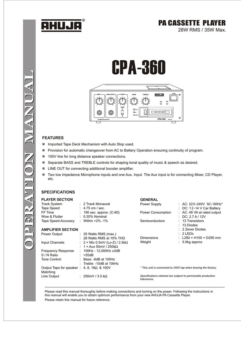
Sharp RT-31 User manual

SHARP
SERVICE
MANUAL
$1
OUTSTANDING RECEPTION THE WORLD
OVER
ATM581
067DCK
Photograph of RT-31
H
Notice: You can make use of the item “DISASSEMBLY”,
regardless of the difference in appearance of the set,
whose photographs are all those of Model
RT-31H
(not RT-31 for SEC.)
SPECIFICATIONS
Power source:
Power consumption:
Semi-conductors:
Dimensions: Width;
Height;
Depth;
Weight:
Tape:
Tape speed
:
Wow
&
flutter:
Frequency response:
Normal tape;
(RT-31
H/HB)
Normal tape;
(RT-31)
AC 11 OV/22OV/24OV,
50160
Hz
(RT-31
H/HB)
AC
12OV,
50/60 Hz (RT-31)
12 wattes (RT-31
H/HB)
10
wattes (RT-31)
7
ICs
(Integrated Circuits)
12 Transistors
9 Diodes
6
LEDs
(Light Emitting Diodes)
430 mm (16-15116”)
1 15.5 mm
(4-9/l
6”)
237 mm
(9-5/l
6”)
3.9 kg (8.6
Ibs)
(RT-31 H/HB)
3.7 kg (8.2
Ibs)
(RT-31)
Philips standard compact cassette
tape
4.8 cm/set.
(
l-7/8
ips.)
0.19% (DIN 45 500)
0.06%
(W.R.M.S.)
(RT-31
H/HB)
0.065% (W.R.M.S.)
(RT-31)
40
-
12,500 Hz (DIN 45 500)
40-ll,OOOHz~3dB
30
-
14,000 Hz
40-12,000Hz+3dB
00
DOLBY
SYSTEM
@
Noise reduction system manufactured under license
from Dolby Laboratories Licensing Corporation.
“Dolby” and the double-D symbol are trademarks of
Dolby Laboratories Licensing Corporation.
RT-31
For
SEC)
RT-31
H
(For
SEEG,
SUK,
SCA
and
General)
RT-31
HB
For
SEW
In the interests of user-safety the set should be
restored to its original condition and only parts
identical to those specified by used.
MAXELL
UDXLII
tape;
(RT-31
H/HB)
40-14,000Hz(DIN45500)
40
-
13,000 Hz
2
3
dB
MAXELL
UDXLII
tape;
(RT-31)
30
-
15,000 Hz
40
-
13,009 Hz
f
3
dB
TDK Metal tape; 40
-
16,000 Hz (DIN 45 500)
(RT-31 H/HB)
40
-
14,000 Hz
f
3
dB
SONY
Fe-Cr
tape; 40
-
14,000 Hz (DIN 45 500)
(RT-31
H/HB) 40
-
13,000 Hz
+
3
dB
S/N ratio (MAXELL
UDXLII
tape):
Dolby
NR
off; 56
dB
Dolby
NR
on; 66
dB
(at over 5
kHz)
Input sensitivity and input impedance:
Microphones;
0.2
mV
(6.8K ohms)
Line in; 50
mV
(50K ohms)
DIN input; 0.2
mV
(6.8K
ohms) (RT-31 H/HB)
Output level and loaded impedance:
Headphones;
46
mV
(“0”
dB)
, 8 ohms
Line out; 550
mV
(“0”
dB), 50K ohms
DIN output; 550 mV
(“0”
dB), 50K ohms
(RT-31 H/HB)
Specifications are subject to change without prior notice.
SHARP
CORPORATION
SHARP
ELECTRONICS
CORPORATION

DISASSEMBLY
(Photographs of RT-31H)
Prior to the disassembly, be sure to remove the AC supply
cord from a wall outlet and the input/output plugs from the
rear of the set. Take out a cassette tape, if loaded in the
cassette compartment,
=
REMOVAL OF CABINET
(See Figures
2-1
and
Z-2)
From the cabinet, remove four screws two each at its
right and left sides, and one screw at its rear surface.
Then take the cabinet off.
Figure 2-l
n
REMOVAL OF BOTTOM PLATE
(See Figure 2-3)
Turn the set upside down, remove two screws from the
bottom plate, and take the bottom plate off by shifting
it in the arrow direction.
n
REMOVAL OF FRONT PANEL
(See Figures 2-4 and 2-5)
1
8
Remove four screws from the front panel.
2 Push down three stoppers at the upper surface of the
front panel, See that the front panel is now free from
the stoppers.
@
Pull the front panel frontwards.
Figure 2-4
n
REMOVAL OF MECHANISM BLOCK
(See Figures 2-6 and
3-l)
Note:
Be sure to open the cassette compartment lid before
disassembling the mechanism block,
1
8
Remove two screws from the bottom of the set.
2 Remove two screws from the rear of the mechanism
block.
@
Detach the tape counter belt from the tape counter.
4 Remove the record/playback selector switch rod.
8
5 Remove four sockets from the mechanism block P.W.
board. Then separate the mechanism block from the set.
Figure 2-2
Figure 2-3
Figure
2-5
Figure
2-6
-2-

Figure 3-l Figure 3-2
’
REMOVAL OF FRONT PANEL CHASSIS
(See Figures 3-2 and 3-3)
Pull out two record level control knobs
Remove one nut from the record level control,
Remove two screws.
Remove eight screws.
Remove one screw. Then the front panel chassis can be
separated from the set.
n
REMOVAL OF METER P.W. BOARD
(See Figure 3-3)
@
Push outward six tabs on the meter
P.W.
board holder,
and remove the meter P.W. board.
Figure 3-3
VOLTAGE
SELECTION
(Use of RT-31H/HB)
The unit is designed to operate from
IIOV,
22OV,
or
24OV,
AC mains.
Check the voltage selector setting on the rear panel before
connecting with the AC supply cord.
Adjust the voltage selector to match your local AC power
supply.
The voltage selector is located on the rear panel of the unit.
If adjustment is necessary, use a screwdriver in order to turn
the selector in either direction until the correct voltage in the
window next to the adjusting screw.
Figure 3-4
CAUTION
(RT-31
H/HB)
If any one of the nylon bands shown in the Figure 3-5 is
once removed for some reason, be sure to reprise it to the
original place in the same appearance as before.
Figure 3-5
-3-

MECHANICAL
ADJUSTMENT
Pinch Roller Spring
Figure 4-l
n
PINCH ROLLER PRESSURE ADJUSTMENT
(See Figure 4-l and 4-2)
1.
Place the unit in play mode,
2. Use a tension gauge (0
-
500
gr.)
to push it to a part
@
of the pinch roller until the pinch roller comes away
the capstan. Next gradually weaken the force in the
reverse direction until the pinch roller hits the capstan
(that is, it begins rotating), then see that tension gauge
is reading 295 to 365 grams.
3. Make sure there are clearances
6
0
,
@and
@
between
the pinch roller lever and sub. chassis.
4. If the above value is not satisfied, adjust the pinch roller
pressure spring by bending it, or replace.
n
TORQUE CHECK AT PLAY, FAST FORWARD AND
REWIND MODES
1. Put a torque measuring cassette into the set.
2. The torque values, in each mode must be as tabulated
below.
n
TAPE SPEED ADJUSTMENT
1. Using a test tape (TEAC, MTT-113C, 8
kHz
record-
ed), play it back at the midpoint but not at the running
start or end point.
2. Connect a frequency counter to the line output socket.
rlgure
4-z
3. Use a bladed screwdriver to adjust, through the adjusting
hole at the bottom of motor, the semivariable resistor
so that the frequency counter reads 2975 to 2995 Hz.
TEST
TAPE
MTT-1
PLAYBACK Mode
Frequency Counter
IIIIlll
13c
000
RECORD/
J
PLAYBACK
\
HEAD Line output socket (SO3 or S04)
Figure 4-3
-
-4-

ELECTRICAL
ADJUSTMENT
=
BIAS CURRENT AND BIAS OSCILLATION FREQUEN-
CY ADJUSTMENT OF RECORD AMPLIFIER
(See Figure 5-l)
*
SW7 is not used for model
RT-31.
I.
Connect VTVM between the test point
TPIOI
(or
TP201)
and ground.
2. Connect the vertical input terminal of oscilloscope to
the VTVM and its horizontal input terminal to CR
oscillator.
3. Apply the signal
105
kHz
from the CR oscillator to the
unit, and push the tape selector switch SW4.
4. Place the unit in record mode and adjust bias oscillation
coil
L303
so that the bias oscillation frequency is
105
kHz,
while watching Lissajous’ figure on the oscillo-
scope.
5. Push tape selector switch
SW6.
6. Adjust semi-variable resistor VR301 (ro VR302) so that
VTVM indicates 70 mV.
7. Make sure the indicated value of VTVM varies according
to each position of tape selector switch as tabulated
below.
n
ERASE VOLTAGE CHECK
(See Figure 5-2)
I.
Connect VTVM between test point
TP301
and
ground.
2. Connect oscilloscope to the output terminal of VTVM,
3. Push the tape selector switch SW6.
4. Place the unit in record mode, then see that VTVM is
value 210
mV.
n
RECORD/PLAYBACK HEAD AZIMUTH ADJUSTMENT
(See Figure 5-3)
1.
Connect VTVM between the test point TP103 (or
TP203) and ground.
2. Push the tape selector switch SW4 and set the Dolby
NR
switch SW3 at off position.
3. Put a test tape (TEAC, MTT-114,
IO
kHz, 250
pWb/mm,
-10
dB
recorded) into the unit and play it.
4. Adjust the head azimuth adjusting screw so that the
indicated value of VTVM reaches the maximum and a
difference in phase becomes as small as possible.
g
PLAYBACK FREQUENCY CHARACTERISTIC CHECK
(See Figure 5-4)
1. Connect VTVM to the line output socket.
2. Push the tape selector switch SW4 and set the Dolby
NR
switch SW3 at off position.
3. Put a test tape (TEAC,
MTT-217G,
12.5
kHz/l
kHz/
40 Hz, 250
pWb/mm,
-10
dB
recorded) into the unit
and play it.
4. See that VTVM is showing the deviation of two different
input signals (40
kHz
and 12.5
kHz)
against the 1
kHz
input, as tabulated below.
Posit ion
Switch Indicated value
I
normal
Push SW4
37
mV
Fe
-
Cr
CrOs Push SW7
Push SW5
41
mV
52
mV
Figure
5-I
Figure 5-2
Figure 5-3
Test Tape
With 40 Hz input
Deviation against 1
kHz
input
shown by VTVM
OdBto6dB
I
With 12.5
kHz
input
(
-3
dB
to 4
dB
I
-
Figure 5-4
-5-

=
PLAYBACK SENSITIVITY ADJUSTMENT
(See Figure 6-l
)
1. Connect VTVM between test point
TP103
(or TP203)
and ground.
2. Push the tape selector switch SW4 and set the Dolby
NR
switch SW3 at off position.
3. Put a test tape (TEAC, MTT-150,400 Hz, 200
pWb/mm,
recorded) into the unit and play it.
4. Adjust semi-variable resistor
VRlOl
(or VR201) so that
580 mV will be indicated on VTVM.
n
RECORD/PLAYBACK SENSITIVITY ADJUSTMENT
(See Figure 6-2)
*
SW7 is not used for model RT-31H.
1. Connect VTVM between test point TP103 (or TP203)
and ground.
2. Connect CR oscillator to the line input socket, and
apply the signal of oscillation frequency 400 Hz, output
level -13
dB
(0
dB
=
1
V) to the unit.
3. Push tape selector switch SW4 and set the Dolby
NR
switch SW3 at off position.
4. Put a normal tape (TEAC, MTT-502, blank) into the
unit, and place it in record mode. Adjust the record
level control VRIOZ (or VR202) so that the reading
of VTVM becomes 390 mV.
5. Playback the normal tape which has been recorded
in the step 4, and adjust the semi-variable resistor
VR103 (or VR203) so that the reading of VTVM be-
comes 410 mV. Repeat the steps 4 and 5 until the
VTVM reading stays in the range from 360
mV
to
460
mV.
6. Put a
CrOs
tape (MAXELL, UDXL
II)
into the unit.
7. Push the tape selector switch SW5, and place the unit in
record mode.
8. Playback the
CrOz
tape which has been recorded in the
step 7, and make sure VTVM indicates the reading
within 326 mV to 487 mV.
m
PEAK LEVEL DISPLAY METER SENSITIVITY ADJUST-
MENT
(See Figure 6-3)
1,
Connect VTVM between test point TPI 02 (or
TP202)
and ground.
2. Set the Dolby
NR
switch SW3 at off position and
input selector switch SW2 at “LINE” position.
3. Connect CR oscillator to the line input socket, and
apply the signal of oscillation frequency
1
kHz,
316
mV
(-10
dB)
to the unit, placing it in record mode.
4. Adjust record level control VR102 (or VR202) so that
VTVM will indicate 580 mV (-4.7 dB).
5. Change the output level of CR oscillator from 316
mV
(-10
dB)
to 305 mV (-10.3
dB),
then adjust the
semivariable resistor VR601 (or VR602) so that the
segments
(LEDs)
up to 0
dB
of the peak level display
meter light up.
6. Again change the output level of CR oscillator from
305 mV (-10.3
dB)
to 295 mV (-10.6 dB), then see
that the segments up to -3
dB
remain lit.
n
DOLBY NOISE REDUCTION CIRCUIT CHECK
(See Figure 6-4)
1. Connect VTVM between test point TPI 03 (or
TP203)
and ground.
2. Push the tape selector switch SW4, and set the input
selector switch
SW2
at LINE
posi;tion
and
Dolby
NR
switch SW3 at off position.
3. Connect CR oscillator to the line input socket, and
apply the signal of oscillation frequency
100
Hz, output
level -35
dB
(0
dB
=
1
V),
to the unit.
Figure 6-l
J
9. Put a metal tape (TDK, AC-71
I)
into the unit.
10.
Push the tape selector switch SW6, and place the unit
in record mode.
11. Playback the metal tape which has been recorded in the
step
10,
and make sure VTVM indicates the reading
within 326
mV
to 487 mV.
12. Put a Fe-Cr tape (SONY, CS-30) into the unit.
13. Push the tape selector switch SW7 and place the unit
in record mode.
14. Playback the Fe-Cr tape which has been recorded
in the step
10,
and make sure VTVM indicates the
reading within 326 mV to 487 mV.
Line
l”PYf
sccket
so1
or
so2
Figure 6-2
Figure 6-3
Frequency
1
kHz 10
kHz
12.5
kHz
Indicated
45.7 to 44.5 to 42.6 to
Value 81
mV
70 mV 68.2 mV
A
Table
1
Frequency
1
kHz
10
kHz
12.5
kHz
Indicated
8.2 to 13.7 to 13.5 to
Value 16.4
mV
24.9 mV 23.4 mV
Table 2
Figure 6-4
-6-
4. Put a normal tape into the unit and place it in record
mode. Adjust the record level control
VRI
02 (or 6. Give the set the
signal
of oscillation frequency 100 Hz,
output level -50
dB
(0
dB
=
1 Vi, then adjust the record
VR202) so that VTVM
WIII
indicate 32.6
mV.
5. Give the set
1
kHz
signal,
10
kHz
signal and 12.5
kHz
level control VR102 (or VR202) so that VTVM will
indicate 5.8 mV.
signal one after another, then see that VTVM indicates
the reading listed in Table 1. 7. In the same manner as in the step 5 give the set 1
kHz
signal,
10
kHz
signal and 12.5
kHz.
Consequently, make
sure VTVM indicates the reading listed in Table 2.
ALIGNMENT
POINTS
Figure 7-l
VHILA3160//-1
(ICI)
~-fijTJ
FRONT
VIEW
rlgure
I--L
tuuIvHLtI\I
I
l;iKLuI
I

I
i
i
II
I
f:
Q301,0302
2SCl214C
P70
I
2SA733K
MARKING SIDE
(Specifications or wiring diagrams of this model
L
7
2
I
FILIOI
FI
L20
I
NOTES:
07022SD794P
~1
are subject to change for improvement without prior notice.)
3
I
4
5
I
6
Figure 9 SCHEMATIC
c

7
8910
11
12
2SC945AP
T-
0105,0205
7
2SC945AP
o,.*
,-I-=
A3_= 2SC945AP
C
0
E
F
G
ITES:
Parts marked with
“Q”
(01
are
im-
1. Resistor: 2. Capacitor:
portant
for maintaining the safety of the To differentiate the units of resistors, such To indicate the unit of capacitor, a symbol
P
set. Be sure to replace these parts with symbols as
K
and Mare used; the symbol
K
used; this symbol
P
means
micro-microfar:
specified ones for main taining the means 1000 ohm and the symbol
M
means and the unit of the capacitor without
sur
safety and performance of the set.
lOOOK
ohm and the resistor without anysymbol
is
microfarad. As to
electrolyt
symbol is ohm-type resistor. Besides, the one capacitor, the expression “capacitance/wit
with “Fusible” is a fuse type. stand voltage” is used.
is
id
:h
ic
h-
H
1
I
7
I
8
I
9
I
10
11
12
1
TIC DIAGRAM
(RT31H/HB)
-lO-
.--____
~..
_^
.-
.__-_
__--.--
-..._,..
x
__-__
-
..-.-.
-.-
--.-...-.-._.
_--____
I-
-__.-l”__--

1
23
I
4
56
r
E
F
G
H
~
-
rLiNE
1
--_-
r-------
-
1
2
34
I
5
-6
I’
Figure 11 WIRING SIDE OF PRINT
-ll-

7
8910
11
12
4
A
AV
II
II
/I
II
II
f&h
B
3
C
D
I
I
--_
----------------
____
~
A-----
------
------~
1
E
F
G
:
H
!’
7
I
8
I
9
10
I
11
I
12
IF
PRINTED WIRING BOARD
(RT91H/HB)
-12-
--.--.---------
..-.
---.---
______-_
----_--
-
.__-
-_---

1
234
5
6
Q102,9202
2SC945AP
~1
A
B
C
0
E
F
G
:
H
a70
I
2SA733K MARKING SIDE
~301,0302
2SCl214C
0702
2507940
FILIOI
FIL201
NOTES:
Pa
PC
se
%LoM
SP
sa
(Specifications or wiring diagrams of this model are subject to change for improvement without prior notice.)
1
I
2
I
3
I
4
I
5
I
6
Figure 13 SCHEMATIC
DIL
-13-

I
0103,0203
2SC945AP 0104,0204
2SC945AP Q105,0205
2SC945AP
r
-+-
C
l
I
W-J
D
,
,
,----
-
------
--
I
,’
//
I
_-
E
l-
.’
I I
t
!=
-I
1
I’p,““’
I
I
‘ES: Parts marked with
“A”
(0)
are
im-
1. Resistor: 2. Capacitor:
portant
for maintaining the safety of the To differentiate the units of resistors, such To indicate the unit of capacitor, a symbol
P
i:
set. Be sure to replace these parts with symbols as
K
and Mare used; the symbol
K
used; this symbol
P
means micro-microfarao
specified ones for main
taming
themeans 1000 ohm and the symbol Mmeans and the unit of the capacitor without suer
safety and performance of the set.
IOOOK
ohm and the resistor without anysymbol
is
microfarad. As to electrolytic
svmbol
is ohm-Woe resistor. Besides. the one capacitor, the expression “capacitance/with
-,
with “Fusible” is a fuse type. stand voltage” is used.
I
j
7
810
I
11
12
IC
DIAGRAM
(FIT-31)
-14-

.
*
-.-
-
-
-swI(A
r------- ---------
~aaomomoc3a~~o8
L-N---M_--C--X--J--i--~---~---~--~--~---~--~--~-i
:,
CT-1-t
--=zf
-A---x-
-=
+,G+-
,
cm*
,?,+
1
2 3
I
45
/
6
I
Figure 15 WIRING SIDE OF
PRI
-15-

7
8910
11
12
i
I
___---L---_---__--
---,
--_------__--------
I/
11
SW!
I
SWIZ
PIPS
~’
-
SWlTCH
BIAS
SWlTCH
1
I
II
’
I
‘1
I
LEFT
.
MIC
I
I
_1_
I.
7
I
8
I
9
I
10
I
11
I
12
llTED
WIRING BOARD (RT-31)
-16-

I
TOP
G)
n
m
0
0
m
D
1
BOTTOM
Figure 17 MECHANISM EXPLODED VIEW
ll
In
00
m
D

1
23
456
-
I1
$
‘\I
Y
,
0
L
,”
t,A
,’
,’
,’
2
,*’
J/
-3s
-c
p
ii
E
F
01-504
3
1
A
B
C
D
E
F
G
!
H
I
2
3 4 5
6
*
Figure 18 CABINET EXPLODED VIEW (Use of
RTSlH/HB)
-18-

REPLACEMENT PARTS LIST
REF. NO. PART NO. DESCRIPTION CODE
INTEGRATED CIRCUITS
ICI
ICZ, 3
IC4
IC5.6
IC7
VHI
LA3160//-1
Pre-amplifier (Record/ AG
playback)
(LA3160)
VHINE646B//lF
Dolby B-type Noise Reduc- AM
tion Circuit
(NE64651
VHIIR3108//-1
APSS Circuit
(IR3108)
AK
VHIIR2E02//-1
Peak Level Display Meter AL
Driver (I
R2E02)
VHIHA178M15-1
Hall Element
(HA178M15)
AK
TRANsisToRs
(RT~IH/HB)
0102,202
VS2SC945AP/-I
0103,203
VS2SC945AP/-1
0104,204
VS2SC945AP/-1
0105.205
VS2SC945AP/-I
0301,302
vs2sc1214-c-i
0701
VS2SA733-K/-l
0702
VS2SD794-Q/-l
Switching, Dolby
AB
(2SC945AP)
Record Equalization
AB
Amplifier
(2SC945AP)
Muting
(2SC945AP)
A6
Audio Amplifier (Head-
AB
phones)
(2SC945AP)
Bias Oscillation
(2SCl214C)
AC
APSS Circuit
(2SA733K)
AC
APSS Solenoid Driver AE
(2SD794Q)
0102,202
0103.203
0104,204
0105,205
TRANSISTORS (RT-31)
2SC945AP
Switching, Dolby AB
(VS2SC945AP/-1)
2SC945AP
Record Equalization
Ampli-
AB
fier
(VS2SC945AP/-1)
2SC945AP
Muting
(VS2SC945AP/-1)
AB
2SC945AP
Audio Amplifier (Head-
AB
phones)
(VS2SC945AP/-I)
Q301,302
Q701
a
Q702
2sc1214c
2SA733K
2SD794Q
Bias Oscillation
(VS2SC1214-C-1)
APSS Circuit
(VS2SA733-K/-l)
APSS Solenoid Driver
(VSZSD794-Q/-l)
AC
AC
AE
ZENER DIODE
(RT31H/HB)
DIODES AND LEDS (RT-31H/HB)
Dl
01,201
D301
D401
0504,505,
D506,507
D601,602,
D603
V
HDl
S2076//-1
Muting
(1
S2076)
RH-PX1029AFZZ
LED, Record Indicator
(G
L-9PR25)
RH-DX1006AFZZ
Surge Absorver
(1
OE
1)
i
VHDlOEl////-1
Power Rectifier
(10El)
AB
AC
AB
AC
I
RH-PX1027AFZZ
LED, Peak Level Indicator
1
LT.3006P)
AK
“HOW TO ORDER REPLACEMENT PARTS”
To have your order filled promptly and correctly, please furnish the following information.
1. MODEL NUMBER
2.
REF. NO.
3. PART NO. 4. DESCRIPTION
As to Transistors, Diodes, Zener Diode and LED described in this parts list, they are different according to the Model RT-
31
H/HE
or RT-31, A distinction is drawn between the
abovedescribed
items by description of the used units parenthesized.
NOTES: Parts marked with
“Q”
(I)
are important for maintaining the safety of the set. Be sure to replace these parts with
specified ones for maintaining the safety and performance of the set.
I
I
/I
REF. NO. PART NO. DESCRIPTION CODE
D502,604,
D605,606,
D607
D608,609,
D610
D501,611,
D612.613,
D614
D701
RH-PX1026AFZZ
LED, Peak Level Indicator
(LT.3001
N2)
AG
RH-PXl027AFZZ
LED, Peak Level indicator
1
LT-3006P)
AK
RHPX1026AFZZ
LED, Peak Level indicator
1
LT-3001
N2)
AG
3702
D703
VHDlS2076//-I
Reverse Current Prevention
AB
(I
S2076)
RH-PX1028AFZZ
LED, APSS Indicator AC
(G
L-9NG35)
VHDI
S2076//-1
Reverse Current Prevention
AB
(152076)
DIODES AND
LEDS
(RT-31)
D101.201
D301
3401
1
S2076
G
L8PR25
lOE1
Muting
(VHDlS2076//-1
)
AB
LED, Record Indicator AC
(RH-PX1029AFZZ)
Surge Absorver AB
(RH-D~i006~Fzz)
D504,505,
D506,507
3601,602,
3603
lOE1
LT.3006P
Power Rectifier
(VHDlOEl////-1)
AC
LED, Peak Level Indicator
(RH-PX1027AFZZ)
AK
II
I
I
I
I
I
I
I
I
I
D502.604,
3605,606,
2607
D608.609
D610
1501,611,
3612,613,
II614
3701
LT-3001
N2
LT-3006P
LED, Peak Level Indicator
(RH-PXl026AFZZ)
AG
LT-3001
N2
LED, Peak Level Indicator
(RH-PX1027AFZZ)
AK
LED, Peak Level Indicator
(RH-PX1026AFZZ)
AG
3702
3703
1
S2076
G
L-9NG35
1
S2076
Reverse Current Prevention
(VHDlS2076//-I
)
LED, APSS Indicator
(RH-PXl028AFZZ)
Reverse Current Prevention
(vHDI
S2076//-1)
AB
AC
AB
CD101
VHERD4R7JB2-1
Reverse Current Prevention
IRD4.7JB2)
AB
ZENER DIODE (RT-31)
ZDIOI
RD4.7JB2
Reverse Current Prevention
(VHERD4R7JB2-I)
AB
COILS
LlOl,
201 RCI
LZ0086AFZZ
Record Equalizer
(6.8mH)
AC
L301,302
RCI
LB0499AFZZ
Bias Step-up AD
L303
RCI
LB0555AFZZ
Bias Oscillation
AE
L401
RCILZ0062AFZZ
Noise Killer (100,~H) AC
-21-

+
For VHI LA3160//-1 (ICI
),
see Figure 7-2
on
Page
7.
VHINE646B//l
F
(IC2,
IC3)
I
DOLBY B-TYPE
’
‘OWE
R
CIRCUIT
TOP VIEW
=
N/C
-i OUTPUT
01
OUTPUT
uINPUT
*
REFERENCE
”
OUTPUT
N
IN PUT
-
INPUT
Figure
20-I
BLOCK DIAGRAM
VHIIR3108//-1
(IC4)
FRONT VIEW
Figure
20-2
BLOCK DIAGRAM
TOP VIEW
Figure
20-3
BLOCK DIAGRAM
VHIHA178M15-1 (IC7)
FRONT VIEW
Figure
20-4
EQUIVALENT CIRCUIT

1
2
I
3 4 5 6
&
_,’
-:
b
;!
,’
,_‘.
.,
-2
i
F
G
H
1
I
2
3 4 5 6
Figure 19 CABINET EXPLODED VIEW (Use of
RT-31)
-19-
A
B
C
D
E
This manual suits for next models
2
Table of contents
Other Sharp Cassette Player manuals

Sharp
Sharp Searcher GF-6060H User manual

Sharp
Sharp RT-350H User manual

Sharp
Sharp WQ-T360H User manual

Sharp
Sharp GF-8H User manual

Sharp
Sharp SC-700H User manual

Sharp
Sharp GF-9696H User manual

Sharp
Sharp The Searcher GF-9797H User manual

Sharp
Sharp WQ-CD54H User manual

Sharp
Sharp QT-90W User manual

Sharp
Sharp QT-CD44H User manual

Sharp
Sharp GF-9292X User manual

Sharp
Sharp WQ-700H User manual

Sharp
Sharp WQ-290H User manual

Sharp
Sharp RT-9100H User manual

Sharp
Sharp VZ-2000 User manual

Sharp
Sharp QT-222WS User manual

Sharp
Sharp QT-30GD User manual

Sharp
Sharp JC-S58H User manual

Sharp
Sharp QT-80W User manual

Sharp
Sharp WF-1100W User manual