Sharp LC-24LE170I User manual

SERVICE MANUAL
Parts marked with " " are important for maintaining the safety of the set. Be sure to replace these parts with specified ones for maintaining the
safety and performance of the set.
This document has been published to be used for
after sales service only.
The contents are subject to change without notice.
SAFETY PRECAUTION
IMPORTANT SERVICE SAFETY PRE-
CAUTION ............................................................i
PRECAUTIONS FOR USING LEAD-FREE
SOLDER ............................................................ii
CHAPTER 1. OUTLINE
[1] OUTLINE ...................................................... 1-1
........ 7-1
........ 8-1
........ 9-1
........ 9-5
........ 9-7
CHAPTER 2. SPECIFICATIONS
[1] SPECIFICATION .......................................... 2-1
CHAPTER 3. OPERATION MANUAL
[1] OPERATION MANUAL ................................ 3-1
CHAPTER 4. DIMENSIONS
[1] DIMENSIONS .............................................. 4-1
CHAPTER 5. REMOVING MAJOR PARTS
[1] REMOVING OF MAJOR PARTS ........................ 5-1
CHAPTER 6. ADJUSTMENT
[1] ADJUSTMENT ............................................. 6-1
CHAPTER 7. TROUBLE SHOOTING TABLE
[1] TROUBLE SHOOTING TABLE.............
CHAPTER 8. OVERALL WIRING/SYSTEM BLOCK
DIAGRAM
[1] SYSTEM BLOCK DIAGRAM................
CHAPTER 9. PRINTED WIRING BOARD
ASSEMBLIES
[1] MAIN UNIT............................................
[2] LED RC UNIT.......................................
[3] POWER UNIT.......................................
..... 10-1
..... 10-4
...... 10-2
...... 10-6
CHAPTER 10. SCHEMATIC DIAGRAM
[1] DESCRIPTION OF SCHEMATIC
DIAGRAM..............................................
[2] MAIN UNIT ...........................................
[3] LED RC UNIT .......................................
[4] POWER UNIT ......................................
Parts Guide
TopPage
LC-24LE170I
CONTENTS
LED BACKLIGHT TV
LC-24LE170I
MODEL
In the interests of user-safety (Required by safety regulations in some countries) the set should be restored to its orig-
inal condition and only parts identical to those specified should be used.

LC-24LE170I
i
LC-90LE740X Service Manual
SAFETY PRECAUTION
IMPORTANT SERVICE SAFETY PRECAUTION
WARNING
1. For continued safety, no modification of any circuit should be
attempted.
2. Disconnect AC power before servicing.
BEFORE RETURNING THE RECEIVER (Fire &
Shock Hazard)
Before returning the receiver to the user, perform the following
safety checks:
3. Inspect all lead dress to make certain that leads are not pinched,
and check that hardware is not lodged between the chassis and
other metal parts in the receiver.
4. Inspect all protective devices such as non-metallic control knobs,
insulation materials, cabinet backs, adjustment and compartment
covers or shields, isolation resistor-capacitor networks, mechanical
insulators, etc.
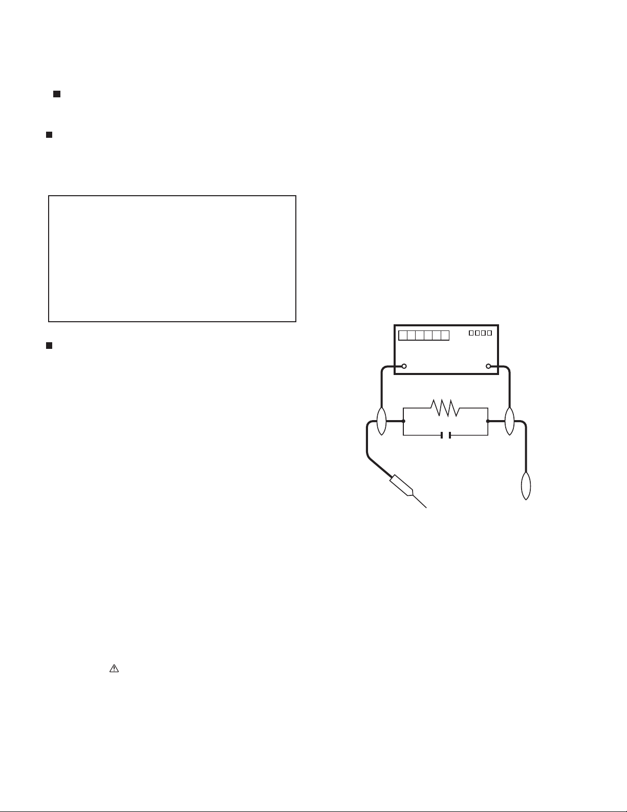
5. To be sure that no shock hazard exists, check for leakage current
in the following manner.
•Plug the AC cord directly into a 110-240 volt AC outlet.
•Using two clip leads, connect a 1.5k ohm, 10 watt resistor paral-
leled by a 0.15µF capacitor in series with all exposed metal cabinet
parts and a known earth ground, such as electrical conduit or elec-
trical ground connected to an earth ground.
•Use an AC voltmeter having with 5000 ohm per volt, or higher, sen-
sitivity or measure the AC voltage drop across the resistor.
•Connect the resistor connection to all exposed metal parts having a
return to the chassis (antenna, metal cabinet, screw heads, knobs
and control shafts, escutcheon, etc.) and measure the AC voltage
drop across the resistor.
All checks must be repeated with the AC cord plug connection
reversed. (If necessary, a nonpolarized adaptor plug must be used
only for the purpose of completing these checks.)
Any reading of 0.75 Vrms (this corresponds to 0.5 mA rms AC.) or
more is excessive and indicates a potential shock hazard which
must be corrected before returning the monitor to the owner.
///////////////////////////////////////////////////////////////////////////////////////////////////////////////////////////////////////////////////////////////////////////////////////////////////////////////////////////////////////////
SAFETY NOTICE
Many electrical and mechanical parts in LCD color television have
special safety-related characteristics.
These characteristics are often not evident from visual inspection, nor
can protection afforded by them be necessarily increased by using
replacement components rated for higher voltage, wattage, etc.
Replacement parts which have these special safety characteristics are
identified in this manual; electrical components having such features
are identified by " " and shaded areas in the Replacement Parts List
and Schematic Diagrams.
For continued protection, replacement parts must be identical to those
used in the original circuit.
The use of a substitute replacement parts which do not have the same
safety characteristics as the factory recommended replacement parts
shown in this service manual, may create shock, fire or other hazards.
///////////////////////////////////////////////////////////////////////////////////////////////////////////////////////////////////////////////////////////////////////////////////////////////////////////////////////////////////////////
Service work should be performed only by qualified service technicians who are thoroughly familiar with all safety checks and the
servicing guidelines which follow:
CAUTION:FOR CONTINUED PROTECTION
AGAINST A RISK OF FIREREPLACEONLYWITH
SAME TYPE FUSE.
F7001 (250V6.3A)
DVM
AC SCALE
1.5k ohm
10W
TO EXPOSED
METAL PARTS
CONNECT TO
KNOWN EARTH
GROUND
0.15
µ
F
TEST PROBE

LC-24LE170I
ii
PRECAUTIONS FOR USING LEAD-FREE SOLDER
Employing lead-free solder
•“PWBs” of this model employs lead-free solder. The LF symbol indicates lead-free solder, and is attached on the PWBs and service manuals. The
alphabetical character following LF shows the type of lead-free solder.
Example:
Using lead-free wire solder
•When fixing the PWB soldered with the lead-free solder, apply lead-free wire solder. Repairing with conventional lead wire solder may cause dam-
age or accident due to cracks.
As the melting point of lead-free solder (Sn-Ag-Cu) is higher than the lead wire solder by 40 °C, we recommend you to use a dedicated soldering
bit, if you are not familiar with how to obtain lead-free wire solder or soldering bit, contact our service station or service branch in your area.
Soldering
•As the melting point of lead-free solder (Sn-Ag-Cu) is about 220 °C which is higher than the conventional lead solder by 40 °C, and as it has poor
solder wettability, you may be apt to keep the soldering bit in contact with the PWB for extended period of time. However, Since the land may be
peeled off or the maximum heat-resistance temperature of parts may be exceeded, remove the bit from the PWB as soon as you confirm the
steady soldering condition.
Lead-free solder contains more tin, and the end of the soldering bit may be easily corroded. Make sure to turn on and off the power of the bit as
required.
If a different type of solder stays on the tip of the soldering bit, it is alloyed with lead-free solder. Clean the bit after every use of it.
When the tip of the soldering bit is blackened during use, file it with steel wool or fine sandpaper.
•Be careful when replacing parts with polarity indication on the PWB silk.
Lead-free wire solder for servicing
Indicates lead-free solder of tin, silver and copper. Indicates lead-free solder of tin, silver and copper.
PARTS CODE PRICE
RANK
PART
DELIVERY DESCRIPTION
ZHNDAi123250E BL J φ0.3mm 250g (1roll)
ZHNDAi126500E BK J φ0.6mm 500g (1roll)
ZHNDAi12801KE BM J φ1.0mm 1kg (1roll)

LC-24LE170I
1 – 1
LC-90LE740X Service Manual
CHAPTER 1. OUTLINE
[1] OUTLINE
MAJOR SERVICE PARTS
PWB Unit
OTHER Unit
No. PARTS CODE DESCRIPTION
N B3KUE170I MAIN / POWER UNIT
N B3KUE175I2 LED / IR UNIT
No. PARTS CODE DESCRIPTION
N RLCDTA345WJQZ PANEL HIRAKI
N RUNTKB356WJZZ LED BAR (A)
N RUNTKB357WJZZ LED BAR (B)
N CLCDTA381WE07 PANEL ASSEMBLY

LC-24LE170I
2 – 1
LC-90LE740X Service Manual
CHAPTER 2. SPECIFICATIONS
[1] SPECIFICATIONS
Specifications
Item Model LC-24LE170I
LCD Panel 23.5” (598 mm) TFT LCD
Resolution 1.049.088 pixels (1366 ×768)
Video Colour System PAL/SECAM/NTSC 3.58/NTSC 4.43
TV
Function
TV-Standard PAL: B/G, D/K, I SECAM: B/G, D/K, K/K
1
NTSC: M
Receiving
Channel
VHF/UHF 43,25—863,25 MHz
CATV
S1—S41ch (including Hyperband)
TV-Tuning System Auto Preset 99 ch
STEREO/BILINGUAL NICAM: B/G, I, D/K A2 stereo: B/G
º671:Vº671:HViewing angles
Audio amplifier/Speakers 3 W × 2 / 3 × 5 cm 2 pcs
Terminal Antena input UHF/VHF 75
ΩDIN type
INPUT 1 HDMI (HDMI input), PC input
INPUT 2 VIDEO in, AUDIO in, COMPONENT in
OUTPUT AUDIO out, Headphone ( 3,5 mm stereo)
English/S implified Chinese/Arabic/French/Portuguese/Russian/Persian/Thai/OSD language
Vietnamese/Indonesian
zH06/05,V042—011CAPower Requirement
)agaiSW0,5(W29Power Consumption
Dimensions without stand 549 (W) × 326,3 (H) × 83,4 (D) mm
549 (W) × 346,3 (H) × 149,2 (D) mm
with stand
2,7 kg (without stand) / 2,9 kg (with stand)Weight
Operating Temperature 0°C — 40°C

LC-24LE170I
3 – 1
LC-90LE740X Service Manual
CHAPTER 3. OPERATION MANUAL
[1] OPERATION MANUAL
Remote control sensor
Part names
TV (Front)
POWER indicator
Light off Power off.
Lighted (Red) The TV is in standby mode.
Lighted (Green) The TV is on.
TV (Rear)
* Usually do not connect anything to this terminal as it reserved only for service personnel.
•
The illustrations in this operation manual are for explanation purposes and may vary slightly from the actual operations.
SERVICE
ONLY AUDIO (L/R)
POWER
3
7
8
4
5
6
JOG-KEY BASIC
FUNCTION
FUNCTION
DURING MENU
CH UP *
CH DOWN *
+VOL UP +*
–VOL DOWN –*
(BELOW 1 SEC) INPUT SELECT/
ENTER
(1 SEC AND
OVER) MENU RETURN/
MENU EXIT
* Tombol ulangi
1SERVICE ONLY terminal *
2 INPUT 2 terminal
(COMPONENT/AV INPUT)
3 INPUT 1 (HDMI) terminal
4 Antenna input terminal
5 SERVICE ONLY terminal *
6AUDIO output (R/L) terminal
7 POWER (on/off) button
8 Keypad control
1
2
PR(CR) PR(CB) VIDEO/ Y
SERVICE
ONLY
L AUDIO R

3 – 2
Remote control unit
7
Set the volume.
( ) Increase the volume.
( ) Decrease the volume.
8 (Mute)
Press Mutes sound.
Press again Restores sound.
Mute will be cancelled after 30 minutes. However, the TV
will not suddenly output loud sound as the volume level will be
set to 0 automatically. Increase the volume level by pressing
.
9 ///(Cursor)
Select a desired item on the setting screen
ENTER
Execute a command.
10 WIDE
Change the wide image mode.
11 ECO
Reduce overall power consumption based on user
preferences.
12 TIMER
Set the Sleep timer and Reminder.
13 INPUT (INPUT SOURCE)
Select an input source.
14 CH /CH
TV input mode: Select the channel.
(CH ) Increase the channel number.
(CH ) Decrease the channel number.
15 MPX
Select the sound multiplex mode.
16 MENU
Display the menu screen.
17 RETURN
MENU mode: Return to the previous menu screen.
1 POWER (STANDBY/ON)
To switch the power on and off
2 DISPLAY
Display the channel or input information.
3 SURROUND
Select surround setting.
4 0 – 9
Set the channel.
5 (Flashback)
Press to return to the previous selected channel
or external input mode.
6 AV MODE
Select an audio and video setting.
VOL + /VOL –
VOL +
VOL +
VOL –
SURROUND TIMER
WIDE
LCDTV
GB176WJSA
1
2
5
7
8
9
10
6
3
4
11
12
13
14
16
15
17
LC-24LE170I

3 – 3
Attaching the stand
•Before attaching (or detaching) the stand, unplug the AC cord from the AC outlet.
•Before performing work spread cushioning over the base area to lay the TV on. This will prevent it from
being damaged.
1Confirm the screws supplied with the TV.
Screws ( ×4)
(used in step 2)
2Insert the stand base to the right and the left
of the bottom of the TV. ( )
3Insert and tighten the 4 screws into the holes
on the bottom of the stand base. ( )
NOTE
•To detach the stand, perform the steps in reverse order.
•Do not attach or detach the stand without holding it. Doing
so can cause the stand to fall, resulting in serious personal
injuries as well as damage to the stand.
1
2
Obeng
Sekrup
Kain lembut
Dudukan
LC-24LE170I

4 – 1
CHAPTER 4. DIMENSIONS
[1] DIMENSIONS
LC-24LE170I

5 – 1
Service Manual
CHAPTER 5. REMOVING OF MAJOR PARTS
[1] REMOVING OF MAJOR PARTS
.
3 3
1. Removing of Stand Unit and Rear Cabinet Ass’y.
1. Remove the 4 lock screws (1), detach the Stand Unit R (2) and Stand Unit L (2).
2. Remove the 2 screws (3), 1 screw (4), and detach AC Cord Cover (5)
3. Remove the 2 screws (6), 10 screws (7), and detach Rear Cabinet Ass’y
5
5
1
5
7777
7
7
22
7
6
7
1
4
6
LC-24LE170I

5 – 2
Service Manual
4
31
1 2
5
5
5
1
1. Removing Speaker L/R and PWB Chassis.
1. Disconnect SP Wire and remove speaker (1).
2. Disconnect BL/IR Wire (2).
3. Disconnect AC Cord (3).
4. Disconnect LVDS FFC Wire (4), remove 3 screws (5), and remove PWB Chassis.
LC-24LE170I

LC-24LE170I
5 – 3
Service Manual
1 1 1 1 1
1
1
1
1
1
1
1
1
1 1 1 1 1 1
1. Removing of the LCD Panel Module
1. Remove Cab A by release 19 hook (1).

LC-24LE170I
6 – 1
CHAPTER 6. ADJUSTMENT
[1] ADJUSTMENT
3.
Software
upgradin
g.
1) Plug o the LCD
TV.
2) Insert the USB device to the USB terminal at the LCD
TV.
(Make sure that the latest software is installed in the USB
device).
3) Hold the LCD TV power key and plug on the LCD
TV.
4) LCD TV is on and detecting the USB
device.
5) A few seconds later, L ED lig h t ( o r a n g e ) w i l l b l i n k i n d i c at i n g the software
upgrading.
7) TV will automatically restart when software is successfully installed
8) LCD TV is running with the latest software.
[1]
ADJUSTMENT PROCEDURE
1.
Entering
and cancel
the adjustment process mode
1) While holding down the POWER and CENTER keys at the same time, plug in the AC CORD to turn the power
Backlight turned ON, screen display show Black pattern and LED blinking GREEN --> RED --> GREEN --> RED.
2)
Enter password “UP (CH UP) --> DOWN (CH DOWN) --> UP (CH UP)”. (After 30 sec password not keyed in or password keyed in wrong, go to previous
Power Status (On, Standby or OFF).
3)
2.
Remote controller
key operation and description
of display in adjustment process mode.
Remote controller key
Main
unit key
F
unc
tion
CH ( /
)
Changing selecting ine (UP/DOWN)
VOL(+ /
–)
Cursor ( /
)
——————
egapagninruT
(PREVIOUS/NEXT)
Cursor ( /
)
Changing
a selected line setting
(+10/-10)
INPUT button on
remote
controller
CENTER elggot(gnihctiwsecruostupnI
switching)
(TV INPUT1 INPUT2
)
RETNE
* Input mode is switched aut omat icall y when relevant adjustment is started so far as the
necessary
input signal is
available.
Backlight turned ON, screen display show Purple test pattern (LED still blinking GREEN --> RED --> GREEN --> RED)
4)
Press the Center Key (The adjustment process mode screen appears).
5)
——————
——————
UP/DOWN
LEFT/RIGHT
Changing selecting line setting (+1/-1)
Enter

LC-24LE170I
6 – 2
1. SIGNAL ADJUSTMENT
A. PICTURE ADJUSTMENT
Confirmation of signal from generator (setting to spec level)
PAL Composite signal :0.7Vp-p ±0.02Vp-p (pedestal to white level)
33K Component signal (60Hz) :Y level :0.7Vp-p ±0.02Vp-p (pedestal to white level)
Pb, Pr level :0.7Vp-p :0.7Vp-p ±0.02Vp-Com
(1) Adjustment Mode
NO.
ITEM
CONDITION
PROCEDURE
i
Adjustment Mode
Press the test key at the test remote control
(2) Component 33K 60Hz Signal Adjustment (COMP-HD)
NO.
ITEM
CONDITION
PROCEDURE
i
Setting
[Signal]
COMP 33K 60Hz
(1080i)
100% Full-field Colour
Bar
[Terminal]
COMPONENT
INPUT 2
・Feed the COMPONENT 33K 60Hz (1080i) 100% Full-field
Colour Bar signal(100% colour saturation) to COMPONENT
INPUT 2
ii
Auto Adjustment
Test Mode page 5
(COMP HD)
At the related page, move cursor to [COMP HD ADJ], press
ENTER.
[OK] appears when finished.
100% White→←Black

LC-24LE170I
6 – 3
B. WHITE BALANCE ADJUSTMENT
a) White Balance Adjustment
NO
.
ITEM
CONDITION
PROCEDURE
i
Setting
Backlight : MAX
AV Mode : DYNAMIC
Active Backlight : OFF
Set the luminance
meter on the centre of
the screen
For the details of white balance adjustment procedure, please refer to white balance
adjustment spec for Kameyama model.
1. Confirm the set condition.
2. Connect the white balance jig.
3. Through RS-232C command, adjustment mode screen is displayed.
ii
Auto
Adjustment
[command]
Adjustment
Mode
KRSW0001
KKT10037
Setting
KYOF0001
OSDS0001
SBSL0016
Multi point
adj. Mode
MSET0000
WBI20255
Point 2
WBI20227
MG2G****
MG2B****
MG2R****
Point 1
WBI10051
MG1G****
MG1B****
MG1R****
Write
MSET0003
Set
Max.Level
MGMG****
MGMR****
MGMB****
Initial setting
Panel Contrast
R/G/B_MAX
R/G/B_HIGH
R/G/B_LOW
Cnt = 3000:1
WBMAX = 4080
WBH= 3664/4080
WBL= 816/4080
(1) Measurement MAX Brightness
(2) Set MIN Brightness
(3) Measurement HIGH Brightness
(4) Measurement LOW Brightness
(5) Calculation H γ
(6) Calculation Lγ
(7) Calculation HIGH luminance (γ=2.2)
(8) Calculation Initial setting of R/G/B_HIGH
(9) Set Initial setting of R/G/B_HIGH
(10) Original WB adjustment is performed (HIGH)
Set the specified gradation for point 2, fix the
most faint colour to get reference value, adjust
others 2 colours to minus adjustment for
reference value of point 2.
(11) Measurement
HIGH Brightness
(Set)
R_HIGH= G_HIGH
G_HIGH= G_HIGH
B_HIGH= G_HIGH
(12) Calculation MAX luminance after WB
ADJ set to γ=2.2 (LXHG)
(13) Set R/G/B_MAX
(14) Calculation LOW luminance (γ=2.2)
(15) Calculation Initial setting of R/G/B_LOW
(16) Set Initial setting of R/G/B_LOW
(17) Original WB adjustment is performed (LOW).
Set the specified gradation for point 1. adjust RB
to the reference value of point 1.
(18) Adjusted value is writing at [command]
MSET0003
(19) Calculate the slope R2slope, G2slope, B2slope
between MAX and Point2.
R2slope = (Rmax
- Rhigh )/(4080-3664)
Lmax=305.7 cd/m²
Lmin= Lmax/Cnt = 0.102
LXH=235.1 cd/m²
LXL=2.06 cd/m²
Hγ=LOG((LXH-Lmin)/(Lmax-Lmin))/LOG(WBH/WBMAX)= 2.44
Lγ=LOG((LXL-Lmin) /(Lmax-Lmin))/LOG(WBL/WBMAX)=2.73
LH22=(Lmax-Lmin) x (WBH/WBMAX)^2.2+Lmin=241.31
WBHX=WBMAX X ((LH22-Lmin)/(Lmax-Lmin))^(1/H γ)=3703
R_HIGH=WBHX’=3703
G_HIGH=WBHX’=3703
B_HIGH=WBHX’=3703
R_HIGH=3702
G_HIGH=3641
B_HIGH=3703
R_HIGH=3641
G_HIGH=3641 LXHG=231.3
B_HIGH=3641
LXMX=LXHG/((WBH/WBMAX)^2.2)=293.04
R_MAX=G_MAX*(R_HIGH/G_HIGH)=4078
G_MAX=WBMAX X ((LXMX-Lmin)/(Lmax-Lmin))^(1/Hγ)=4010
B_MAX=G_MAX*(B_HIGH/G_HIGH)=4078
LXLX=(LXMX-Lmin) x (WBL/WBMAX)^2.2+Lmin=5.08
WBLX=WBMAX X ((LXLX-Lmin)/(Lmax-Lmin))^(1/Lγ)=901
R_LOW=WBXLX=901
G_LOW=WBXLX=901
B_LOW=WBXLX=901
R_LOW= 921
G_LOW=901
B_LOW=971
Example: G6 panel also use for G8/
CSOT, CMI (be careful of INT setting)
RESULT
RESULT

LC-24LE170I
6 – 4
(20) Calculate the correction value
⊿Rhigh, ⊿Ghigh, ⊿Bhigh.
⊿Rhigh = R2slope X (3840-3664)
(21) Set the reference value R,G,B of point 2
(R2’)=R2+⊿Rhigh
(22) Calculate the slope R1slope, G1slope, B1slope
between Point2 and Point1.
R1slope = (Rhigh - Rlow )/(3664-816)
(23) Calculate the correction value ⊿Rlow, ⊿Glow,
⊿Blow.
⊿Rlow = R1slope X (915-816)
(24) Set the reference value R,G,B of point 1
(R1’)=R1+⊿Rlow
(25) Shut down the AC power.
※Initial value at RGB 2 point : 3664
※Initial value at RGB 1 point : 816
[Adjustment value]
☆Teaching set send by engineering dept is set as
reference.
[Reference values for adjustment reference]
Equipment : Luminance meter [Minolta CA-210]
Level Spec
Data
Adjustment
Spec.
Inspection
Spec.
Point 2
ref.
values
229 x=0.273
y=0.273 ±0.0010 ±0.0020
Point 1
ref.
values
51 x=0.273
y=0.273 ±0.0045 ±0.0090
Ref. : For inspection, set the LCD TV as below.
AV MODE : [DYNAMIC] (Reset)
Aging Time : Minimum 30 minutes

LC-24LE170I
6 – 5
3. FACTORY SETTING
AC power is plug off after shipment setting is done.
Caution: Do not plug on again after shipment setting is done. If do, please re-do the shipment setting.
Do not off with remote control.
Model Name
Factory Setting Key
Name
Remote Control Code
S-System Setting
OSD Language
Setting
A3KLE170I
M-Setting 100000001010110 B/G ENGLISH
ITEM
CONDITION
PROCEDURE
Factory setting
AC power off to exit the
factory setting.
1. Setting is done with test remote control.
2. Press the ‘Factory Setting’ key on the remote control continuously.
3. When Green background appears on screen and ‘K’ mark
disappears, setting is completed.
The followings are initialised to factory setting:
1) User setting
2) Channel data (e.g. broadcast frequencies)
3) Manufacturer’s option settings
4) Password data
5) Setting values are set based on model destination

LC-24LE170I
7 – 1
CHAPTER 7. TROUBLESHOOTING TABLE
[1] TROUBLESHOOTING TABLE
[1] TROUBLESHOOTING TABLE
No power (front LED failure to light up) or no star tup (front LED failure to turn from red to green)
Is the AC cord connector tightly connected to the set? NO Reconnect the AC cord tightly and turn on the power again.
YES
Are the wire harnesses and other cables properly connected in
the set?
NO Reconnect the wire harnesses and other cables properly in the
set.
YES
Is there the AC_CTRL and PNL_POWER signal input at pins
(81) and (37) of IC3301?
.ON
YES
Are the DC/DC converter outputs and the output voltages along
the control lines as specified?
NO Check the DC/DC converters and the control lines. Replace
defective parts as required.
1) M+5.V (IC9601)
2) D+1.1 (IC9602)
3) D+3.3V (IC9603)
4) T+ 3.3V (IC1101)
YES
Check the AC CTRL signal line & PNL .Power signal line.
Check IC3301 & IC3101 and replace accordingly

LC-24LE170I
7 – 2
With [RF] signal input No video onscreen (1)
No video in the UHF/VHF reception
Is there IF output from the tuner pin(10)(11) of TU1101 as
specied ?
NO Check TU1101and its peripheral circuits.
YES
.1033CI&1011UTneewtebtiucricehtkcehCON?1033CIfo91&81niptatupniFIerehtsI
YES
Arethere the LVDS signal outputs of IC3301? ( pin 43 to 52) NO Check IC3301 and its LVDS peripheral circuit.
YES
Check LVDS cable, LCD controller (incl. panel) and their periph-
eral circuits.

LC-24LE170I
7 – 3
With <Component> signal input No video onscreen (2)
No external input video onscreen <INPUT 2>
Is INPUT 2 selected on the input select menu screen? NO Select INPUT 2 on the input select menu screen to pick up the
right input signal.
YES
Are there the Y, Pb and Pr signal inputs at pins (92), (90) and
(93) of IC3301 respectively?
NO Check the line between pins (8)/(10)/(13) of J501 and pins (92)/
(90)/(93) of IC3301.
YES
Is input waveform of IC3301 normal?
Y=(92) pin, Pb=(90) pin, Pr=(93) pin
NO Check IC3301 and its peripheral circuits.
YES
Check LVDS cable, LCD controller (incl. panel) and their periph-
eral circuits.
With <HDMI> signal input No video onscreen (3)
No external input video onscreen <INPUT 1>.
ehtpukcipotneercsunemtcelestupniehtno1TUPNItceleSON?neercsunemehtnodetceles1TUPNIsI
right signal input.
YES
N(pin 43 to 52 )1033CIfostuptuolangisre LVDSehter IkcehCOA C3301 and its LVDS peripheral circuits.
YES
Check LVDS cable, LCD controller (incl. panel) and their periph-
eral circuits.
YES
Is there LVDS signal outputs of IC3301?
( pin 43 to 52 )
NO Check IC3301 and LVDS peripheral circuits.
YES
Are there signal outputs from pin (1),(3),(4),(6),(7),(9),(10),(12)
SC1501 to IC3301?
NO Check peripheral circuit between SC1501and IC3301
Table of contents
Other Sharp LED TV manuals

Sharp
Sharp Aquos LC-70LE951X User manual

Sharp
Sharp LC-48CFE4041K User manual

Sharp
Sharp LC-32LE511E User manual

Sharp
Sharp LC-55CUG8052K User manual

Sharp
Sharp LC-24CHF4011K User manual

Sharp
Sharp LC-50N3100U User manual

Sharp
Sharp 32BC5 User manual

Sharp
Sharp LC-43CUG8361KS User manual

Sharp
Sharp LC-32LE360EN User manual

Sharp
Sharp Aquos LC40SA5500X User manual

Sharp
Sharp LC-32CHG6352E User manual

Sharp
Sharp AQUOS 4T-C65FV1U Manual

Sharp
Sharp LC-42LB261U User manual

Sharp
Sharp AQUOS LC-32LE185M User manual

Sharp
Sharp 4T-C70DK1X User manual

Sharp
Sharp LC-32HG3341K User manual

Sharp
Sharp Aquos LC-40LU630E User manual

Sharp
Sharp AQUOS 2T-C42FG1X Manual

Sharp
Sharp Aquos User manual

Sharp
Sharp AQUOS LE810 Guide