Sharp R-202EW User manual

R-202EW
R-203EW
MICROWAVEOVEN
Intheinterestofuser-safetytheovenshouldberestoredtoitsoriginal
condition and only parts identical to those specified should be used.
WARNING TO SERVICE PERSONNEL: Microwave ovens con-
tain circuitry capable of producing very high voltage and
current, contact with following parts may result in a severe,
possibly fatal, electrical shock. (High Voltage Capacitor, High
Voltage Power Transformer, Magnetron, High Voltage Recti-
fier Assembly, High Voltage Harness etc..)
TABLE OF CONTENTS Page
PRECAUTIONS TO BE OBSERVED BEFORE AND DURING SERVICING TO
AVOID POSSIBLE EXPOSURE TO EXCESSIVE MICROWAVE ENERGY...................INSIDE FRONT COVER
BEFORE SERVICING ......................................................................................................INSIDE FRONT COVER
WARNING TO SERVICE PERSONNEL................................................................................................................1
MICROWAVE MEASUREMENT PROCEDURE ...................................................................................................2
FOREWORD AND WARNING...............................................................................................................................3
PRODUCT SPECIFICATIONS ..............................................................................................................................4
GENERAL INFORMATION...................................................................................................................................4
OPERATION..........................................................................................................................................................6
TROUBLESHOOTING GUIDE ..............................................................................................................................9
TEST PROCEDURE............................................................................................................................................10
TOUCH CONTROL PANEL.................................................................................................................................18
COMPONENT REPLACEMENT AND ADJUSTMENT PROCEDURE................................................................22
PICTORIAL DIAGRAM ........................................................................................................................................27
CONTROL PANEL CIRCUIT ...............................................................................................................................28
PARTS LIST ........................................................................................................................................................29
PACKING AND ACCESSORIES .........................................................................................................................33
S7116R202EPW/
R-202EW
R-203EW
MODELS
SERVICE MANUAL
SHARP CORPORATION This document has been published to be used for after
sales service only.
The contents are subject to change without notice.

R-202EW
R-203EW
PRECAUTIONS TO BE OBSERVED BEFORE AND
DURING SERVICING TO AVOID POSSIBLE
EXPOSURE TO EXCESSIVE MICROWAVE
ENERGY
(a) Do not operate or allow the oven to be operated with the door open.
(b) Make the following safety checks on all ovens to be serviced before activating the magnetron or other
microwave source, and make repairs as necessary: (1) interlock operation, (2) proper door closing, (3)
seal and sealing surfaces (arcing, wear, and other damage), (4) damage to or loosening of hinges and
latches, (5) evidence of dropping or abuse.
(c) Before turning on microwave power for any service test or inspection within the microwave generating
compartments, check the magnetron, wave guide or transmission line, and cavity for proper alignment,
integrity, and connections.
(d) Any defective or misadjusted components in the interlock, monitor, door seal, and microwave
generation and transmission systems shall be repaired, replaced, or adjusted by procedures described
in this manual before the oven is released to the owner.
(e) A microwave leakage check to verify compliance with the Federal Performance Standard should be
performed on each oven prior to release to the owner.
BEFORE SERVICING
Before servicing an operative unit, perform a microwave emission check as per the Microwave
Measurement Procedure outlined in this service manual.
If microwave emissions level is in excess of the specified limit, contact SHARP ELECTRONICS
CORPORATION immediately @1-800-237-4277.
If the unit operates with the door open, service person should 1) tell the user not to operate the oven
and 2) contact SHARP ELECTRONICS CORPORATION and Food and Drug Administration's
Center for Devices and Radiological Health immediately.
ServicepersonnelshouldinformSHARPELECTRONICSCORPORATIONofanycertifiedunitfound
with emissions in excess of 4mW/cm2. The owner of the unit should be instructed not to use the unit
until the oven has been brought into compliance.

1
R-202EW
R-203EW
WARNING TO SERVICE PERSONNEL
Microwave ovens contain circuitry capable of pro-
ducing very high voltage and current, contact with
following parts
may result in a severe, possibly
fatal, electrical shock.
(Example)
HighVoltageCapacitor,HighVoltagePowerTrans-
former,Magnetron,HighVoltageRectifierAssem-
bly, High Voltage Harness etc..
Read the Service Manual carefully and follow all
instructions.
Before Servicing
1. Disconnect the power supply cord , and then
remove outer case.
2. Open the door and block it open.
3. Discharge high voltage capacitor.
WARNING:RISK OF ELECTRIC SHOCK.
DISCHARGE THE HIGH-VOLTAGE
CAPACITOR BEFORE SERVICING.
The high-voltage capacitor remains charged about 60
secondsaftertheovenhasbeenswitchedoff.Waitfor60
secondsandthenshort-circuittheconnectionofthehigh-
voltagecapacitor(thatisthe connecting lead of the high-
voltage rectifier) against the chassis with the use of an
insulated screwdriver.
Whenever troubleshooting is performed the power supply
mustbedisconnected.Itmay,insomecases,benecessary
to connect the power supply after the outer case has been
removed, in this event,
1. Disconnect the power supply cord, and then remove
outer case.
2. Open the door and block it open.
3. Discharge high voltage capacitor.
4. Disconnect the leads to the primary of the power
transformer.
5. Ensure that the leads remain isolated from other
components and oven chassis by using insulation tape.
6. After that procedure, reconnect the power supply cord.
When the testing is completed,
1. Disconnect the power supply cord, and then remove
outer case.
2. Open the door and block it open.
3. Discharge high voltage capacitor.
4. Reconnect the leads to the primary of the power
transformer.
5. Reinstall the outer case (cabinet).
6. Reconnectthe power supply cordafter the outer caseis
installed.
7. Run the oven and check all functions.
After repairing
1. Reconnect all leads removed from components during
testing.
2. Reinstall the outer case (cabinet).
3. Reconnectthe power supply cordafter the outer caseis
installed.
4. Run the oven and check all functions.
Microwave ovens should not be run empty. To test for the
presence of microwave energy within a cavity, place a cup
of cold water on the oven turntable, close the door and set
the power to HIGH and set the microwave timer for two (2)
minutes.When the twominutes has elapsed(timer at zero)
carefully check that the water is now hot. If the water
remainscoldcarryoutBeforeServicingprocedureandre-
examine the connections to the component being tested.
When all service work is completed and the oven is fully
assembled,themicrowavepoweroutputshouldbechecked
and microwave leakage test should be carried out.
Don't Touch !
Danger High Voltage

2
R-202EW
R-203EW
MICROWAVE MEASUREMENT PROCEDURE
A. Requirements:
1) Microwave leakage limit (Power density limit): The power density of microwave radiation emitted by a microwave oven
shouldnotexceed1mW/cm2atanypoint5cmormorefromtheexternalsurfaceoftheoven,measuredpriortoacquisition
byapurchaser,andthereafter(throughtheusefullifeoftheoven),5mW/cm2atany point 5cm or more from the external
surface of the oven.
2) Safety interlock switches: Primary interlock relay and door sensing switch shall prevent microwave radiation emission
inexcessoftherequirementasabovementioned,secondaryinterlockswitchshallpreventmicrowaveradiationemission
in excess of 5 mW/cm2at any point 5cm or more from the external surface of the oven.
B. Preparation for testing:
Before beginning the actual measurement of leakage, proceed as follows:
1) Make sure that the actual instrument is operating normally as specified in its instruction booklet.
Important:
Surveyinstruments that comply withtherequirementfor instrumentation asprescribedbythe performance standard
for microwave ovens, 21 CFR 1030.10(c)(3)(i), must be used for testing.
2) Place the oven tray in the oven cavity.
3) Place the load of 275±15 ml (9.8 oz) of tap water initially at 20±5˚C (68˚F) in the center of the oven cavity.
The water container shall be a low form of 600 ml (20 oz) beaker with an inside diameter of approx. 8.5 cm (3-1/2 in.)
and made of an electrically nonconductive material such as glass or plastic.
Theplacingofthisstandardloadintheovenisimportantnotonlytoprotecttheoven,butalsotoinsurethatanyleakage
is measured accurately.
4) Set the cooking control on Full Power Cooking Mode
5) Close the door and select a cook cycle of several minutes. If the water begins to boil before the survey is completed,
replace it with 275 ml of cool water.
C. Leakage test:
Closed-door leakage test (microwave measurement)
1) Grasptheprobeofthesurveyinstrumentandholditperpendiculartothegapbetweenthedoorandthebodyoftheoven.
2) Move the probe slowly, not faster than 1 in./sec. (2.5 cm/sec.) along the gap, watching for the maximum indication on
the meter.
3) Checkforleakageatthedoorscreen,sheetmetalseamsandotheraccessiblepositionswherethecontinuityofthemetal
has been breached (eg., around the switches, indicator, and vents).
Whiletestingforleakagearoundthedoorpullthedoorawayfromthefrontoftheovenasfarasispermittedbytheclosed
latch assembly.
4) Measure carefully at the point of highest leakage and make sure that the highest leakage is no greater than 4mW/cm2,
and that the secondary interlock switch does turn the oven OFF before any door movement.
NOTE: After servicing, record data on service invoice and microwave leakage report.

3
R-202EW
R-203EW
SHARP ELECTRONICS CORPORATION
SHARP PLAZA, MAHWAH,
NEW JERSEY 07430-2135
SERVICE MANUAL
MICROWAVE OVEN
R-202EW/ R-203EW
FOREWORD
This Manual has been prepared to provide Sharp Electronics Corp.
Service Personnel with Operation and Service Information for the
SHARP MICROWAVE OVEN, R-202EW and R-203EW.
It is recommended that service personnel carefully study the entire
text of this manual so that they will be qualified to render satisfactory
customer service.
Check the interlock switches and the door seal carefully. Special
attention should be given to avoid electrical shock and microwave
radiation hazard.
WARNING
Never operate the oven until the following points are ensured.
(A) The door is tightly closed.
(B) The door brackets and hinges are not defective.
(C) The door packing is not damaged.
(D) The door is not deformed or warped.
(E) There is not any other visible damage with the oven.
Servicing and repair work must be carried out only by trained service
personnel. DANGER
Certaininitialpartsareintentionallynotgroundedandpresent
a risk of electrical shock only during servicing. Service
personnel - Do not contact the following parts while the
appliance is energized;
HighVoltageCapacitor,PowerTransformer,Magnetron,High
Voltage Rectifier Assembly, High Voltage Harness;
If provided, Vent Hood, Fan assembly, Cooling Fan Motor.
Allthepartsmarked“*”onpartslistareusedatvoltagesmorethan
250V.
Removal of the outer wrap gives access to voltage above 250V.
Allthepartsmarked“∆”onpartslistmaycauseunduemicrowave
exposure, by themselves, or when they are damaged, loosened
or removed.
PRODUCT DESCRIPTION
GENERAL INFORMATION
OPERATION
TROUBLESHOOTING GUIDE AND
TEST PROCEDURE
TOUCH CONTROL PANEL
COMPONENT REPLACEMENT
AND ADJUSTMENT PROCEDURE
WIRING DIAGRAM
PARTS LIST

4
R-202EW
R-203EW
GENERAL INFORMATION
GROUNDING INSTRUCTIONS
This oven is equipped with a three prong grounding plug. It must be plugged into a wall receptacle that is properly installed
and grounded in accordance with the National Electrical Code and local codes and ordinances.
In the event of an electrical short circuit, grounding reduces the risk of electric shock by providing an escape wire for the
electric current.
WARNING: Improper use of the grounding plug can result in a risk of electric shock.
ITEM DESCRIPTION
Power Requirements 120 Volts
60 Hertz
Single phase, 3 wire grounded
Power Consumption 1100W / Approx. 9.6 Amperes
Power Output 700 W nominal of RF microwave energy (IEC Test procedure)
Operating frequency 2450 MHz
Case Dimensions Width 18-1/8"
Height 10-7/8"
Depth 13-1/4"
Cooking Cavity Dimensions Width 12-5/8"
(0.7 Cubic feet) Height 7-7/8"
Depth 13-1/4"
Control Complement Touch Control System
Clock (1:00 - 12:59)
Timer (0 - 99 minutes 99 seconds)
Microwave Power for Variable Cooking
Repetition Rate;
P-HI ................................... Full power throughout the cooking time
P-90 .................................................... approx. 90% of FULL Power
P-80 .................................................... approx. 80% of FULL Power
P-70 .................................................... approx. 70% of FULL Power
P-60 .................................................... approx. 60% of FULL Power
P-50 .................................................... approx. 50% of FULL Power
P-40 .................................................... approx. 40% of FULL Power
P-30 .................................................... approx. 30% of FULL Power
P-20 .................................................... approx. 20% of FULL Power
P-10 .................................................... approx. 10% of FULL Power
P-0 ...................................... No power throughout the cooking time
EXPRESS DEFROST pad
MINUTE PLUS pad
Instant Start pads
Number selection pads
TIMER / CLOCK pad
POWER LEVEL pad
START pad
STOP/CLEAR pad
Oven Cavity Light Yes
Safety Standard UL Listed.
FCC Authorized
DHHS Rules, CFR, Title 21, Chapter 1, Subchapter J
PRODUCT DESCRIPTION
SPECIFICATIONS

5
R-202EW
R-203EW
Electrical Requirements
The electrical requirements are a 115 -120 volt 60 Hz, AC only,
15or20amp.fusedelectricalsupply.Itisrecommendedthataseparate
circuit serving only this appliance be provided. When installing this
appliance, observe all applicable codes and ordinances.
A short power-supply cord is provided to reduce risks of becoming
entangled in or tripping over a longer cord.
Where a two-pronged wall-receptacle is encountered, it is the personal
responsibility and obligation of the customer to contact a qualified
electricianandhaveitreplacedwithaproperlygroundedthree-pronged
wall receptacle or have a grounding adapter properly grounded and
polarized. If the extension cord must be used, it should be a 3-wire, 15
amp.orhigherratedcord.Donotdrapeoveracountertoportablewhere
it can be pulled on by children or tripped over accidentally.
OVEN DIAGRAM
1 Door open button
Push to open door.
2 Oven door with see-through window
3 Safety door latches
The oven will not operate unless the door is
securely closed.
4 Door hinges
5 Door seals and sealing surfaces
6 Turntable motor shaft
7 Removable turntable support
Carefully place the turntable support in the
center of the oven floor.
8 Removable turntable
Place the turntable securely on the turntable
support. The turntable will rotate clockwise or
counterclockwise. Only remove for cleaning.
9 Ventilation openings (Rear)
10 Oven light
It will light when oven is operating.
11 Waveguide cover: DO NOT REMOVE.
12 Auto-Touch control panel
13 Time display: 99 minutes, 99 seconds
CAUTION: DO NOT UNDER ANY CIRCUMSTANCES CUT OR REMOVE THE ROUND GROUNDING PRONG FROM
THIS PLUG.
NOTE:
The directed features are disabled after three minutes
whentheovenisnotinuse.Thesefeaturesareautomati-
callyenabledwhen thedoorisopened andclosedor the
STOP/ CLEAR pad is pressed.
3-Pronged
Plug
Grounded
Receptacle Box
Grounding Pin
3-Pronged Receptacle
8
7
12
13
32
4
5
11
1
910
6
TOUCH CONTROL PANEL
See NOTE
See NOTE
See NOTE

6
R-202EW
R-203EW
OPERATION
DESCRIPTION OF OPERATING SEQUENCE
Thefollowingisadescriptionofcomponentfunctionsduring
oven operation.
OFF CONDITION
Closingthedooractivatesdoorsensingswitchandsecond-
ary interlock switch. (In this condition, the monitor switch
contacts are opened.)
When oven is plugged in, 120 volts A.C. is supplied to the
control unit. (Figure O-1).
1. The display will show flashing "88:88".
2. To set any program or set the clock, touch the STOP/
CLEARpad. The displaywillclear, and " : "will appear.
COOKING CONDITION
Program desired cooking time by touching the NUMBER
pads.AndprogramthepowerlevelbytouchingthePOWER
LEVEL pad and then a Number pad.
When the START pad is touched, the following operations
occur:
1. The contacts of the relays are closed and components
connected to the relays are turned on as follows.
(For details, refer to Figure O-2)
RELAY CONNECTED COMPONENTS
RY-1 oven lamp/turntable motor/fan motor
RY-2 power transformer
2. 120 volts A.C. is supplied to the primary winding of the
power transformer and is converted to about 3.5 volts
A.C. output on the filament winding, and approximately
2000 volts A.C. on the high voltage winding.
3. The filament winding voltage heats the magnetron
filamentandtheH.V.windingvoltageissenttoavoltage
doubler circuit.
4. The microwave energy produced by the magnetron is
channelled through the waveguide into the cavity feed-
box, and then into the cavity where the food is placed to
be cooked.
5. Upon completion of the cooking time, the power
transformer, oven lamp, etc. are turned off, and the
generation of microwave energy is stopped. The oven
will revert to the OFF condition.
6. When the door is opened during a cook cycle, monitor
switch, door sensing switch, secondary interlock switch
andprimaryinterlockrelayareactivatedwiththefollowing
results. The circuits to the oven lamp, turntable motor,
thecooling fan motor,and thehigh voltage components
are de-energized, and the digital read-out displays the
time still remaining in the cook cycle when the door was
opened.
7. Themonitorswitchiselectricallymonitoringtheoperation
of the secondary interlock switch and primary interlock
relay(RY2)andismechanicallyassociatedwiththedoor
so that it will function in the following sequence.
(1) When the door opens from the closed position, the
secondary interlock switch, door sensing switch and
primaryinterlockrelay(RY2)opentheircontacts.Then
the monitor switch contacts close.
(2) When the door is closed from the open position, the
monitor switch contacts open first. Then the contacts
of the secondary interlock switch and door sensing
switch close.
Ifthesecondaryinterlockswitch andprimaryinterlockrelay
(RY2)failwiththecontactsclosedwhenthedoorisopened,
the closing of the monitor switch contacts will form a short
circuit through the C/T fuse, primary interlock relay (RY2)
and secondary interlock switch, causing the C/T fuse to
blow.
POWER LEVEL COOKING
When Variable Cooking Power is programmed, the 120
voltsA.C.issuppliedtothepowertransformerintermittently
throughthecontactsofrelay(RY-2)whichisoperatedbythe
controlunitwithina32secondtimebase.Microwavepower
operation is as follows:
VARI-MODE ON TIME OFF TIME
P-HI (100% power) 32 sec. 0 sec.
P-90 (approx. 90% power) 30 sec. 2 sec.
P-80 (approx. 80% power) 26 sec. 6 sec.
P-70 (approx. 70% power) 24 sec. 8 sec.
P-60 (approx. 60% power) 22 sec. 10 sec.
P-50 (approx. 50% power) 18 sec. 14 sec.
P-40 (approx. 40% power) 16 sec. 16 sec.
P-30 (approx. 30% power) 12 sec. 20 sec.
P-20 (approx. 20% power) 8 sec. 24 sec.
P-10 (approx. 10% power) 6 sec. 26 sec.
P-0 (0% power) 0 sec. 32 sec.
Note: The ON/OFF time ratio does not correspond with
the percentage of microwave power, because
approx. 3 seconds are needed for heating of the
magnetron filament.
POWER OUTPUT REDUCTION
Iftheovenissetformorethan20minutesat80,90or100%
power level, after the first 20 minutes the power level will
automatically adjust itself to 70% power to avoid overcook-
ing.

7
R-202EW
R-203EW
Figure O-1. Oven Schematic-Off Condition
SCHEMATIC
NOTE: CONDITION OF OVEN
1. DOOR CLOSED
2. CLOCK APPEARS ON DISPLAY
SCHEMATIC
NOTE: CONDITION OF OVEN
1. DOOR CLOSED
2. COOKING TIME PROGRAMMED
3. VARIABLE COOKING CONTROL "HIGH"
4. "START" PAD TOUCHED
Figure O-2. Oven Schematic-Cooking Condition
POWER
TRANSFORMER
RECTIFIER MAGNETRON
CAPACITOR
0.82µF
AC2100V
C/T FUSE
120V AC
60 Hz
OVEN
LAMP TURN-
TABLE
MOTOR FAN
MOTOR
MONITOR
SWITCH
SECONDARY
INTERLOCK
SWITCH
TTM
OL FM
GRN
A3
COM.
DOOR
SENSING
SWITCH
B2 B1
(RY-1) (RY-2)
CONTROL UNIT
PRIMARY
INTERLOCK
RELAY
A1
N.O.
TEMPERATURE
FUSE (OVEN)
POWER
TRANSFORMER
RECTIFIER MAGNETRON
CAPACITOR
0.82µF
AC2100V
C/T FUSE
120V AC
60 Hz
OVEN
LAMP TURN-
TABLE
MOTOR FAN
MOTOR
MONITOR
SWITCH
SECONDARY
INTERLOCK
SWITCH
TTM
OL FM
GRN
A3
N.O.
COM.
DOOR
SENSING
SWITCH
B2 B1
(RY-1) (RY-2)
CONTROL UNIT
PRIMARY
INTERLOCK
RELAY
TEMPERATURE
FUSE (OVEN)
A1

8
R-202EW
R-203EW
DESCRIPTION AND FUNCTION OF COMPONENTS
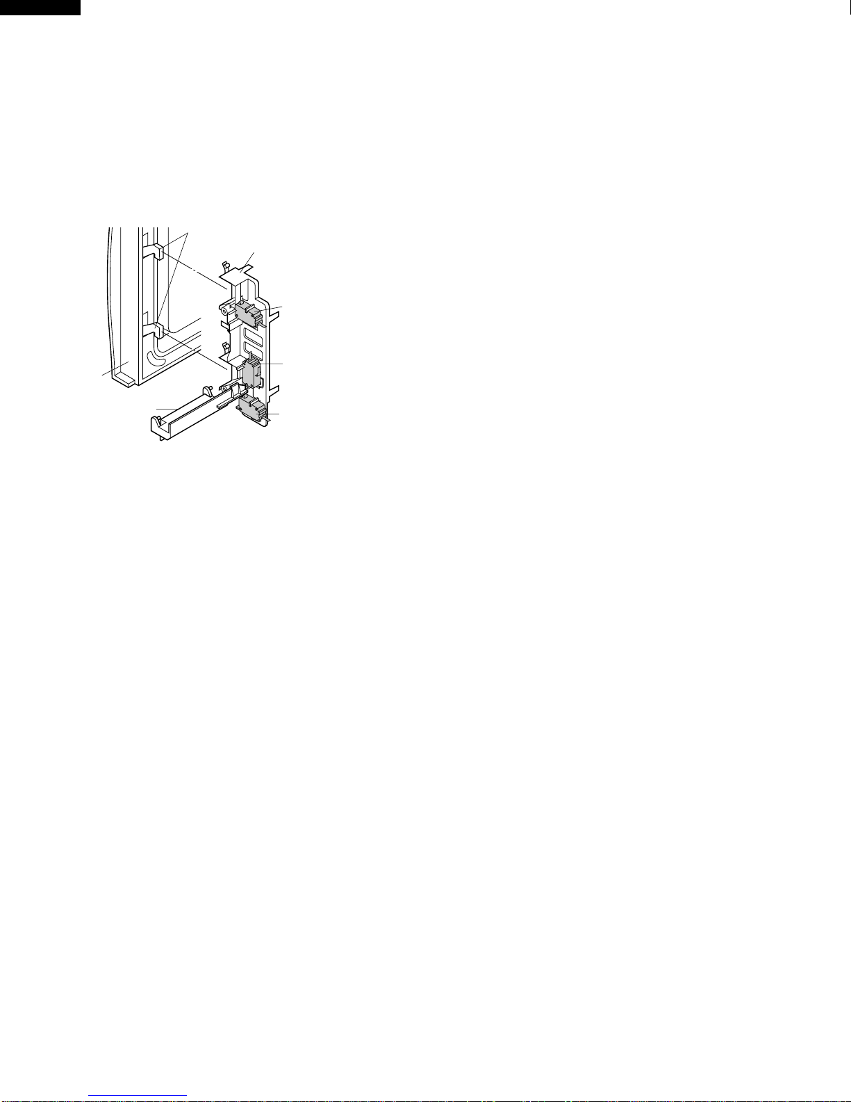
DOOR OPEN MECHANISM
The door is opened by pushing the open button on the
control panel, refer to the Figure D-1.
Whentheopenbuttonispushed,theopenbuttonpushesup
the switch lever, and then the switch lever pushes up the
latch head. The latch heads are moved upward and re-
leased from latch hook. Now the door will open.
Figure D-1. Door Open Mechanism
DOOR SENSING AND SECONDARY INTERLOCK
SWITCHES
The secondary interlock switch is mounted in the lower
positionofthelatchhookandthedoorsensing switchinthe
primaryinterlocksystemismountedintheupperpositionof
thelatchhook.Theyareactivatedbythelatch headsonthe
door. When the door is opened, the switches interrupt the
power to all high voltage components. A cook cycle cannot
take place until the door is firmly closed thereby activating
both interlock switches. The primary interlock system con-
sists of the door sensing switch and primary interlock relay
located on the control circuit board.
MONITOR SWITCH
Themonitorswitchisactivated(thecontactsopened)bythe
latch head on the door while the door is closed. The switch
is intended to render the oven inoperative, by means of
blowing the C/T fuse, when the contacts of the primary
interlock relay (RY2) and secondary interlock switch fail to
open when the door is opened.
Functions:
1. When the door is opened, the monitor switch contacts
close (to the ON condition) due to their being normally
closed.Atthistimetheprimaryinterlockrelay(RY2)and
secondary interlock switch are in the OFF condition
(contacts open) due to its being normally open contact
switches.
2. Asthedoorgoestoaclosedposition,themonitorswitch
contacts are first opened and then the door sensing
switch and secondary interlock switch contacts close.
3. If the door is opened, and the primary interlock relay
(RY2) and the secondary interlock switch contact fail to
open, the C/T fuse blows simultaneously with closing of
the monitor switch contacts.
CAUTION: BEFORE REPLACING A BLOWN C/T FUSE,
TEST THE DOOR SENSING SWITCH, PRI-
MARY INTERLOCK RELAY (RY2), SECOND-
ARY INTERLOCK SWITCH AND MONITOR
SWITCH FOR PROPER OPERATION. (RE-
FER TO CHAPTER "TEST PROCEDURE").
NOTE: C/T FUSE AND MONITOR SWITCH ARE
REPLACED AS AN ASSEMBLY.
TURNTABLE MOTOR
The turntable motor rotates the turntable located on the
bottom of the oven cavity, so that the food on the turntable
iscookedevenly. The turntable may turnineitherdirection.
COOLING FAN MOTOR
The cooling fan motor drives a blade which draws external
cool air. This cool air is directed through the air vents
surrounding the magnetron and cools the magnetron. This
air is channelled through the oven cavity to remove steam
and vapours given off from the heating foods. It is then
exhausted through the exhausting air vents at the oven
cavity.
TEMPERATURE FUSE (OVEN)
Thetemperaturefuse,locatedonthetopoftheovencavity,
isdesignedtopreventdamagetotheovenbyfire.Ifthefood
load is overcooked, by either error in cook time or defect in
the control unit, the temperature fuse will open.
Under normal operation, the temperature fuse remains
closed. However, when abnormally high temperatures are
reached within the oven cavity, the temperature fuse will
open at 248˚F(120˚C), causing the oven to shut down.
C/T FUSE
1. TheC/Tfuseblowswhenthe contacts (COM-NO)ofthe
primary interlock relay (RY2) and secondary interlock
switchremainclosedwiththe oven dooropenandwhen
the monitor switch closes.
2. If the wire harness or electrical components are short-
circuited,thisC/Tfuseblows topreventanelectricshock
or fire hazard.
3. The C/T fuse, located near the magnetron, is designed
to prevent damage to the magnetron. If an over heated
condition develops in the magnetron due to cooling fan
failure, obstructed air guide, dirty or blocked air intake,
etc., the C/T fuse will open.
Under normal operation, the C/T fuse remains closed.
However,whenabnormallyhightemperatures arereached
within the oven cavity, the C/T fuse will open at 248˚F
(120˚C),causingtheoventoshutdownorwhentheelectric
currents beyond 13A flow, the C/T fuse will open.
Latch Heads
Latch Hook
Door
Door
Sensing
Switch
Monitor
Switch
Switch Lever Secondary
Interlock
Switch

9
R-202EW
R-203EW
TROUBLESHOOTING GUIDE
Nevertouchanypartin the circuitwithyourhandoranuninsulated tool while thepowersupplyisconnected.
Whentroubleshootingthemicrowave oven,itishelpfultofollowthe SequenceofOperationinperformingthe checks.Many
ofthepossiblecausesoftroublewillrequirethataspecifictestbeperformed.Thesetestsaregivenaprocedureletterwhich
will be found in the "Test Procedure "section.
IMPORTANT: If the oven becomes inoperative because of a blown C/T fuse, check the monitor switch, primary
interlock relay (RY2), door sensing switch and secondary interlock switch before replacing the C/T fuse.
If C/T fuse is replaced, the monitor switch must also be replaced. Use part FFS-BA027WRKZ as an
assembly.
IMPORTANT: Whenever troubleshooting is performed with the power supply cord disconnected. It may in, some cases,
be necessary to connect the power supply cord after the outer case has been removed, in this event,
1. Disconnect the power supply cord, and then remove outer case.
2. Open the door and block it open.
3. Discharge high voltage capacitor.
4. Disconnect the leads to the primary of the power transformer.
5. Ensurethattheleadsremainisolatedfromothercomponents andovenchassisbyusinginsulation tape.
6. After that procedure, reconnect the power supply cord.
When the testing is completed,
1. Disconnect the power supply cord, and then remove outer case.
2. Open the door and block it open.
3. Discharge high voltage capacitor.
4. Reconnect the leads to the primary of the power transformer.
5. Reinstall the outer case (cabinet).
6. Reconnect the power supply cord after the outer case is installed.
7. Run the oven and check all functions.

10
R-202EW
R-203EW
AMAGNETRON ASSEMBLY TEST
1. Disconnect the power supply cord, and then remove outer case.
2. Open the door and block it open.
3. Discharge high voltage capacitor.
4. To test for an open filament, isolate the magnetron from the high voltage circuit. A continuity check
across the magnetron filament leads should indicate less than 1 ohm.
CK = Check / RE = Replace
TEST PROCEDURES
PROCEDURE
LETTER COMPONENT TEST
RECK AB C
D
EFFGHRE RE CK
I/K
CKCK CK J M L
SHORT IN POWER CORD
SHORT OR OPEN WIRING
MAGNETRON
POWER TRANSFORMER
H.V. RECTIFIER ASSEMBLY
HIGH VOLTAGE CAPACITOR
TEMPERATURE FUSE (OVEN)
PRIMARY INTERLOCK SYSTEM
SECONDARY INTERLOCK SWITCH
MONITOR SWITCH
C/T FUSE
OVEN LAMP OR SOCKET
COOLING FAN MOTOR
TURNTABLE MOTOR
CONTROL UNIT OR RELAY
WRONG OPERATION
LOW VOLTAGE
DIRTY OVEN CAVITY
KEY UNIT
FOIL PATTERN ON PWB.
EXPRESS DEFROST
Home fuse blows when power cord
is plugged into wall receptacle.
C/T fuse blows when power cord is
plugged into wall receptacle.
Any letters or indicators do not ap-
pear in display when power cord is
first plugged into wall outlet.
Display does not operate properly
whenSTOP/CLEARkey istouched.
(Buzzer should sound and time of
day should appear in display.)
C/T fuse blows when the door is
opened.
Fan motor does not operate. (All
otherelectriccomponentsfunction.)
Oven lamp does not light at all. (All
otherelectriccomponentsfunction.)
Turntablemotordoesnot operate. (All
other electric components function.)
Oven does not go into cook cycle
when START pad is touched
Ovenseemstobeoperatingbutlittle
or no heat is produced in oven load.
(Food incompletely cooked or not
cooked at all at end of cook cycle.)
Oven goes into a cook cycle but
extremely uneven heating is pro-
duced in oven load (food).
Oven does not cook properly when
programmed for Cooking Power 5
mode. (Operates properly on Cook-
ing Power 10 (HIGH) mode.)
Oven lamp, turntable motor and fan
motor do not operate.
OvengoesintoEXPRESSDEFROST
but food is not defrosted well.
TEST PROCEDURE
PROBLEM
CONDITION
OFF
CONDITION
COOKING
CONDITION
POSSIBLE CAUSE
AND
DEFECTIVE PARTS

11
R-202EW
R-203EW
BPOWER TRANSFORMER TEST
1. Disconnect the power supply cord, and then remove outer case.
2. Open the door and block it open.
3. Discharge high voltage capacitor.
4. Disconnect the primary input terminals and measure the resistance of the transformer with an
ohmmeter. Check for continuity of the coils with an ohmmeter. On the R x 1 scale, the resistance of
the primary coil should be less than 1 ohm and the resistance of the high voltage coil should be
approximately 185 ohms; the resistance of the filament coil should be less than 1 ohm.
5. Reconnect all leads removed from components during testing.
6. Reinstall the outer case (cabinet).
7. Reconnect the power supply cord after the outer case is installed.
8. Run the oven and check all functions.
(HIGHVOLTAGESAREPRESENTATTHE HIGH VOLTAGETERMINAL,SODONOTATTEMPTTO
MEASURE THE FILAMENT AND HIGH VOLTAGE.)
TEST PROCEDURES
PROCEDURE
LETTER COMPONENT TEST
5. Totestforashortedmagnetron,connecttheohmmeterleadsbetweenthemagnetronfilamentleads
and chassis ground. This test should indicate an infinite resistance. If there is little or no resistance
the magnetron is grounded and must be replaced.
6. Reconnect all leads removed from components during testing.
7. Reinstall the outer case (cabinet).
8. Reconnect the power supply cord after the outer case is installed.
9. Run the oven and check all functions.
MICROWAVE OUTPUT POWER
The following test procedure should be carried out with the microwave oven in a fully assembled
condition (outer case fitted).
HIGH VOLTAGES ARE PRESENT DURING THE COOK CYCLE, SO EXTREME CAUTION SHOULD
BE OBSERVED.
Power output of the magnetron can be measured by performing a water temperature rise test. This test
shouldonlybeusedifabovetestsdonotindicateafaultymagnetronandthereisnodefectinthefollowing
componentsorwiring:siliconrectifier,highvoltagecapacitorandpowertransformer.Thistestwillrequire
a 16 ounce (453cc) measuring cup and an accurate mercury thermometer or thermocouple type
temperature tester. For accurate results, the following procedure must be followed carefully:
1. Fillthemeasuringcupwith16oz.(453cc)oftapwaterandmeasurethetemperatureofthewaterwith
a thermometer or thermocouple temperature tester. Stir the thermometer or thermocouple through
the water until the temperature stabilizes. Record the temperature of the water.
2. Place the cup of water in the oven. Operate oven at P-HI (100% Power) selecting more than 60
secondscooktime.Allowthewatertoheatfor60seconds,measuringwithastopwatch,secondhand
of a watch or the digital read-out countdown.
3. Remove the cup from the oven and again measure the temperature, making sure to stir the
thermometer or thermocouple through the water until the maximum temperature is recorded.
4. Subtractthecoldwatertemperaturefromthe hot water temperature. The normal resultshouldbe18
to 33˚F(10 to 18.3˚C) rise in temperature. If the water temperatures are accurately measured and
tested for the required time period the test results will indicate if the magnetron tube has low power
output (low rise in water temperature) which would extend cooking time or high power output (high
risein water temperature) which wouldreduce cooking time.Because cooking timecan be adjusted
to compensate for power output, the magnetron tube assembly should be replaced only if the water
temperaturerisetestindicatesapoweroutputwellbeyondthenormallimits.Thetestisonlyaccurate
if the power supply line voltage is 120 volts and the oven cavity is clean.

12
R-202EW
R-203EW
TEST PROCEDURES
PROCEDURE
LETTER COMPONENT TEST
1. Disconnect the power supply cord, and then remove outer case.
2. Open the door and block it open.
3. Discharge high voltage capacitor.
4. If the capacitor is open, no high voltage will be available to the magnetron. Disconnect input leads
and check for short or open between the terminals using an ohmmeter.
Checking with a high ohm scale, if the high voltage capacitor is normal, the meter will indicate
continuity for a short time and should indicate an open circuit once the capacitor is charged. If the
above is not the case, check the capacitor with an ohmmeter to see if it is shorted between either of
the terminals and case. If it is shorted, replace the capacitor.
5. Reconnect all leads removed from components during testing.
6. Reinstall the outer case (cabinet).
7. Reconnect the power supply cord after the outer case is installed.
8. Run the oven and check all functions.
DHIGH VOLTAGE CAPACITOR TEST
ETEMPERATURE FUSE TEST
1. Disconnect the power supply cord, and then remove outer case.
2. Open the door and block it open.
3. Discharge high voltage capacitor.
4. A continuity check across the temperature fuse terminals should indicate a closed circuit unless the
temperature of the temperature fuse reaches approximately 248˚F(120˚C).
An open temperature fuse indicates overheating of the oven, exchange the temperature fuse and
checkinsideofovencavityandforimpropersettingofcookingtimeoroperationofcontrolunit.Check
forrestrictedairflowthroughtheventholesoftheovencavity,especiallythecoolingfanandairguide.
5. Reconnect all leads removed from components during testing.
6. Reinstall the outer case (cabinet).
7. Reconnect the power supply cord after the outer case is installed.
8. Run the oven and check all functions.
CHIGH VOLTAGE RECTIFIER TEST
1. Disconnect the power supply cord, and then remove outer case.
2. Open the door and block it open.
3. Discharge high voltage capacitor.
4. Isolate the rectifier from the circuit. Using the highest ohm scale of the meter, read the resistance
across the terminals and observe, reverse the leads to the rectifier terminals and observe meter
reading. If a short is indicated in both directions, or if an infinite resistance is read in both directions,
the rectifier is probably defective and should be replaced.
5. Reconnect all leads removed from components during testing.
6. Reinstall the outer case (cabinet).
7. Reconnect the power supply cord after the outer case is installed.
8. Run the oven and check all functions.
NOTE:Besure to use anohmmeterthat will supply aforwardbias voltage of morethan6.3volts.
FSECONDARY INTERLOCK SWITCH TEST
1. Disconnect the power supply cord, and then remove outer case.
2. Open the door and block it open.
3. Discharge high voltage capacitor.
4. Isolatetheswitchandconnecttheohmmetertothecommon(COM.)andnormallyopen(NO)terminal
of the switch. The meter should indicate an open circuit with the door open and a closed circuit with
the door closed. If improper operation is indicated, replace the secondary interlock switch.
5. Reconnect all leads removed from components during testing.
6. Reinstall the outer case (cabinet).
7. Reconnect the power supply cord after the outer case is installed.

13
R-202EW
R-203EW
TEST PROCEDURES
PROCEDURE
LETTER COMPONENT TEST
1. Disconnect the power supply cord, and then remove outer case.
2. Open the door and block it open.
3. Discharge high voltage capacitor.
4. Before performing this test, make sure that the secondary interlock switch and the primary interlock
relayareoperatingproperly,accordingtotheaboveSwitchTestProcedure.Disconnectthewirelead
fromthe monitor switch(COM)terminal. Check themonitorswitch operation byusingthe ohmmeter
asfollows.Whenthedoorisopen,themetershouldindicateaclosedcircuit.Whenthemonitorswitch
actuatoris pushed byascrew driver throughthe lower latch holeon the frontplateof the ovencavity
withthedooropened(inthisconditiontheplungerofthemonitorswitchispushedin),themetershould
indicate an open circuit. If improper operation is indicated, the switch may be defective. After testing
the monitor switch, reconnect the wire lead to the monitor switch (COM) terminal and check the
continuity of the monitor circuit.
5. Reconnect all leads removed from components during testing.
6. Reinstall the outer case (cabinet).
7. Reconnect the power supply cord after the outer case is installed.
8. Run the oven and check all functions.
PRIMARY INTERLOCK SYSTEM TEST
DOOR SENSING SWITCH
1. Disconnect the power supply cord, and then remove outer case.
2. Open the door and block it open.
3. Discharge high voltage capacitor.
4. Isolatetheswitchandconnecttheohmmetertothecommon(COM.)andnormallyopen(NO)terminal
of the switch. The meter should indicate an open circuit with the door open and a closed circuit with
the door closed. If improper operation is indicated, replace the door sensing switch.
5. Reconnect all leads removed from components during testing.
6. Reinstall the outer case (cabinet).
7. Reconnect the power supply cord after the outer case is installed.
8. Run the oven and check all functions.
PRIMARY INTERLOCK RELAY (RY2)
1. Disconnect the power supply cord, and then remove outer case.
2. Open the door and block it open.
3. Discharge high voltage capacitor.
4. Disconnect two (2) wire leads from the male tab terminals of the Primary Interlock Relay. Check the
stateoftherelaycontactsusingaohmmeter.Therelaycontactsshouldbeopen.Iftherelaycontacts
are closed, replace the circuit board entirely or the relay itself.
5. Reconnect all leads removed from components during testing.
6. Reinstall the outer case (cabinet).
7. Reconnect the power supply cord after the outer case is installed.
8. Run the oven and check all functions.
GMONITOR SWITCH TEST
SCREW
DRIVER RED GRY
GRY
MONITOR
SWITCH
OHMMETER

14
R-202EW
R-203EW
HBLOWN C/T FUSE TEST
TEST PROCEDURES
PROCEDURE
LETTER COMPONENT TEST
1. Disconnect the power supply cord, and then remove outer case.
2. Open the door and block it open.
3. Discharge high voltage capacitor.
4. IftheC/Tfuseisblownwhenthedoorisopened,checktheprimaryinterlockrelay,secondaryinterlock
switchandmonitorswitchaccordingtothe"TESTPROCEDURE"forthoseswitchesbeforereplacing
the blown C/T fuse.
CAUTION: BEFORE REPLACING A BLOWN C/T FUSE, TEST THE PRIMARY INTERLOCK RELAY,
SECONDARYINTERLOCKSWITCH,DOORSENSINGSWITCHANDMONITORSWITCH
FOR PROPER OPERATION.
If the C/T fuse is blown by improper switch operation, the C/T fuse and monitor switch must be
replaced with "C/T fuse and monitor switch assembly" part number FFS-BA027WRKZ, even if the
monitor switch operates normally. The C/T fuse and monitor switch assembly is comprised of a 13
ampere fuse and switch.
AcontinuitycheckacrosstheC/Tfuseterminalsshouldindicateaclosedcircuitunlessthetemperature
of the C/T fuse reaches approximately 248˚F(120˚C).
AnopenC/Tfuseindicatesoverheatingofthemagnetron.Checkforrestrictedairflowtothemagnetron,
especially the cooling fa air guide.
CAUTION: IFTHEC/TFUSEINDICATESANOPENCIRCUITATROOMTEMPERATURE,REPLACE
THE C/T FUSE.
5. Reconnect all leads removed from components during testing.
6. Reinstall the outer case (cabinet).
7. Reconnect the power supply cord after the outer case is installed.
8. Run the oven and check all functions.
The touch control panel consists of circuits including semiconductors such as LSI, ICs, etc. Therefore,
unlike conventional microwave ovens, proper maintenance cannot be performed with only a voltmeter
and ohmmeter.
In this service manual, the touch control panel assembly is divided into two units, Control Unit and Key
Unit, and troubleshooting by unit replacement is described according to the symptoms indicated.
Before testing,
1) Disconnect the power supply cord and then remove outer case.
2) Open the door and block it open.
3) Discharge high voltage capacitor.
4) Disconnect the leads to the primary of the power transformer.
5) Ensure that these leads remain isolated from other components and oven chassis by using
insulation tape.
6) After that procedure, re-connect the power supply cord.
1. Key Unit.
NOTE ;
1) Disconnect the power supply cord and then remove outer case.
2) Open the door and block it open.
3) Discharge high voltage capacitor.
4) Check key unit ribbon connection before replacement.
5) Reconnect all leads removed from components during testing.
6) Re-install the outer case (cabinet).
7) Reconnect the power supply cord after the outer case is installed.
8) Run the oven and check all functions.
The following symptoms indicate a defective key unit.
a) When touching the pads, a certain pad produces no signal at all.
b) When touching a number pad, two figures or more are displayed.
c) When touching the pads, sometimes a pad produces no signal.
ITOUCH CONTROL PANEL ASSEMBLY TEST

15
R-202EW
R-203EW
If the key unit is defective.
1) Disconnect the power supply cord and then remove outer case.
2) Open the door and block it open.
3) Discharge high voltage capacitor.
4) Replace the key unit.
5) Reconnect all leads removed from components during testing.
6) Re-install the outer case (cabinet).
7) Reconnect the power supply cord after the outer case is installed.
8) Run the oven and check all functions.
2. Control Unit.
The following symptoms indicate a defective control unit. Before replacing the control unit, perform
the Key unit test (Procedure J) to determine if control unit is faulty.
2-1 In connection with pads.
a) When touching the pads, a certain group of pads do not produce a signal.
b) When touching the pads, no pads produce a signal.
2-2 In connection with indicators
a) At a certain digit, all or some segments do not light up.
b) At a certain digit, brightness is low.
c) Only one indicator does not light.
d) The corresponding segments of all digits do not light up; or they continue to light up.
e) Wrong figure appears.
f) A certain group of indicators do not light up.
g) The figure of all digits flicker.
2-3 Other possible problems caused by defective control unit.
a) Buzzer does not sound or continues to sound.
b) Clock does not operate properly.
c) Cooking is not possible.
When testing is completed,
1) Disconnect the power supply cord and then remove outer case.
2) Open the door and block it open.
3) Discharge high voltage capacitor.
4) Reconnect all leads removed from components during testing.
5) Re-install the outer case (cabinet).
6) Reconnect the power supply cord after the outer case is installed.
7) Run the oven and check all functions.
TEST PROCEDURES
PROCEDURE
LETTER COMPONENT TEST
JKEY UNIT TEST
1. Disconnect the power supply cord and then remove outer case.
2. Open the door and block it open.
3. Discharge high voltage capacitor.
4. If the display fails to clear when the STOP/CLEAR pad is depressed, first verify the flat ribbon cable
ismakinggoodcontact,verifythatthedoorsensingswitch(stopswitch)operatesproperly;thatisthe
contacts are closed when the door is closed and open when the door is open. If the door sensing
switch (stop switch) is good, disconnect the flat ribbon cable that connects the key unit to the control
unitandmake sure the doorsensingswitchis closed (either closethedooror short the doorsensing
switch connecter). Use the Key unit matrix indicated on the control panel schematic and place a
jumperwirebetweenthepinsthatcorrespondtotheSTOP/CLEARpadmakingmomentarycontact.
If the control unit responds by clearing with a beep, the key unit is faulty and must be replaced. If the
control unit does not respond, it is faulty and must be replaced. If a specific pad does not respond,
the above method may be used (after clearing the control unit) to determine if the control unit or key
pad is at fault.
5. Reconnect all leads removed from components during testing.
6. Re-install the outer case (cabinet).
7. Reconnect the power supply cord after the outer case is installed.
8. Run the oven and check all functions.

16
R-202EW
R-203EW
(1) Place one cup of water in the center of the turntable tray in the oven cavity.
(2) Close the door, touch the " EXPRESS DEFROST " pad once.
(3) The oven is in Express Defrost cooking condition.
(4) The oven will operate as follows.
MENU 1ST STAGE 2ND STAGE 3RD STAGE 4TH STAGE
EXPRESS DEFROST LEVEL TIME LEVEL TIME LEVEL TIME LEVEL TIME
0.5lb 70% 1min.9sec. 0% 56sec. 50% 42sec. 30% 45sec.
(5) If improper operation is indicated, the control unit is probably defective and should be checked.
TEST PROCEDURES
PROCEDURE
LETTER COMPONENT TEST
1. Disconnect the power supply cord and then remove outer case.
2. Open the door and blocked it open.
3. Discharge high voltage capacitor.
4. Disconnect the leads to the primary of the power transformer.
5. Ensurethattheseleadsremainisolatedfromothercomponentsandovenchassisbyusinginsulation
tape.
6. After that procedure, re-connect the power supply cord.
7. RemovetheoutercaseandcheckvoltagebetweenPinNo.3ofthe2pinconnector(A)andthenormal
open terminal of the relay RY2 on the control unit with an A.C. voltmeter.
The meter should indicate 120 volts, if not check oven circuit.
RY1 and RY2 Relay Test
These relays are operated by D.C. voltage
Check voltage at the relay coil with a D.C. voltmeter during the microwave cooking operation.
DC. voltage indicated..........................Defective relay.
DC. voltage not indicated....................Check diode which is connected to the relay coil. If diode
is good, control unit is defective.
RELAY SYMBOL OPERATIONAL VOLTAGE CONNECTED COMPONENTS
RY1 Approx. 12.0V D.C. Oven lamp / Turntable motor / Cooling fan motor
RY2 Approx. 12.0V D.C. Power transformer
8. If any abnormal condition is defected, replace the control unit.
9. Disconnect the power supply cord and then remove outer case.
10. Open the door and block it open.
11. Discharge high voltage capacitor.
12. Reconnect all leads removed from components during testing.
13. Re-install the outer case (cabinet).
14. Reconnect the power supply cord after the outer case is installed.
15. Run the oven and check all functions.
KRELAY TEST
L EXPRESS DEFROST TEST
1
2
345
6
7
89
0
POWER
LEVEL
MINUTE
PLUS
REHEAT
BEVERAGE
BAKED
POTATOES
EXPRESS
DEFROST
POPCORN START
ROLLS
MUFFINS
FRESH
VEGETABLES
TIMER
CLOCK
G 1 G 2 G 3 G 4 G 5 G 6
G 7
G 8
G 9
G10
STOP
CLEAR

17
R-202EW
R-203EW
TEST PROCEDURES
PROCEDURE
LETTER COMPONENT TEST
To protect the electronic circuits, this model is provided with a fine foil pattern added to the primary on
the PWB, this foil pattern acts as a fuse.
1. Foil pattern check and repairs.
1) Disconnect the power supply cord and then remove outer case.
2) Open the door and block it open.
3) Discharge high voltage capacitor.
4) Follow the troubleshooting guide given below for repair.
STEPS OCCURRENCE CAUSE OR CORRECTION
1 Only pattern at "a" is broken. *Insert jumper wire J1 and solder.
2 Pattern at "a" and "b" are broken. *Insert the coil RCILF2003YAZZ between "c" and "d".
5) Make a visual inspection of the varistor.
Checkforburneddamageandexamine
the transformer with a tester for the
presence of layer short-circuit (check
the primary coil resistance which is
approximately 563Ω±10%). If any
abnormalconditionisdetected,replace
the defective parts.
6) Reconnect all leads removed from components during testing.
7) Re-install the outer case (cabinet).
8) Reconnect the power supply cord after the outer case is installed.
9) Run the oven and check all functions.
2. Follow the troubleshooting guide given below, if indicator does not light up after above check and
repairs are finished.
1) Disconnect the power supply cord and then remove outer case.
2) Open the door and block it open.
3) Discharge high voltage capacitor.
4) Disconnect the leads to the primary of the power transformer.
5) Ensure that these leads remain isolated from other components and oven chassis by using
insulation tape.
6) After that procedure, re-connect the power supply cord.
7) Follow the troubleshooting guide given below for repair.
STEPS OCCURRENCE CAUSE OR CORRECTION
The rated AC voltage is not present between
1 Pin No. 3 of the 2-pin connector (A) and the Check supply voltage and oven power cord.
common terminal of the relay RY2.
2 The rated AC voltage is present at primary Low voltage transformer or secondary circuit defective.
side of low voltage transformer. Check and replace control unit.
8) Disconnect the power supply cord and then remove outer case.
9) Open the door and block it open.
10) Discharge high voltage capacitor.
11) Reconnect all leads removed from components during testing.
12) Re-install the outer case (cabinet).
13) Reconnect the power supply cord after the outer case is installed.
14) Run the oven and check all functions.
M FOIL PATTERN ON THE PRINTED WIRING BOARD TEST
CN-A
J1
a
bc
d
RY1
VRS1
1
3

18
R-202EW
R-203EW
The touch control section consists of the following units as
shown in the touch control panel circuit.
(1) Key Unit
(2) Control Unit
The principal functions of these units and their related
signals are explained below.
Key Unit
The key unit is composed of a matrix, signals generated in
theLSIaresenttothekeyunitthroughR00,R01,R02,R03,
R20 and R21.
When a key pad is touched, a signal is completed through
the key unit and passed back to the LSI through R23, K00,
K01 and K02 to perform the function that was requested.
Control Unit
Control unit consists of LSI, ACL circuit, indicator circuit,
power source circuit, relay circuit, buzzer circuit and syn-
chronizing signal circuit.
1) ACL
ThiscircuitgeneratesasignalwhichresetstheLSItothe
initial state when power is supplied.
2) Indicator Circuit
This circuit consists of 4-digits, 12-segments and 3-
common electrodes using a Liquid Crystal Display.
TOUCH CONTROL PANEL ASSEMBLY
OUTLINE OF TOUCH CONTROL PANEL
3) Power Source Circuit
This circuit generates voltage necessary in the control
unitfromtheAClinevoltage.Inaddition,thesynchronizing
signal is available in order to compose a basic standard
time in the clock circuit.
Symbol Voltage Application
VC -5V LSI(IC1)
4) Relay Circuit
To drive the magnetron, fan motor, turntable motor and
light the oven lamp.
5) Buzzer Circuit
The buzzer is responsive to signals from the LSI to emit
audiblesounds(keytouchsoundandcompletionsound).
6) Synchronizing Signal Circuit
The power source synchronizing signal is available in
order to compose a basic standard time in the clock
circuit. It accompanies a very small error because it
works on commercial frequency.
7) 2nd. Interlock Relay Control Switch (Door Sensing
Switch)
A switch to “tell”the LSI if the door is open or closed.
This manual suits for next models
1
Table of contents
Other Sharp Microwave Oven manuals

Sharp
Sharp R-610DKA User manual

Sharp
Sharp Carousel R-203HW User manual

Sharp
Sharp R-408EW User manual

Sharp
Sharp R-395F(S) User manual

Sharp
Sharp R-244M Instruction Manual

Sharp
Sharp R-204 Instruction Manual

Sharp
Sharp Carousel R-312AK User manual

Sharp
Sharp R-4H56 User manual

Sharp
Sharp Carousel R-1874 User manual

Sharp
Sharp R-830B User manual

Sharp
Sharp R-959(SL)M-AA User manual

Sharp
Sharp R-980J User manual

Sharp
Sharp Carousel R-480E User manual

Sharp
Sharp R-259 Instruction Manual

Sharp
Sharp R-871 User manual

Sharp
Sharp R-1880LST User manual

Sharp
Sharp R-3H57 User manual

Sharp
Sharp R-420D User manual

Sharp
Sharp Carousel R-395Y User manual

Sharp
Sharp R-216(G) User manual