Sharp R-409EW User manual

R-409EW
R-410EK
R-410EW
Intheinterestofuser-safetytheovenshouldberestoredtoitsoriginal
condition and only parts identical to those specified should be used.
WARNING TO SERVICE PERSONNEL: Microwave ovens con-
tain circuitry capable of producing very high voltage and
current, contact with following parts may result in a severe,
possibly fatal, electrical shock. (High Voltage Capacitor, High
Voltage Power Transformer, Magnetron, High Voltage Recti-
fier Assembly, High Voltage Harness etc..)
TABLEOFCONTENTS Page
PRECAUTIONS TO BE OBSERVED BEFORE AND DURING SERVICING TO
AVOID POSSIBLE EXPOSURE TO EXCESSIVE MICROWAVE ENERGY.................. INSIDE FRONT COVER
BEFORE SERVICING..................................................................................................... INSIDE FRONT COVER
WARNING TO SERVICE PERSONNEL .............................................................................................................. 1
MICROWAVE MEASUREMENT PROCEDURE .................................................................................................. 2
FOREWORD AND WARNING............................................................................................................................. 3
PRODUCT SPECIFICATIONS............................................................................................................................. 4
GENERAL INFORMATION ................................................................................................................................. 4
OPERATION ........................................................................................................................................................ 6
TROUBLESHOOTING GUIDE............................................................................................................................. 9
TEST PROCEDURE ...........................................................................................................................................10
TOUCH CONTROL PANEL ................................................................................................................................18
COMPONENT REPLACEMENT AND ADJUSTMENT PROCEDURE................................................................22
PICTORIAL DIAGRAM .......................................................................................................................................28
POWER UNIT CIRCUIT......................................................................................................................................29
CPU UNIT CIRCUIT............................................................................................................................................30
PRINTED WIRING BOARD ................................................................................................................................31
PARTS LIST........................................................................................................................................................33
PACKINGANDACCESSORIES .........................................................................................................................37
S21M160R409EE
R-409EW
R-410EK
R-410EW
MICROWAVEOVEN
MODELS
SERVICE MANUAL
R-409EW
SHARP ELECTRONCS CORPORATION This document has been published to be used for after
sales service only.
The contents are subject to change without notice.
Service Headquarters: Sharp Plaza, Mahwah, New Jersey, 07430-2135
R-410EK

R-409EW
R-410EK
R-410EW
PRECAUTIONSTO BE OBSERVED BEFORE AND
DURING SERVICING TO AVOID POSSIBLE
EXPOSURE TO EXCESSIVE MICROWAVE
ENERGY
(a) Do notoperate or allowthe oven tobe operated withthe door open.
(b) Make the following safety checks on all ovens to be serviced before activating the magnetron or other
microwavesource,andmake repairs as necessary: (1) interlockoperation,(2)properdoorclosing,(3)
sealandsealingsurfaces (arcing, wear, and other damage),(4)damagetoorloosening of hinges and
latches,(5) evidence of dropping orabuse.
(c) Beforeturning on microwavepowerfor any servicetest or inspection withinthe microwave generating
compartments, check the magnetron, wave guide or transmission line, and cavity for proper alignment,
integrity,and connections.
(d) Any defective or misadjusted components in the interlock, monitor, door seal, and microwave generation
and transmission systems shall be repaired, replaced, or adjusted by procedures described in this
manualbefore the ovenis released tothe owner.
(e) A microwave leakage check to verify compliance with the Federal Performance Standard should be
performedoneachovenpriorto release to the owner.
BEFORE SERVICING
Before servicing an operative unit, perform a microwave emission check as per the
Microwave Measurement Procedure outlined in this service manual.
If microwave emissions level is in excess of the specified limit, contact SHARP
ELECTRONICSCORPORATIONimmediately @1-800-237-4277.
If the unit operates with the door open, service person should 1) tell the user
not to operate the oven and 2) contact SHARP ELECTRONICS CORPORATION and Food and
Drug Administration's Center for Devices and Radiological Health immediately.
Service personnel should inform SHARP ELECTRONICS CORPORATION of any certified unit
found with emissions in excess of 4mW/cm2. The owner of the unit should be instructed
not to use the unit until the oven has been brought into compliance.

1
R-409EW
R-410EK
R-410EW
WARNING TO SERVICE PERSONNEL
Microwave ovens contain circuitry capable of pro-
ducing very high voltage and current, contact with
following parts
may result in a severe, possibly
fatal, electrical shock.
(Example)
HighVoltageCapacitor,HighVoltagePowerTrans-
former,Magnetron,HighVoltageRectifierAssem-
bly, High Voltage Harness etc..
Read the Service Manual carefully and follow all
instructions.
Before Servicing
1. Disconnect the power supply cord , and then
remove outer case.
2. Open the door and block it open.
3. Discharge high voltage capacitor.
WARNING:RISK OF ELECTRIC SHOCK.
DISCHARGE THE HIGH-VOLTAGE
CAPACITOR BEFORE SERVICING.
The high-voltage capacitor remains charged about 60
secondsaftertheovenhasbeenswitchedoff.Waitfor60
secondsandthenshort-circuittheconnectionofthehigh-
voltagecapacitor(thatistheconnectingleadofthehigh-
voltage rectifier) against the chassis with the use of an
insulated screwdriver.
Whenever troubleshooting is performed the power supply
mustbedisconnected.Itmay,in somecases,benecessary
to connect the power supply after the outer case has been
removed, in this event:
1. Disconnect the power supply cord, and then remove
outer case.
2. Open the door and block it open.
3. Discharge high voltage capacitor.
4. Disconnect the leads to the primary of the power
transformer.
5. Ensure that the leads remain isolated from other
components and oven chassis by using insulation tape.
6. After that procedure, reconnect the power supply cord.
When the testing is completed,
1. Disconnect the power supply cord, and then remove
outer case.
2. Open the door and block it open.
3. Discharge high voltage capacitor.
4. Reconnect the leads to the primary of the power
transformer.
5. Reinstall the outer case (cabinet).
6. Reconnectthepower supply cord after theoutercase is
installed.
7. Run the oven and check all functions.
After repairing
1. Reconnect all leads removed from components during
testing.
2. Reinstall the outer case (cabinet).
3. Reconnectthepower supply cord after theoutercase is
installed.
4. Run the oven and check all functions.
Microwaveovensshouldnotbeoperatedempty.To testfor
the presence of microwave energy within a cavity, place a
cup of cold water on the oven turntable, close the door and
set the power to HIGH and set the microwave timer for two
(2) minutes. When the two minutes has elapsed (timer at
zero) carefully check that the water is now hot. If the water
remainscoldcarryoutBeforeServicingprocedureandre-
examine the connections to the component being tested.
When all service work is completed and the oven is fully
assembled,themicrowavepoweroutputshouldbechecked
and a microwave leakage test should be carried out.
Don't Touch !
Danger High Voltage

2
R-409EW
R-410EK
R-410EW MICROWAVE MEASUREMENT PROCEDURE
A. Requirements:
1) Microwave leakage limit (Power density limit): The power density of microwave radiation emitted by a microwave oven
shouldnotexceed1mW/cm2atanypoint5cmormorefromtheexternalsurfaceoftheoven,measuredpriortoacquisition
byapurchaser,andthereafter(throughthe useful lifeoftheoven),5mW/cm2atanypoint5cmor more fromtheexternal
surface of the oven.
2) Safetyinterlockswitches, primary interlock relayanddoorsensing switch shall preventmicrowaveradiationemission in
excess of the requirement as above mentioned. Secondary interlock switch shall prevent microwave radiation emission
in excess of 5 mW/cm2at any point 5cm or more from the external surface of the oven.
B. Preparation for testing:
Before beginning the actual measurement of leakage, proceed as follows:
1) Make sure that the actual instrument is operating normally as specified in its instruction booklet.
Important:
Survey instruments that comply with the requirement for instrumentation as prescribed by the performance standard for
microwave ovens, 21 CFR 1030.10(c)(3)(i), must be used for testing.
2) Place the oven tray in the oven cavity.
3) Place the load of 275±15 ml (9.8 oz) of tap water initially at 20±5O
C (68OF) in the center of the oven cavity.
Thewatercontainershallbe alowformof600ml(20oz) beakerwithaninsidediameterofapprox.8.5 cm(3-1/2in.)and
made of an electrically nonconductive material such as glass or plastic.
Theplacing of this standardloadin the ovenisimportant not only toprotectthe oven, but alsoto insure that anyleakage
is measured accurately.
4) Set the cooking control on Full Power Cooking Mode.
5) Closethedoorandselectacookcycleofseveralminutes.Ifthewaterbeginstoboilbeforethesurveyiscompleted,replace
it with 275 ml of cool water.
C. Leakage test:
Closed-door leakage test (microwave measurement):
1) Grasptheprobeofthesurveyinstrumentandholditperpendiculartothegapbetweenthedoorandthebodyoftheoven.
2) Movetheprobeslowly,notfasterthan1in./sec.(2.5cm/sec.)alongthegap,watchingforthemaximumindicationonthe
meter.
3) Checkforleakageatthedoorscreen,sheetmetalseamsandotheraccessiblepositionswherethecontinuityofthemetal
has been breached (eg., around the switches, indicator, and vents).
Whiletestingforleakagearoundthedoor,pullthedoorawayfromthefrontoftheovenasfarasispermittedbytheclosed
latch assembly.
4) Measure carefully at the point of highest leakage and make sure that the highest leakage is no greater than 4mW/cm2,
and that the secondary interlock switch does turn the oven OFF before any door movement.
NOTE: After servicing, record data on service invoice and microwave leakage report.

3
R-409EW
R-410EK
R-410EW
SHARP ELECTRONICS CORPORATION
SHARP PLAZA, MAHWAH,
NEW JERSEY 07430-2135
SERVICE MANUAL
MICROWAVE OVEN
R-409EW/R-410EK/R-410EW
FOREWORD
This Manual has been prepared to provide Sharp Electronics Corp.
ServicePersonnelwithOperationandServiceInformationfortheSHARP
MICROWAVEOVENS,R-409EW,R-410EK,R-410EW.
It is recommended that service personnel carefully study the entire text
ofthismanualsothattheywillbequalifiedtorendersatisfactorycustomer
service.
Checktheinterlockswitchesandthedoorsealcarefully.Specialattention
shouldbegiventoavoidelectricalshockandmicrowaveradiationhazard.
WARNING
Never operate the oven until the following points are ensured:
(A) The door is tightly closed.
(B) The door brackets and hinges are not defective.
(C) The door packing is not damaged.
(D) The door is not deformed or warped.
(E) There is no other visible damage with the oven.
Servicing and repair work must be carried out only by trained service
personnel. DANGER
Certain initial parts are intentionally not grounded and present
ariskof electricalshockonly duringservicing.Service person-
nel - Do not contact the following parts while the appliance is
energized;
High Voltage Capacitor, Power Transformer, Magnetron, High
Voltage Rectifier Assembly, High Voltage Harness;
If provided, Vent Hood, Fan assembly, Cooling Fan Motor.
All the parts marked “*” on parts list are used at voltages more than
250V.
Removal of the outer wrap gives access to voltage above 250V.
All the parts marked “∆” on parts list may cause undue microwave
exposure, by themselves, or when they are damaged, loosened or
removed.
PRODUCTDESCRIPTION
GENERALINFORMATION
OPERATION
TROUBLESHOOTINGGUIDEAND
TESTPROCEDURE
TOUCHCONTROLPANEL
COMPONENTREPLACEMENT
ANDADJUSTMENTPROCEDURE
WIRINGDIAGRAM
PARTS LIST

4
R-409EW
R-410EK
R-410EW
GENERAL INFORMATION
GROUNDING INSTRUCTIONS
This oven is equipped with a three prong grounding plug. It must be plugged into a wall receptacle that is properly installed
and grounded in accordance with the National Electrical Code and local codes and ordinances.
Intheeventofanelectricalshortcircuit,groundingreducestheriskofelectricshockbyprovidinganescapewirefortheelectric
current.
WARNING: Improper use of the grounding plug can result in a risk of electric shock.
ElectricalRequirements
The electrical requirements are a 120 volt 60 Hz, AC only,
15or20amp.fusedelectricalsupply.Itisrecommendedthataseparatecircuitservingonlythisappliancebeprovided.When
installing this appliance, observe all applicable codes and ordinances.
A short power-supply cord is provided to reduce risks of becoming entangled in or tripping over a longer cord.
Whereatwo-prongedwall-receptacleisencountered,itisthepersonalresponsibilityandobligationofthecustomertocontact
SPECIFICATION
ITEM DESCRIPTION
PowerRequirements 120 Volts
13.0Amperes,1550watts-(R-409EW)
13.8Amperes,1650watts-(R-410EK/EW)
60Hertz
Singlephase,3wiregrounded
PowerOutput 1100watts(IEC705TESTPROCEDURE)-(R-409EW)
1200watts(IEC705TESTPROCEDURE)-(R-410EK/EW)
Operatingfrequencyof2450MHz
CaseDimensions Width 21-21/32"
Height 12-3/8"
Depth 18-7/16"
CookingCavityDimensions Width 15-23/32"
Height 9-21/32"
1.6 Cubic Feet Depth 17-7/8"
ControlComplement Touch Control System
Clock ( 1:00 - 12:59 )
Timer (0 - 99 min. 99 seconds)
MicrowavePowerforVariableCooking
Repetition Rate;
P-HI .................................................. Fullpowerthroughout thecookingtime
P-90 ....................................................................approx. 90% of Full Power
P-80 ....................................................................approx. 80% of Full Power
P-70 ....................................................................approx. 70% of Full Power
P-60 ....................................................................approx. 60% of Full Power
P-50 ....................................................................approx. 50% of Full Power
P-40 ....................................................................approx. 40% of Full Power
P-30 ....................................................................approx. 30% of Full Power
P-20 ....................................................................approx. 20% of Full Power
P-10 ....................................................................approx. 10% of Full Power
P-0 ......................................................Nopowerthroughoutthecookingtime
BEVERAGEpad, POPCORN pad,MINUTE PLUS pad,INSTANT ACTION pads
COMPU DEFROST pads, Number selection pads Power Level pad, Timer/Clock
pad,Stop/Clear pad, START pad, Keep warm & Reheat
Oven Cavity Light Yes
SafetyStandard UL Listed FCC Authorized
DHHS Rules, CFR, Title 21, Chapter 1, Subchapter J
(R-409EW & R-410EK/EW)

5
R-409EW
R-410EK
R-410EW
a qualified electrician and have it replaced with a properly grounded
three-pronged wall receptacle or have a grounding adapter properly
groundedandpolarized.Iftheextensioncordmustbeused,itshouldbe
a 3-wire, 15 amp. or higher rated cord. Do not drape over a countertop
ortablewhereitcanbepulledonbychildrenortrippedoveraccidentally.
CAUTION: DO NOT UNDER ANY CIRCUMSTANCES CUT OR RE-
MOVE THE ROUND GROUNDING PRONG FROM THIS
PLUG.
OVEN DIAGRAM
1. One touch door open button.
Push to open door.
2. Door latches.
The oven will not operate unless the
door is securely closed.
3. Removable turntable support.
4. Removable turntable.
The turntable will rotate clockwise or
counterclockwise.
5. Oven lamp.
It will light when oven is operating or
door is opened.
6. Oven door with see-through window.
7. Ventilation openings. (Rear)
8. Auto-Touch control panel.
9. Time display: Digital display, 99
minutes 99 seconds.
10.Coupling.
11.Wave guide cover.
12.Power supply cord
TOUCH CONTROL PANEL
1
65
4
210
11
12
9
7
8
3
NOTE:
The directed features are disa-
bled after one minute when the
ovenisnotinuse.Thesefeatures
are automatically enabled when
the door is opened and closed or
theSTOP/CLEARpadispressed.
R-410EK/EW R-409EW

6
R-409EW
R-410EK
R-410EW OPERATION
DESCRIPTION OF OPERATING SEQUENCE
Thefollowingisadescriptionofcomponentfunctionsduring
oven operation.
OFF CONDITION
Closing the door activates the door sensing switch and
secondary interlock switch. (In this condition, the monitor
switch contacts are opened.)
When oven is plugged in, 120 volts A.C. is supplied to the
control unit. (Figure O-1).
1. Thedisplaywillshowflashing"88:88".
Tosetanyprogramorsettheclock,youmustfirsttouch
theSTOP/CLEAR pad. Thedisplay will clear,and " : "
will appear.
COOKING CONDITION
Program desired cooking time by touching the NUMBER
pads. Program the power level by touching the POWER
LEVEL pad and then a Number pad.
When the START pad is touched, the following operations
occur:
1. The contacts of relays are closed and components
connected to the relays are turned on as follows.
(For details, refer to Figure O-2)
RELAY CONNECTED COMPONENTS
RY-1 oven lamp/turntable motor/fan motor
RY-2 power transformer
2. 120 volts A.C. is supplied to the primary winding of the
power transformer and is converted to about 3.3 volts
A.C. output on the filament winding, and approximately
2370 volts A.C. on the high voltage winding.
3. Thefilamentwindingvoltageheatsthemagnetronfilament
andtheH.V.winding voltageissenttoa voltagedoubler
circuit.
4. The microwave energy produced by the magnetron is
channelled through the waveguide into the cavity feed-
box, and then into the cavity where the food is placed to
be cooked.
5. Upon completion of the cooking time, the power
transformer, oven lamp, etc. are turned off, and the
generation of microwave energy is stopped. The oven
will revert to the OFF condition.
6. Whenthedoorisopenedduringacookcycle,themonitor
switch,doorsensingswitch,secondaryinterlockswitch,
relay(RY1)andprimaryinterlockrelayareactivatedwith
the following results. The circuits to the turntable motor,
thecooling fan motor,and the highvoltage components
are de-energized, the oven lamp remains on, and the
digital read-out displays the time still remaining in the
cook cycle when the door was opened.
7. Themonitorswitchelectrically monitorstheoperationof
the secondary interlock switch and primary interlock
relayandismechanicallyassociatedwiththedoorsothat
it will function in the following sequence.
(1)When the door opens from the closed position, the
primary interlock relay (RY2) and secondary interlock
switch open their contacts. And contacts of the relay
(RY1)remainsclosed.Thenthemonitorswitchcontacts
close.
(2)When the door is closed from the open position, the
monitor switch contacts open first. Then the contacts of
the secondary interlock switch and door sensing switch
close. And contacts of the relay (RY1) open.
Ifthesecondaryinterlockswitch andprimaryinterlockrelay
(RY2)failwiththecontactsclosedwhenthedoorisopened,
the closing of the monitor switch contacts will form a short
circuitthroughthemonitorfuse,secondaryinterlockswitch,
relay (RY1) and primary interlock relay (RY2), causing the
monitor fuse to blow.
POWER LEVEL P-0 TO P-90 COOKING
WhenVariableCookingPowerisprogrammed,the120volts
A.C. is supplied to the power transformer intermittently
throughthecontactsofrelay(RY-2)whichisoperatedbythe
controlunitwithina32secondtimebase.Microwavepower
operation is as follows:
VARI-MODE ON TIME OFF TIME
Power 10(P-HI) 32 sec. 0 sec.
(100% power)
Power 9(P-90) 30 sec. 2 sec.
(approx. 90% power)
Power 8(P-80) 26 sec. 6 sec.
(approx. 80% power)
Power 7(P-70) 24 sec. 8 sec.
(approx. 70% power)
Power 6(P-60) 22 sec. 10 sec.
(approx. 60% power)
Power 5(P-50) 18 sec. 14 sec.
(approx. 50% power)
Power 4(P-40) 16 sec. 16 sec.
(approx. 40% power)
Power 3(P-30) 12 sec. 20 sec.
(approx. 30% power)
Power 2(P-20) 8 sec. 24 sec.
(approx. 20% power)
Power 1(P-10) 6 sec. 26 sec.
(approx. 10% power)
Power 0(P-0) 0 sec. 32 sec.
(0% power)
Note: TheON/OFFtimeratiodoesnotcorrespondwiththe
percentageofmicrowavepower,becauseapprox.2
seconds are needed for heating of the magnetron
filament.

7
R-409EW
R-410EK
R-410EW
Figure O-2 Oven Schematic - Cooking Condition
Figure O-1 Oven Schematic - Off Condition
SCHEMATIC
NOTE: CONDITION OF OVEN
1. Door Closed
2. CLOCK APPEARS ON DISPLAY
SCHEMATIC
3. VARIABLE COOKING CONTROL "HIGH"
2. COOKING TIME PROGRAMMED
1. DOOR CLOSED
NOTE: CONDITION OF OVEN
4. "START" PAD TOUCHED
Note:* Indicates component
120V AC
60 Hz
OVEN
LAMP TURN-
TABLE
MOTOR FAN
MOTOR
MONITOR
SWITCH
H.V. RECTIFIER MAGNETRON
SECONDARY
INTERLOCK
SWITCH
TTM
OL FM
MONITOR
FUSE 20A
CAVITY
TEMP.
FUSE
MAGNETRON
TEMP.
FUSE
A1
A2
COM.
COM.
COM.N.O.
N.C.
N.O.
DOOR
SENSING
SWITCH
(RY-1) (RY-2)
CONTROL UNIT
PRIMARY
INTERLOCK
RELAY
B1 B2
GRN
POWER
TRANSFORMER
CAPACITOR 1.0µF
AC 2300V

8
R-409EW
R-410EK
R-410EW DESCRIPTION AND FUNCTION OF COMPONENTS
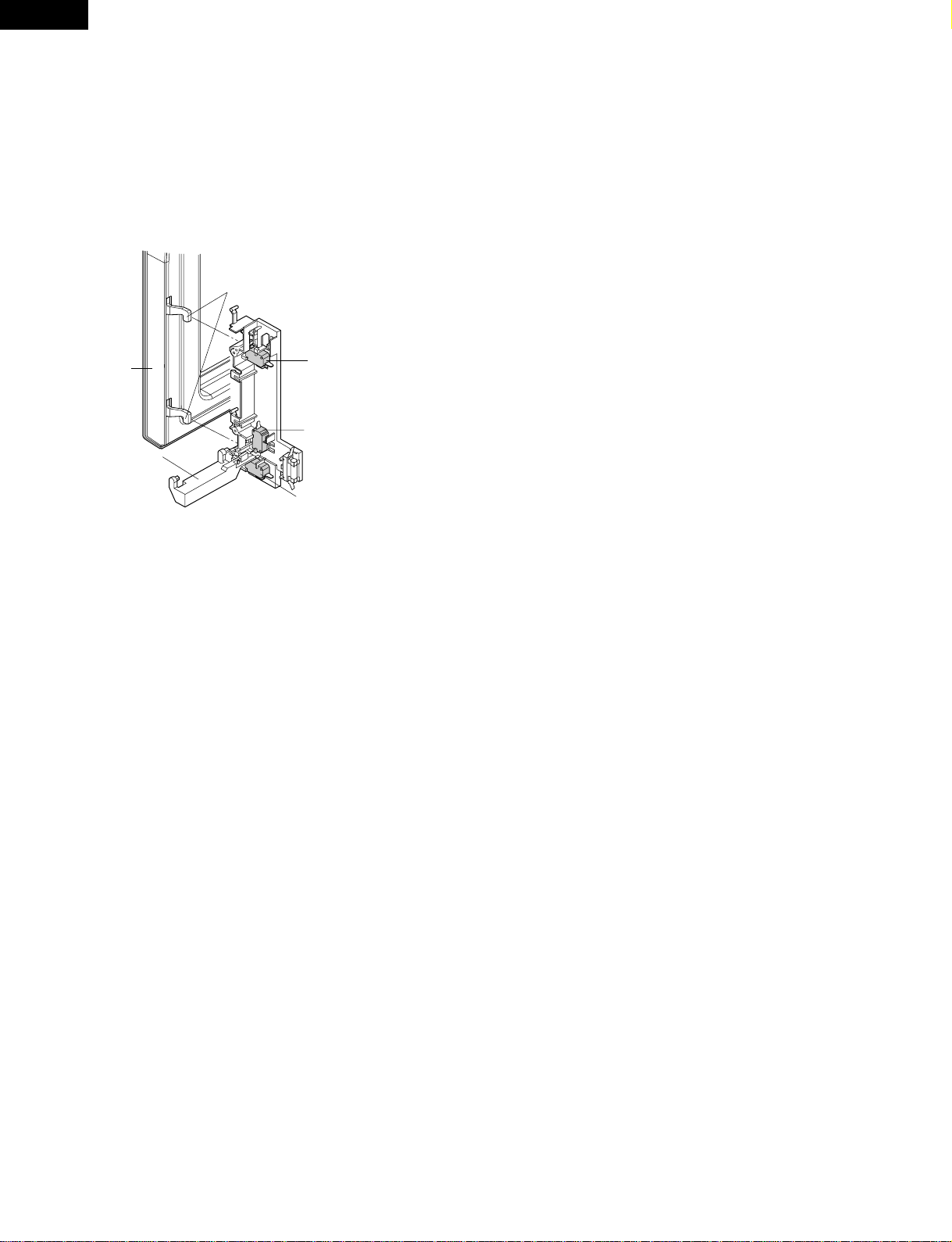
DOOR OPEN MECHANISM
Thedoorisopenedbypushingtheopenbuttononthecontrol
panel, refer to the Figure D-1. When the open button is
pushed, the open button pushes up the switch lever, and
then the switch lever pushes up the latch head. The latch
heads are moved upward and released from latch hook.
Now the door will open.
Figure D-1. Door Open Mechanism
DOOR SENSING AND SECONDARY INTERLOCK
SWITCHES
The secondary interlock switch is mounted in the lower
positionofthelatch hookandthedoorsensingswitchinthe
primaryinterlocksystemismountedintheupperpositionof
thelatchhook.Theyareactivatedbythelatchheadsonthe
door. When the door is opened, the switches interrupt the
power to all high voltage components. A cook cycle cannot
take place until the door is firmly closed thereby activating
both interlock switches. The primary interlock system con-
sists of the door sensing switch and primary interlock relay
located on the control circuit board.
MONITOR SWITCH
Themonitorswitchisactivated(thecontactsopened)bythe
latch head on the door while the door is closed. The switch
is intended to render the oven inoperative, by means of
blowing the monitor fuse, when the contacts of the primary
interlock relay (RY2) and secondary interlock switch fail to
open when the door is opened.
Functions:
1. Whenthedoorisopened,themonitorswitchcontactclose
(totheONcondition)duetotheirbeingnormallyclosed.At
this time the primary interlock relay (RY2) and secondary
interlock switch are in the OFF condition (contacts open)
due to their being normally open contact switches.
2. As the door goes to a closed position, the monitor switch
contactsarefirstopenedandthenthedoorsensingswitch
and the secondary interlock switch contacts close. (On
openingthedoor,eachoftheseswitchesoperateinversely.)
3. If the door is opened, and the primary interlock relay
(RY2) and secondary interlock switch contacts fail to
open,themonitorfuseblowssimultaneouslywithclosing
of the monitor switch contacts.
CAUTION: BEFORE REPLACING A BLOWN MONITOR
FUSE TEST THE DOOR SENSING SWITCH,
PRIMARYINTERLOCKRELAY(RY2),RELAY
(RY1), SECONDARY INTERLOCK SWITCH
AND MONITOR SWITCH FOR PROPER OP-
ERATION.(REFERTOCHAPTER"TESTPRO-
CEDURE").
NOTE: MONITOR FUSE AND MONITOR SWITCH ARE
REPLACED AS AN ASSEMBLY.
TURNTABLE MOTOR
The turntable motor rotates the turntable located on the
bottomofthe oven cavity, so thatthefoodson the turntable
cookevenlyduringcooking.Theturntablemayturnineither
direction.
COOLING FAN MOTOR
Thecoolingfanmotordrivesabladewhichdrawsexternalcool
air.Thiscoolairisdirectedthrough the airvanessurrounding
themagnetronandcoolsthemagnetron.Thisairischannelled
throughtheovencavitytoremovesteamandvaporsgivenoff
from the heating foods. It is then exhausted through the
exhausting air vents at the oven cavity.
MONITOR FUSE
1. Themonitorfuseblowswhenthecontacts(COM-NO)of
theprimaryinterlockrelay(RY2)andsecondaryinterlock
switchremainclosedwiththeoven door openandwhen
the monitor switch closes.
2. If the wire harness or electrical components are short-
circuited, this monitor fuse blows to prevent an electric
shock or fire hazard.
CAVITY TEMPERATURE FUSE
The cavity temperature fuse located on the top of the oven
cavity,isdesignedtopreventdamagetotheovenbyfire.Ifthe
foodloadisovercooked,byeithererrorincooktimeordefect
in the control unit, the cavity temperature fuse will open.
Undernormaloperation,thecavitytemperaturefuseremains
closed. However, when abnormally high temperatures are
reachedwithintheovencavity,thecavitytemperaturefusewill
open at 302OF(150OC) causing the oven to shut down.
NOTE: This is fuse. It does not reset.
Magnetron TEMPERATURE FUSE
Themagnetrontemperaturefuselocatednearthemagnetron
is designed to prevent damage to the magnetron if an over
heatedconditiondevelopsinthetubeduetocoolingfanfailure,
obstructed air guide, dirty or blocked air intake, etc.
Under normal operation, the magnetron temperature fuse
remains closed. However, when abnormally high tempera-
tures are reached within the magnetron, the magnetron tem-
perature fuse will open at 302OF(150OC) causing the oven to
shut down.
NOTE: This is fuse. It does not reset.
Door Sensing
Switch
Monitor Switch
Switch Lever
Secondary Interlock
Switch
Latch Heads
Door

9
R-409EW
R-410EK
R-410EW
TROUBLESHOOTING GUIDE
Never touch any part in the circuit with your hand or an uninsulated tool while the power supply is connected.
Whentroubleshootingthemicrowave oven,itishelpfultofollow theSequenceofOperationinperforming thechecks.Many
ofthepossiblecausesoftroublewillrequirethataspecifictestbeperformed.Thesetestsaregivenaprocedureletterwhich
will be found in the "Test Procedure "section.
IMPORTANT: If the oven becomes inoperative because of a blown monitor fuse, check the monitor switch, relay (RY1)
primary interlock relay (RY2), door sensing switch and secondary interlock switch before replacing the
monitorfuse.Ifthemonitorfuseisreplaced,themonitorswitchmustalsobereplaced.UsepartFFS-BA016/
KIT as an assembly.
IMPORTANT: Whenevertroubleshootingisperformedwiththepowersupplycorddisconnected.Itmayin,somecases,be
necessary to connect the power supply cord after the outer case has been removed, in this event:
1. Disconnect the power supply cord, and then remove outer case.
2. Open the door and block it open.
3. Discharge high voltage capacitor.
4. Disconnect the leads to the primary of the power transformer.
5. Ensurethatthe leadsremainisolatedfromothercomponentsandovenchassisbyusing insulationtape.
6. After that procedure, reconnect the power supply cord.
When the testing is completed
1. Disconnect the power supply cord, and then remove outer case.
2. Open the door and block it open.
3. Discharge high voltage capacitor.
4. Reconnect the leads to the primary of the power transformer.
5. Reinstall the outer case (cabinet).
6. Reconnect the power supply cord after the outer case is installed.
7. Run the oven and check all functions.

10
R-409EW
R-410EK
R-410EW
AMAGNETRON ASSEMBLY TEST
1. Disconnect the power supply cord, and then remove outer case.
2. Open the door and block it open.
3. Discharge high voltage capacitor.
TEST PROCEDURES
PROCEDURE
LETTER COMPONENT TEST
Home fuse or circuit breaker blows
whenpowercordispluggedintowall
receptacle
Monitorfuseblowswhenpowercord
is plugged into wall receptacle.
All letters and indicators do not ap-
pear in display when power cord is
first plugged into wall outlet.
Display does not operate properly
when STOP/CLEAR key is touched.
(Buzzershouldsoundand":"ortime
of day should appear in display.)
Oven lamp does not light when door
is opened.
Oven lamp does not go out when
door is closed.
Oven lamp lights but fan motor and
turntable motor do not operate.
Oven does not go into cook cycle
when START pad is touched
Ovenseemstobeoperatingbutlittle
or no heat is produced in oven load.
(Food incompletely cooked or not
cooked at all at end of cook cycle.)
Oven goes into a cook cycle but
extremely uneven heating is pro-
duced in oven load (food).
Oven does not cook properly when
programmed for Cooking Power P-
50 mode. (Operates properly on
Cooking P-HI (HIGH) mode.)
Oven goes into COMPU DEFROST
but food is not defrosted well.
OFF
CONDITION
PROBLEM
CONDITION
SHORT IN POWER CORD
SHORT OR OPENED WIRING
MAGNETRON
POWER TRANSFORMER
H.V. RECTIFIER ASSEMBLY
HIGH VOLTAGE CAPACITOR
CAVITY TEMPERATURE FUSE
MAGNETRON TEMPERATURE FUSE
PRIMARY INTERLOCK SYSTEM
SECONDARY INTERLOCK SWITCH
MONITOR SWITCH
MONITOR FUSE
OVEN LAMP OR SOCKET
COOLING FAN MOTOR
TURNTABLE MOTOR
TOUCH CONTROL PANEL
WRONG OPERATION
LOW VOLTAGE
DIRTY OVEN CAVITY
KEY UNIT
RELAY (RY1)
COMPU DEFROST
FOIL PATTERN ON PWB.
POSSIBLE CAUSE
AND
DEFECTIVE PARTS
TEST PROCEDURE
RE RE
ABCDEEF FGH
RE RE CK
I
CK CK CK
JKLM
COOKING
CONDITION
CK = Check / RE = Replace

11
R-409EW
R-410EK
R-410EW
BPOWER TRANSFORMER TEST
1. Disconnect the power supply cord, and then remove outer case.
2. Open the door and block it open.
3. Discharge high voltage capacitor.
4. Disconnect the primary input terminals and measure the resistance of the transformer with an
ohmmeter. Check for continuity of the coils with an ohmmeter. On the R x 1 scale, the resistance of
the primary coil should be less than 1 ohm and the resistance of the high voltage coil should be
approximately 90 ohms; the resistance of the filament coil should be less than 1 ohm.
5. Reconnect all leads removed from components during testing.
6. Reinstall the outer case (cabinet).
7. Reconnect the power supply cord after the outer case is installed.
8. Run the oven and check all functions.
(HIGHVOLTAGESAREPRESENTATTHE HIGH VOLTAGETERMINAL,SODONOTATTEMPTTO
MEASURE THE FILAMENT AND HIGH VOLTAGE.)
TEST PROCEDURES
PROCEDURE
LETTER COMPONENT TEST
4. To test for an open filament, isolate the magnetron from the high voltage circuit. A continuity check
across the magnetron filament leads should indicate less than 1 ohm.
5. Totestforashortedmagnetron,connecttheohmmeterleadsbetweenthemagnetronfilamentleads
and chassis ground. This test should indicate an infinite resistance. If there is little or no resistance
the magnetron is grounded and must be replaced.
6. Reconnect all leads removed from components during testing.
7. Reinstall the outer case (cabinet).
8. Reconnect the power supply cord after the outer case is installed.
9. Run the oven and check all functions.
MICROWAVE OUTPUT POWER
Thefollowingtestprocedureshouldbecarriedoutwiththemicrowaveoveninafullyassembledcondition
(outer case fitted).
HIGH VOLTAGES ARE PRESENT DURING THE COOK CYCLE, SO EXTREME CAUTION SHOULD
BE OBSERVED.
Power output of the magnetron can be measured by performing a water temperature rise test. This test
shouldonlybeusedifabovetestsdonotindicateafaultymagnetronandthereisnodefectinthefollowing
componentsorwiring:siliconrectifier,highvoltagecapacitorandpowertransformer.Thistestwillrequire
a 16 ounce (453cc) measuring cup and an accurate mercury thermometer or thermocouple type
temperature tester. For accurate results, the following procedure must be followed carefully:
1. Fillthemeasuringcupwith16oz.(453cc)oftapwaterandmeasurethetemperatureofthewaterwith
athermometerorthermocoupletemperaturetester.Stirthethermometerorthermocouplethroughthe
water until the temperature stabilizes. Record the temperature of the water.
2. Place the cup of water in the oven. Operate oven at POWER 10(HIGH) selecting more than 60
secondscooktime.Allowthewatertoheatfor60seconds,measuringwithastopwatch,secondhand
of a watch or the digital read-out countdown.
3. Remove the cup from the oven and again measure the temperature, making sure to stir the
thermometer or thermocouple through the water until the maximum temperature is recorded.
4. Subtractthecoldwatertemperaturefromthehotwatertemperature.Thenormalresultshouldbe 38
to 78OF(21Oto 42.6OC) rise in temperature. If the water temperatures are accurately measured and
tested for the required time period the test results will indicate if the magnetron tube has low power
output(lowriseinwatertemperature)whichwouldextendcookingtimeorhighpoweroutput(highrise
in water temperature) which would reduce cooking time. Because cooking time can be adjusted to
compensate for power output, the magnetron tube assembly should be replaced only if the water
temperaturerisetestindicatesapoweroutputwellbeyondthenormallimits.Thetestisonlyaccurate
if the power supply line voltage is 120 volts and the oven cavity is clean.

12
R-409EW
R-410EK
R-410EW TEST PROCEDURES
PROCEDURE
LETTER COMPONENT TEST
1. Disconnect the power supply cord, and then remove outer case.
2. Open the door and block it open.
3. Discharge high voltage capacitor.
4. Ifthecapacitorisopen,nohighvoltagewillbeavailabletothemagnetron.Disconnectinputleadsand
check for short or open between the terminals using an ohmmeter.
Checkingwithahighohmscale,ifthehighvoltagecapacitorisnormal,themeterwillindicatecontinuity
for a short time and should indicate an open circuit once the capacitor is charged. If the above is not
thecase, check thecapacitor with an ohmmeterto see ifitis shorted betweeneither of the terminals
and case. If it is shorted, replace the capacitor.
5. Reconnect all leads removed from components during testing.
6. Reinstall the outer case (cabinet).
7. Reconnect the power supply cord after the outer case is installed.
8. Run the oven and check all functions.
DHIGH VOLTAGE CAPACITOR TEST
ECAVITY TEMPERATURE FUSE TEST
1. Disconnect the power supply cord, and then remove outer case.
2. Open the door and block it open.
3. Discharge high voltage capacitor.
4. Acontinuitycheckacrossthecavitytemperaturefuseterminalsshouldindicateaclosedcircuitunless
thetemperatureofthe cavitytemperaturefusereachesapproximately302OF(150OC). Anopen cavity
temperaturefuseindicatesoverheatingoftheoven,exchangethe cavitytemperaturefuseandcheck
inside of oven cavity and for improper setting of cooking time or operation of control unit. Check for
restricted air flow through the vent holes of the oven cavity, especially the cooling fan and air guide.
5. Reconnect all leads removed from components during testing.
6. Reinstall the outer case (cabinet).
7. Reconnect the power supply cord after the outer case is installed.
8. Run the oven and check all functions.
MAGNETRON TEMPERATURE FUSE TEST
1. Disconnect the power supply cord, and then remove outer case.
2. Open the door and block it open.
3. Discharge high voltage capacitor.
4. Acontinuitycheckacross the magnetron temperaturefuseterminalsshould indicate a closedcircuit
unlessthetemperatureofthemagnetrontemperaturefusereachesapproximately302OF(150OC).An
open magnetron temperature fuse indicates overheating of the magnetron. Check for restricted air
flow to the magnetron, especially the cooling fan air guide.
5. Reconnect all leads removed from components during testing.
6. Reinstall the outer case (cabinet).
7. Reconnect the power supply cord after the outer case is installed.
8. Run the oven and check all functions.
CHIGH VOLTAGE RECTIFIER TEST
1. Disconnect the power supply cord, and then remove outer case.
2. Open the door and block it open.
3. Discharge high voltage capacitor.
4. Isolate the rectifier from the circuit. Using the highest ohm scale of the meter, read the resistance
across the terminals and observe, reverse the leads to the rectifier terminals and observe meter
reading. If a short is indicated in both directions, or if an infinite resistance is read in both directions,
the rectifier is probably defective and should be replaced.
5. Reconnect all leads removed from components during testing.
6. Reinstall the outer case (cabinet).
7. Reconnect the power supply cord after the outer case is installed.
8. Run the oven and check all functions.
NOTE:Besure to useanohmmeter that willsupplya forwardbiasvoltageof morethan6.3volts.

13
R-409EW
R-410EK
R-410EW
TEST PROCEDURES
PROCEDURE
LETTER COMPONENT TEST
1. Disconnect the power supply cord, and then remove outer case.
2. Open the door and block it open.
3. Discharge high voltage capacitor.
4. Before performing this test, make sure that the secondary interlock switch and the primary interlock
relayareoperatingproperly,accordingtotheaboveSwitchTestProcedure.Disconnectthewirelead
fromthemonitor switch (COM) terminal.Checkthemonitor switch operation byusingtheohmmeter
asfollows.Whenthedoorisopen,themetershouldindicateaclosedcircuit.Whenthemonitorswitch
actuatoris pushed by ascrewdriver through the lowerlatchhole on the frontplateof the ovencavity
withthedooropened(inthisconditiontheplungerofthemonitorswitchispushedin),themetershould
indicate an open circuit. If improper operation is indicated, the switch may be defective. After testing
the monitor switch, reconnect the wire lead to the monitor switch (COM) terminal and check the
continuity of the monitor circuit.
CAUTION: IF THE TEMPERATURE FUSE INDICATES AN OPEN CIRCUIT AT ROOM TEMPERA-
TURE, REPLACE TEMPERATURE FUSE.
1. Disconnect the power supply cord, and then remove outer case.
2. Open the door and block it open.
3. Discharge high voltage capacitor.
4. Isolatetheswitchandconnecttheohmmetertothecommon(COM.)andnormallyopen(NO)terminal
of the switch. The meter should indicate an open circuit with the door open and a closed circuit with
the door closed. If improper operation is indicated, replace the secondary interlock switch.
5. Reconnect all leads removed from components during testing.
6. Reinstall the outer case (cabinet).
7. Reconnect the power supply cord after the outer case is installed.
8. Run the oven and check all functions.
PRIMARY INTERLOCK SYSTEM TEST
DOOR SENSING SWITCH
1. Disconnect the power supply cord, and then remove outer case.
2. Open the door and block it open.
3. Discharge high voltage capacitor.
4. Isolatetheswitchandconnecttheohmmetertothecommon(COM.)andnormallyopen(NO)terminal
of the switch. The meter should indicate an open circuit with the door open and a closed circuit with
the door closed. If improper operation is indicated, replace the door sensing switch.
5. Reconnect all leads removed from components during testing.
6. Reinstall the outer case (cabinet).
7. Reconnect the power supply cord after the outer case is installed.
8. Run the oven and check all functions.
NOTE: Ifthedoorsensingswitchcontactsfailintheopenpositionandthedoorisclosed,thecoolingfan,
turntable and oven light will be activated by RY1.
PRIMARY INTERLOCK RELAY (RY2)
1. Disconnect the power supply cord, and then remove outer case.
2. Open the door and block it open.
3. Discharge high voltage capacitor.
4. Disconnect two (2) wire leads from the male tab terminals of the Primary Interlock Relay. Check the
stateoftherelaycontactsusingaohmmeter.Therelaycontactsshouldbeopen.Iftherelaycontacts
are closed, replace the circuit board entirely or the relay itself.
5. Reconnect all leads removed from components during testing.
6. Reinstall the outer case (cabinet).
7. Reconnect the power supply cord after the outer case is installed.
8. Run the oven and check all functions.
FSECONDARY INTERLOCK SWITCH TEST
GMONITOR SWITCH TEST

14
R-409EW
R-410EK
R-410EW
HBLOWN MONITOR FUSE TEST
TEST PROCEDURES
PROCEDURE
LETTER COMPONENT TEST
1. Disconnect the power supply cord, and then remove outer case.
2. Open the door and block it open.
3. Discharge high voltage capacitor.
4. If the monitor fuse is blown when the door is opened, check the primary interlock relay, secondary
interlockswitchandmonitorswitchaccordingtothe"TESTPROCEDURE"forthoseswitchesbefore
replacing the blown monitor fuse.
CAUTION: BEFORE REPLACING A BLOWN MONITOR FUSE, TEST THE PRIMARY INTERLOCK
RELAY,SECONDARYINTERLOCKSWITCH,DOORSENSINGSWITCHANDMONITOR
SWITCH FOR PROPER OPERATION.
If the monitor fuse is blown by improper switch operation, the monitor fuse and monitor switch must
bereplacedwith"monitorfuseandmonitorswitchassembly"partnumberFFS-BA016/KIT,evenifthe
monitor switch operates normally. The monitor fuse and monitor switch assembly is comprised of a
20 ampere fuse and switch.
5. Reconnect all leads removed from components during testing.
6. Reinstall the outer case (cabinet).
7. Reconnect the power supply cord after the outer case is installed.
8. Run the oven and check all functions.
The touch control panel consists of circuits including semiconductors such as LSI, ICs, etc. Therefore,
unlike conventional microwave ovens, proper maintenance cannot be performed with only a voltmeter
andohmmeter.Inthisservicemanual,thetouchcontrolpanelassemblyisdividedintotwounits,Control
Unit and Key Unit, and also the Control Unit is divided into two units, LSI Unit and Power Unit, and
troubleshooting by unit replacement is described according to the symptoms indicated.
Before testing,
1) Disconnect the power supply cord, and then remove outer case.
2) Open the door and block it open.
3) Discharge high voltage capacitor.
4) Disconnect the leads to the primary of the power transformer.
5) Ensure that these leads remain isolated from other components and oven chassis by using insulation tape.
6) After that procedure, re-connect the power supply cord.
1. Key Unit.
NOTE :
1) Disconnect the power supply cord, and then remove outer case.
2) Open the door and block it open.
3) Discharge high voltage capacitor.
4) Check Key unit ribbon connection before replacement.
5) Reconnect all leads removed from components during testing.
6) Re-install the outer case (cabinet).
7) Reconnect the power supply cord after the outer case is installed.
8) Run the oven and check all functions.
ITOUCH CONTROL PANEL ASSEMBLY TEST
5. Reconnect all leads removed from components during testing.
6. Reinstall the outer case (cabinet).
7. Reconnect the power supply cord after the outer case is installed.
8. Run the oven and check all
functions.
Monitor
Switch
Secondary Interlock Switch
Screw Driver
Ohmmeter
RED WHT/WHT

15
R-409EW
R-410EK
R-410EW
The following symptoms indicate a defective key unit.
a) When touching the pads, a certain pad produces no signal at all.
b) When touching a number pad, two figures or more are displayed.
c) When touching the pads, sometimes a pad produces no signal.
If the Key unit is defective.
1) Disconnect the power supply cord, and then remove outer case.
2) Open the door and block it open.
3) Discharge high voltage capacitor.
4) Replace the Key unit.
5) Reconnect all leads removed from components during testing.
6) Re-install the outer case (cabinet).
7) Reconnect the power supply cord after the outer case is installed.
8) Run the oven and check all functions.
2. Control Unit
Thefollowingsymptomsindicateadefectivecontrolunit.Beforereplacingthecontrolunit,performthe
Key unit test (Procedure J) to determine if control unit is faulty.
2-1 In connection with pads.
a) When touching the pads, a certain group of pads do not produce a signal.
b) When touching the pads, no pads produce a signal.
2-2 In connection with indicators
a) At a certain digit, all or some segments do not light up.
b) At a certain digit, brightness is low.
c) Only one indicator does not light.
d) The corresponding segments of all digits do not light up; or they continue to light up.
e) Wrong figure appears.
f) A certain group of indicators do not light up.
g) The figure of all digits flicker.
2-3 Other possible problems caused by defective control unit.
a) Buzzer does not sound or continues to sound.
b) Clock does not operate properly.
c) Cooking is not possible.
When testing is completed,
1) Disconnect the power supply cord, and then remove outer case.
2) Open the door and block it open.
3) Discharge high voltage capacitor.
4) Reconnect all leads removed from components during testing.
5) Re-install the outer case (cabinet).
6) Reconnect the power supply cord after the outer case is installed.
7) Run the oven and check all functions..
TEST PROCEDURES
PROCEDURE
LETTER COMPONENT TEST
JKEY UNIT TEST
1. Disconnect the power supply cord, and then remove outer case.
2. Open the door and block it open.
3. Discharge high voltage capacitor.
4. If the display fails to clear when the STOP/CLEAR pad is depressed, first verify the flat ribbon cable
ismakinggoodcontact,verifythatthedoorsensingswitch(stopswitch)operatesproperly;thatisthe
contactsareclosedwhenthedoorisclosedandopenwhenthedoorisopen.Ifthedoorsensingswitch
(stopswitch)isgood,disconnecttheflatribboncablethatconnectsthekeyunittothecontrolunitand
make sure the door sensing switch is closed (either close the door or short the door sensing switch
connecter).UsetheKeyunitmatrixindicatedonthecontrolpanelschematicandplaceajumperwire
betweenthepinsthatcorrespondtotheSTOP/CLEARpadmakingmomentarycontact.Ifthecontrol
unitrespondsbyclearingwithabeepthekeyunitisfaultyandmustbereplaced.Ifthecontrolunitdoes
not respond, it is faulty and must be replaced. If a specific pad does not respond, the above method
may be used (after clearing the control unit) to determine if the control unit or key pad is at fault.
5. Reconnect all leads removed from components during testing.

16
R-409EW
R-410EK
R-410EW
WARNING:Theovenshouldbefullyassembledbeforefollowingprocedure.
(1) Place one cup of water in the center of the turntable tray in the oven cavity.
(2)Close the door, touch the " steaks / chops " pad once.
(3)The oven is in Compu Defrost cooking condition.
(4)The oven will operate as follows
1ST STAGE 2ND STAGE
WEIGHT LEVEL TIME LEVEL TIME
0.5lb 60% 45sec. 40% 20sec.
6. Re-install the outer case (cabinet).
7. Reconnect the power supply cord after the outer case is installed.
8. Run the oven and check all functions.
TEST PROCEDURES
PROCEDURE
LETTER COMPONENT TEST
1. Disconnect the power supply cord, and then remove outer case.
2. Open the door and block it open.
3. Discharge high voltage capacitor.
4. Disconnect the leads to the primary of the power transformer.
5. Ensurethattheseleadsremainisolatedfromothercomponentsandovenchassisbyusinginsulation
tape.
6. After that procedure, re-connect the power supply cord.
7. Remove the outer case and check voltage between Pin No. 1 of the 2 pin connector (A) and the
common terminal of the relay RY1 on the control unit with an A.C. voltmeter.
The meter should indicate 120 volts, if not check oven circuit.
RY1 and RY2 Relay Test
These relays are operated by D.C. voltage
Check voltage at the relay coil with a D.C. voltmeter during the microwave cooking operation.
DC. voltage indicated ............. Defective relay.
DC. voltage not indicated ........ Check diode which is connected to the relay coil. If diode is good,
control unit is defective.
RELAY SYMBOL OPERATIONAL VOLTAGE CONNECTED COMPONENTS
RY1 Approx. 11.8V D.C. Oven lamp / Turntable motor / Cooling fan motor
RY2 Approx. 10.7V D.C. Power transformer
8. Disconnect the power supply cord, and then remove outer case.
9. Open the door and block it open.
10. Discharge high voltage capacitor.
11. Reconnect all leads removed from components during testing.
12. Re-install the outer case (cabinet).
13. Reconnect the power supply cord after the outer case is installed.
14. Run the oven and check all functions.
LCOMPU DEFROST TEST
Key Unit
KRELAY TEST
54321
09876
START
BEVERAGE
POPCORN
POWER
LEVEL CASSE-
ROLE
MINUTE
PLUS
DINNER
PLATE
COMPU
DEFROST
ROLLS &
MUFFINS
GROUND
MEAT
FROZEN
ENTREES
BAKED
POTATOES
STOP
CLEAR
TIMER
CLOCK
FRESH
VEGETABLES
FROZEN
VEGETABLES
G 8
G 9
G10
G11
G12
G13
G14
G 7 G 6 G 5 G 4 G 3 G 2 G 1
MICROWAVE
PIZZA
R-409EW R-410EK/EW
54321
09876
START
KEEP WARM
POPCORN
POWER
LEVEL RICE
MINUTE
PLUS
STEAKS
CHOPS
<COMPU
DEFROST>
GROUND
MEAT
REHEAT
CENTER
CHICKEN
PIECES
GROUND
MEAT
FROZEN
ENTREES
BAKED
POTATOES
STOP
CLEAR
TIMER
CLOCK
FRESH
VEGETABLES
FROZEN
VEGETABLES
G 8
G 9
G10
G11
G12
G13
G14
G 7 G 6 G 5 G 4 G 3 G 2 G 1

17
R-409EW
R-410EK
R-410EW
(5) If improper operation is indicated, the control unit is probably defective and should be checked.
TEST PROCEDURES
PROCEDURE
LETTER COMPONENT TEST
Toprotecttheelectroniccircuits,thismodelisprovidedwithafinefoilpatternaddedtotheprimaryonthe
PWB, this foil pattern acts as a fuse.
1. Foil pattern check and repairs.
1) Disconnect the power supply cord, and then remove outer case.
2) Open the door and block it open.
3) Discharge high voltage capacitor.
4) Follow the troubleshooting guide given below for repair.
STEPS OCCURRENCE CAUSE OR CORRECTION
1 Only pattern at "a" is broken. *Insert jumper wire J1 and solder.
2 Pattern at "a" and "b" are broken. *Insert the coil RCILF2003YAZZ between "c" and "d".
5) Makeavisualinspectionof thevaristor.
Checkforburneddamageandexamine
the transformer with a tester for the
presence of layer short-circuit (check
the primary coil resistance which is
approximately540ohms ±20%).Ifany
abnormalconditionisdetected,replace
the defective parts.
6) Reconnect all leads removed from components during testing.
7) Re-install the outer case (cabinet).
8) Reconnect the power supply cord after the outer case is installed.
9) Run the oven and check all functions.
2.Followthetroubleshootingguidegivenbelow,ifindicatordoesnotlightupafterabovecheckandrepairs
are finished.
1) Disconnect the power supply cord, and then remove outer case.
2) Open the door and block it open.
3) Discharge high voltage capacitor.
4) Disconnect the leads to the primary of the power transformer.
5) Ensure that these leads remain isolated from other components and oven chassis by using
insulationtape.
6) After that procedure, re-connect the power supply cord.
7) Follow the troubleshooting guide given below for repair.
STEPS OCCURRENCE CAUSE OR CORRECTION
The rated AC voltage is not present between
1 Pin No. 1 of the 2-pin connector (A) and the Check supply voltage and oven power cord.
common terminal of the relay RY1.
2The rated AC voltage is present at primary Low voltage transformer or secondary circuit defective.
side of low voltage transformer. Check and repair.
8) Disconnect the power supply cord, and then remove outer case.
9) Open the door and block it open.
10) Discharge high voltage capacitor.
11) Reconnect all leads removed from components during testing.
12) Re-install the outer case (cabinet).
13) Reconnect the power supply cord after the outer case is installed.
14) Run the oven and check all functions.
MFOILPATTERNONTHEPRINTED WIRING BOARD TEST

18
R-409EW
R-410EK
R-410EW
TOUCH CONTROL PANEL ASSEMBLY
OUTLINE OF TOUCH CONTROL PANEL
The touch control section consists of the following units.
(1) Key Unit
(2)ControlUnit(TheControlUnitconsistsofPowerUnitand
LSI Unit).
The principal functions of these units and the signals com-
municated among them are explained below.
Key Unit
The key unit is composed of a matrix, signals generated in
theLSIaresenttothekeyunitthroughP20,P21,P22,P23,
P24, P25, P26 and P27.
When a key pad is touched, a signal is completed through
the key unit and passed back to the LSI through P41, P43,
P44, P45 and AN0 to perform the function that was re-
quested.
Control Unit
Control unit consists of LSI, ACL circuit, indicator circuit,
power source circuit, relay circuit, buzzer circuit, synchro-
nizing signal circuit and back light circuit.
1) ACL
ThiscircuitgeneratesasignalwhichresetstheLSItothe
initial state when power is supplied.
2) Indicator Circuit
This circuit consists of 22 segments and 3 common
electrodes using a Liquid Crystal Display.
3) Power Source Circuit
This circuit generates voltages necessary in the control
unit from the AC line voltage.
Inaddition,thesynchronizingsignalisavailableinorder
to compose a basic standard time in the clock circuit.
Symbol Voltage Application
VC -5V LSI(IC1)
4) Relay Circuit
A circuit to drive the magnetron, fan motor, turntable
motor and light the oven lamp.
5) Buzzer Circuit
The buzzer is responsive to signals from the LSI to emit
audiblesounds(keytouchsoundandcompletionsound).
6) Synchronizing Signal Circuit
The power source synchronizing signal is available in
order to compose a basic standard time in the clock
circuit.
It accompanies a very small error because it works on
commercial frequency.
7) Door Sensing Switch
A switch to “tell” the LSI if the door is open or closed.
8) Back Light Circuit
Acircuittodrivethebacklight(LightemittingdiodesLD1-
LD4).
Pin No. Signal I/O Description
LSI(IXA096DR)
The I/O signal of the LSI(IXA096DR) is detailed in the following table.
1-2 VL2-VL1 IN Powersourcevoltageinput terminal.
StandardvoltageforLCD.
3-6 AN7-AN4 IN Terminal to change cooking input according to the Model.
ByusingtheA/DconvertercontainedintheLSI,DCvoltageinaccordancewiththeModel
in operation is applied to set up its cooking constant.
7 P63 OUT Terminalnotused.
8 AN2 IN Input terminal to judge the model.
The one of signals P20 - P27 will be input into AN2 through one of G1 - G8 lines on key
matrix. The LSI will judge the model by this signal.
9 AN1 IN To input signal which communicates the door open/close information to LSI.
Door close "H" level signal (0V). Door open "L" level signal (-5V).
10 AN0 IN Input terminal to judge the model.
ConnectedtoGNDthroughthepull-downresistorR79.
This manual suits for next models
2
Table of contents
Other Sharp Microwave Oven manuals

Sharp
Sharp Carousel R-350L User manual

Sharp
Sharp Carousel R-380E User manual

Sharp
Sharp R-230F User manual

Sharp
Sharp Carousel R-1510 User manual

Sharp
Sharp R-410HK User manual

Sharp
Sharp R-677W User manual

Sharp
Sharp R-209FW User manual

Sharp
Sharp R-297F User manual

Sharp
Sharp R-393M Instruction Manual

Sharp
Sharp Carousel R-216L User manual

Sharp
Sharp R-9H55 User manual

Sharp
Sharp R-211A User manual

Sharp
Sharp R-320DK User manual

Sharp
Sharp R-383M Instruction Manual

Sharp
Sharp YC-GS02E User manual

Sharp
Sharp R-6280 User manual

Sharp
Sharp R-420D User manual

Sharp
Sharp R-772M User manual

Sharp
Sharp R-757M Instruction Manual

Sharp
Sharp R-667R User manual