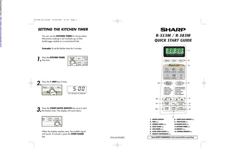
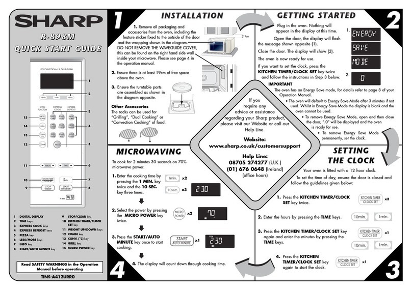
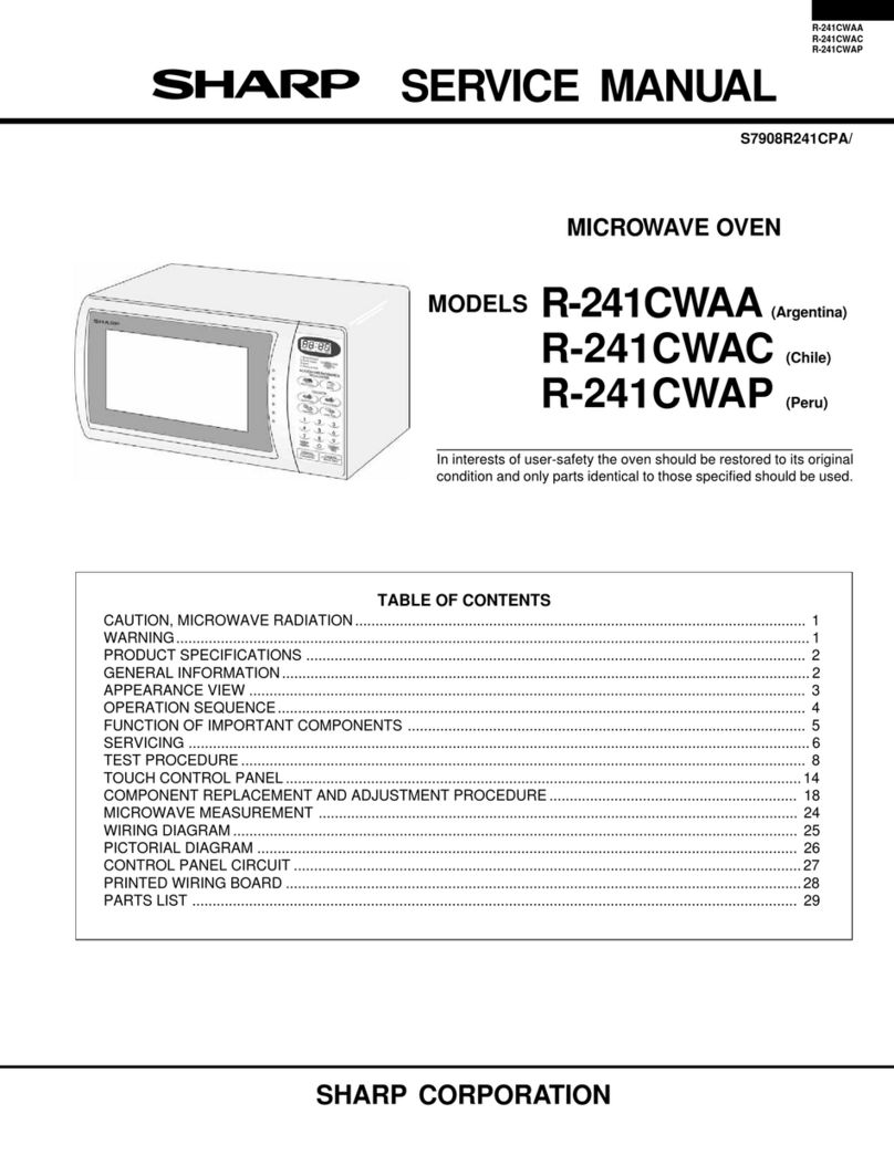
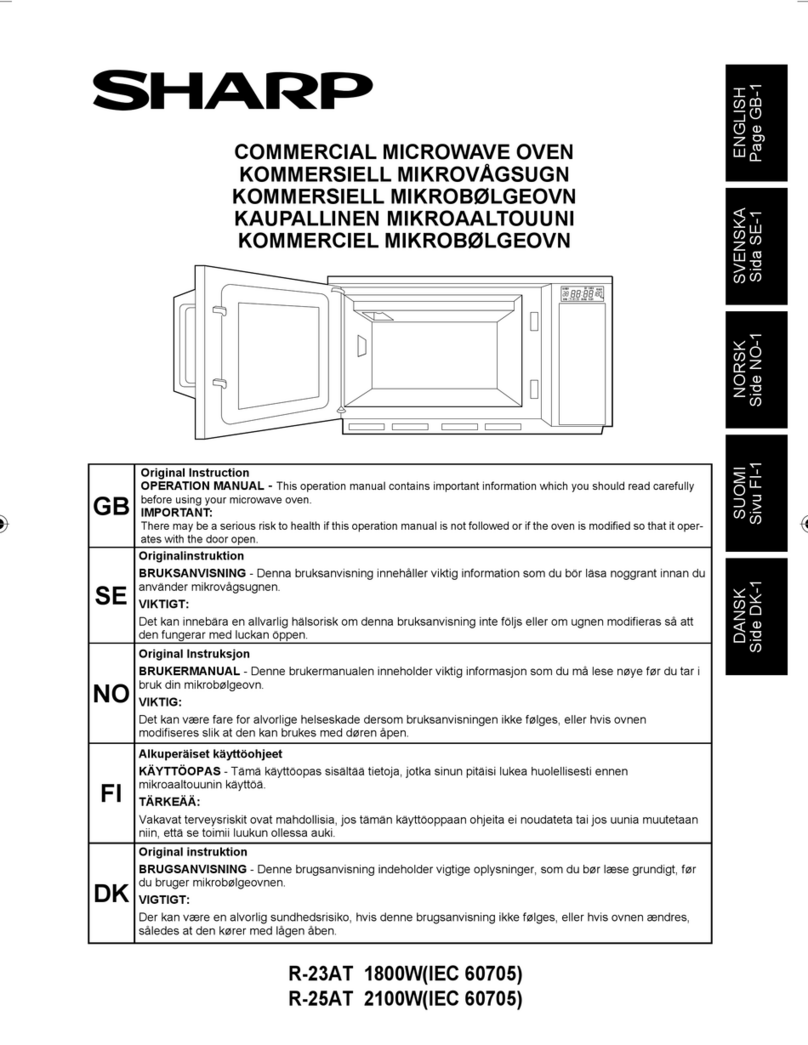
manuals.online logo
Brands
  1. Home
  2. •
  3. Brands
  4. •
  5. Sharp
  6. •
  7. Microwave Oven
  8. •
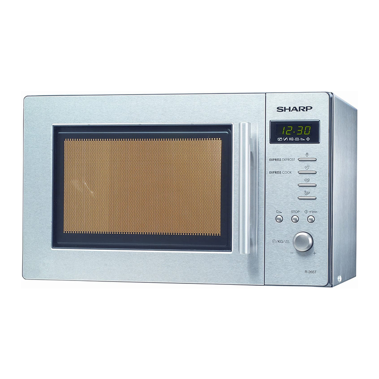
  9. Sharp R-4A54 User manual

Sharp R-4A54 User manual

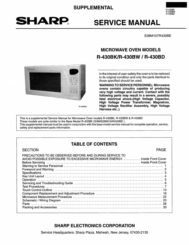
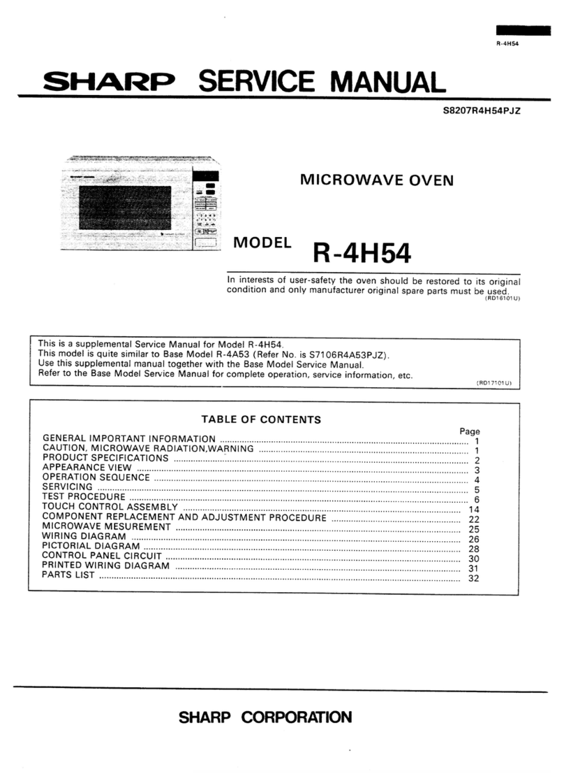
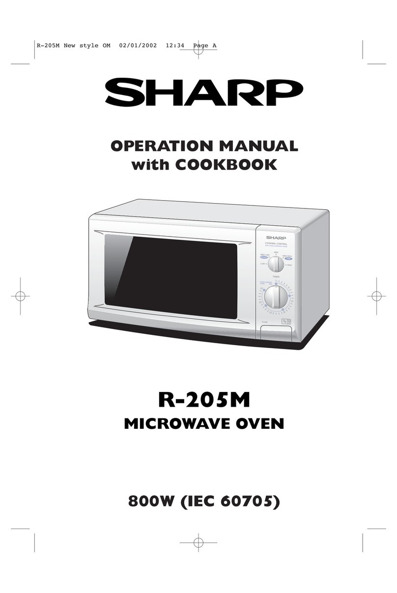
SHARF’ SERVICE MANUAL
S8206R4A54PJZ
MICROWAVE OVEN
Photo R-4A54 R-4A54B
In interests of user-safety the oven should be restored to its original
condition and only manufacturer original spare parts must be used.
(RD16701U)
This is a supplemental Service Manual for Modei R-4A54 etc.
Those models are quite similar to Base Model R-4A53 (Refer No. is S7106R3A53PJZ).
Use this supplemental manual together with the Base Model Service Manual.
Refer to the Base Model Service Manual for complete operation, service information, etc. CRD17101lJ1
TABLE OF CONTENTS
GENERAL IMPORTANT INFORMATION Page
...................................................................................................... 1
CAUTION, MICROWAVE RADlATlON,WARNING ...................................................................................... 1
PRODUCT SPECIFICATIONS ......................................................................................................................... 2
APPEARANCE VIEW ........................................................................................................................................ 3
SERVICING ........................................................................................................................................................ 4
TEST PROCEDURE ........................................................................................................................................... 5
TOUCH CONTROL ASSEMBLY
COMPONENT ..................................................................................................................... 8
REPLACEMENT AND ADJUSTMENT PROCEDURE .....................................................
WIRING DIAGRAM 13
.......................................................................................................................................
PICTORIAL DIAGRAM 15
..................................................................................................................................
CONTROL PANEL CIRCUIT 17
.........................................................................................................................
PRINTED WIRING DIAGRAM 19
PARTS LIST ..................................................................................................................... 20
.................................................................................................................................................... 21
SHARP CORPORATION
R -4A54
R-4A54B
R -4A54
R -4A54B
SERVICE MANUAL
SHARP
MICROWAVE OVEN
R-4A54/ R-4A54B
GENERAL IMPORTANT INFORMATION
This Manual has been prepared to provide Sharp Corp. Service
engineers with Operation and Service Information.
It is recommended that service engineers carefully study the
entire text of this manual and base model manual, so they will
be qualified to render satisfactory customer service.
fRD36106U)
CAUTION
MICROWAVE RADIATION
-
Service engineers should not be exposed to the micro-
wave energy which may radiate from the magnetron or
other microwave generating devices if it is improperly
used or connected. All input and output microwave
connections, waveguides, fianges and gaskets must be
secured. Never operate the device without a microwave
energy absorbing load attached. Never look into an
open waveguide or antenna while the device is ener-
gized. -
(RD36203U)
WARNING I
Never operate the oven until the following points are
ensured.
(A)The door is tightly closed.
(B) The door brackets and hinges are not defective. I
(C)The door packing is not damaged.
(D)The door is not deformed or warped.
(E) There is not any other visible damage with the oven. I
Servicing and repair work must be carried out only by ’
trained service engineers.
All the parts marked “*‘I
more than 250V. on parts list are used at voltages
(RD51110u)
SHARP CORPORATION
OSAKA, JAPAN
\\ t ‘.a~ *\T ” ..*mh
“*a* .” ‘-*e ~~~~~~~“~~~~~~~~~~ ; tp :, s % \
.\\ \ c
e&>a$*:. : . ,>$b!\ ;” I. >, ‘%,vltyeg_, ,- “X, “” I #.+>l ,:&~L~^‘~,iig,,
~Wd&tahXwk$%$:*~-~,“*> $- mi y‘;‘ ‘*4+, k”-” I $
*“:*.” i 9 ‘,*“- +
; a.22:=: : I” “““AZ *‘,gz 2. +$&g
* 1
a,_ * $4“-3% a.b&lv&-,,?$q ,q’*y
a”
:> &a \Q 2:
x p * :r j
p*sT A* I_* b- *7&2~r *?a aad L >“, &< 1 /LI b **> __ _c
-;c a+,?,~~~~a <q ,,,‘- b. ,:,y %x$< (‘.
“h-d $: i
-SW$.Pi% I *. %,
\ - a?<>-;$p a.+*
,.L
-b&--.:&& ,<<-b&--.:& & ,<<
%gd&:k*%gd&:k*
**y-y- .“i:
.“i: PRODUCT SPECIFICATIONS
PRODUCT SPECIFICATIONS .%
A”‘$,”
..%
A”‘$,”
.
*avow*avow
^ c a*, + **s, @,< ” I ,“.;-
‘ +-
--.**$a- 1--.**$a- 1
@A *y&-a@A*y&-a
’ SERVICING 4
>W,r%=y>W,r%=y
’ SERVICING 4
-w”,*”-w”,*”
t&&e*w‘a*t&&e*w‘a* ~ 5~ 5
*; i :s* *_^c.,->*b*>*; i :s* *_^c.,->*b*> I*I*
\\ ‘9‘9 )‘\ +)‘\ + ‘ j.”‘ j.”
* Qb\\c ,‘a,* Qb\\c ,‘a, rr EdP,,1EdP,,1
-‘rr-“,-‘rr-“, i es“-e+-I.ii es“-e+-I.i
I \__-dhI \__-dh‘-&\‘C’,‘,\‘-&\‘C’,‘,\ I 1*&I 1*& “’“,“’“,
jj
‘G%+<“)s&\‘G%+<“)s&\ _‘* _.’_‘* _.’
;e*fi * “,“,
“*3b“*3btt ‘2:”‘2:”
j
j
v*L~*‘rl.Y‘*v*L~*‘rl.Y‘* TOUCH CONTROL PANEL
TOUCH CONTROL PANEL
:”$$$&“J&:”$$$&“J&‘3‘3
%<- j. ASSEMBLY
2 ; ASSEMBLY ff
~‘*Jd
:s:*_&q%; - I> .
n-e*”,“”9,I*y&q++&:”‘y\”-^cF ” i *
\ A$
I~\t ,A: .b_‘ \ \j‘ .
” ‘. :.&”I^’*.vp*
.*-a
*->_ v”,,&+*t;.z* I
bL,\.&,-*-s * I^ 1 ^,“& ,a;:,
*< 1
,x2-+h,? * *.“.<A/
**‘?k+ : COMPONENT REPLACEMENT
k “, ‘,
-< ~‘*J d
:s: *_&q%; - I> .
n-e*”,“”9,I * y&q++&:” ‘y\”- ^cF ” *
\ A$
I ~\t i
,A : .b _‘ \ \j ‘ .
” ‘. :.&” I ^’* .vp*
.*-a*->_ v”,, &+ *t;.z * I
b L,\.&,-*-s * I^ 1 ^,“& ,a;:,
*< 1
,x2 -+h,? * *.“.<A/
**‘?k+ : COMPONENT REPLACEMENT
k “, ‘,
”f r-:\
_ n-et\ AND ADJUSTMENT PROCEDURE : q2
. *
\ << f L
” rT.*”“, *_
b , i
~ ‘” ,
WIRING DIAGRAM
* <_ j. \>” . * 0s _
1 h \ b*
j
* .‘- -hp,y
_* a - PARTS L,ST
(RD37201 U)
R -4A54
R -4A548
PRODUCT SPECIFICATIONS
SPECIFICATION
ITEM
Power Requirements
Power Consumption
Power Output
Outside Dimensions
Cooking Cavity Dimensions
Turntable diameter
Control Complement
I DESCRIPTION
/ 240 Volts(Australia)/230-240 Volts(New Zealand)
/ 50 Hertz
I Single phase, 3 wire earthed
/ 1400w
1 750 watts nominal of RF microwave energy (AS 2895 1986)
’ 9OOW watts nominal of RF microwave energy (IEC-705-I 988)
Operating frequency of 2450M Hz
1 Width 550mm
Height 312mm
/ Depth 420mm
/ Width 381 mm
1 Height 211 mm
1 Depth 41 I mm
/ 360mm
I
j Touch Control System
i Ciock( I:00 - 12:59 )
1 Timer (0 - 99 minutes 99 seconds )
i Microwave Power for Variable Cooking
Set Weight
/ Repetition Rate;
HIGH ................................. Full power throughout the cooking time
MEDIUM HIGH ....................................... approx. 70% of Full Power
I MEDIUM .................................................. approx. 50% of Full Power
I MEDIUM LOW ...*.................................... approx. 30% of Full Power
! LOW .......................................................... approx. 10% of Full Power
1 INSTANT ACTION
j SERVE QUANTITY pads
/ NUMBER pads
I EASY DEFROST
i AUTO START /CLOCK
INSTANT COOK/START
/ STOP CLEAR
j POWER LEVEL
j AUTO COOK
j MEMORY
! Approx. 17.0 kg
NOTE: Numbers and letters shown after sentences such as “RD44101 U” are for factory use only.
2
R -4A54
R-4A540
APPEARANCE VIEW
1. Ventilation openings
2. Oven lamp
3. Hinges
4. Safety door latches
5. See through door
6. Coupling
7. Door open button
TOUCH CONTROL PANEL
.-a--- _.- _ --.-_. _ _ _- /‘wrA ,VT A&riO,Y
8. Touch Control Panel
9. Digital readout
10. Waveguide cover
11. Access cover for oven lamp replacement
12. Power supply cord
INSJANJ ACllUN PADS
Press once to cook or reheat 8
popular menu. Frozen Dinner
AUTO
Press to select Auto Cook
mode.
AUTO COOK MENUS-
NUMBER PADS
Press to enter cooking times,
clock time, weight or quantity
of food, or to select the Auto
Cook menus.
POWER LEVEL PAD
Press to select microwave
power setting.
If not pressed, HIGH is auto-
matically selected.
STOP/CLEAR PAD
Press to erase during pro-
gramming.
Press once to stop operation
of oven during cooking; press
twice to cancel cooking pro-
gramme.
1 serve 11
G-?
Bacon
1 serve ~
-
I
Rice 8 Pasta
‘12cup
RehealBevecage/Soup
1 cup
Chicken Pieces
1 serve
Casseroles
1 serve .
I
d
1 Fresh vegetables
2 Frozen vegetabtes
3 Jackel poloto
4 Roasl lamb
5 Seasoned roast
-2 SERVE Q(uARTIT-Y PAD
To cook two serves, press this
pad prior to pressing the IN-
STANT ACTION pad.
-3 SERVE QUANTITY PAD
Tocookthreeserves. press this
pad prior to pressing the IN-
STANT ACTION pad.
-4 SERVE QUANTITY PAD
To cook four serves, press this
pad prior to pressing the IN-
STANT ACTION pad.
-EASY DEFROST PAD
Press to defrost meat by en-
tering weight.
*MORE (A). LESS (v’) PADS
Press to increase/decrease the
time in one minute increments
during cooking or to alter the
doneness for the Auto Cook,
Instant Action or Easy Defrost
modes.
,INSTANT COOK/START PAD
Press once to cook for 1 minute
at HIGH or increase by 1 minute
multiples each time $his pad is
pressed during cooking.
Press to start oven after setting
programmes.
3
R-4A!i4
R-4AMB
SERVICING
WARNING TO SERVICE PERSONNEL
Microwave ovens contain circuitry capable of producing very high voltage and current, contact with any part
of the high voltage circuit will result in electrocuition.
REMEMBER TO CHECK 3D
:
3
Disconnect the supply.
Door opened, and wedged open.
Discharge high voltage capacitor.
WARNING AGAINST THE CHARGE OF THE
HIGH-VOLTAGE CAPACITOR
The high-voltage capacitor remains charged
about 60 seconds after the oven has been
switched off. Wait for 60 seconds and then
short-circuit the connection of the
high-voltage capacitor (that is, of the con-
necting lead of the high-voltage rectifier)
against the chassis with the use of an insu-
lated screwdriver.
Sharp recommend that wherever possible
fault-finding is carried out with the supply discon-
nected. It may in, some cases, be necessary to
connect the supply after the outer case has been
removed, in this event carry out 3D checks and then
disconnect the leads to the primary of the power
transformer. Ensure that these leads remain isolated
from other components and the oven chassis. (Use
insulation tape if necessary.) When the testing is
completed carry out 3D checks and reconnect the
leads to the primary of the power transformer.
REMEMBER TO CHECK 4R
1) Reconnect all leads removed from components
during testing.
2) Replace the outer case (cabinet).
3) Reconnect the supply.
4) Run the oven. Check all functions.
Microwave ovens should not be run empty. To test
for the presence of microwave energy within a
cavity, place a cup of cold water on the oven
turntable, close the door and set the microwave
timer for two (2) minutes. Set the power level to
HIGH and push the START button. When the two
minutes has elapsed (timer at zero) carefully check
that the water is now hot. If the water remains cold
carry out 3D checks and re-examine the con-
nections to the component being tested.
When all service work is completed, and the oven is fully assembled, the microwave power output should
be checked and a microwave leakage test carried out.
(RD81001 H)
4
R -4A54
R-4A54B
TEST PROCEDURES
PROCEDURE
LETTER COMPONENT TEST
MICROWAVE OUTPUT POWER (2 LITRE WATER LOAD)
The following test procedure should be carried out with the microwave oven in a fully assembled
condition (with ou?er case fitted). Microwave output power from the magnetron can be measured
by way of substitution, i.e. it can be measured by using a water load how much it can be absorbed
by the water load. To measure the microwave output power in the microwave oven, the relation
of calorie and watt is used. On the other hand, if the temperature cf the water with V(ml) rises
AT (“C) during this microwave heating period, the calorie of the water is V x AT.
The formula is as follows;
P= 8330 x AT
t
Our condition for the water load is as follows:
Room temperature ............................
23 +2”C
Water load ......2000 ml Initial temperature Power supply Voltage .............Rated voltage
.......23+ 1“C Heating time ...... 1min. 51 sec.
P = 75 x AT
Measuring method:
A) Use two 1 litre Pyrex beakers with a diameter of approximately of 12cms.
B) Place 1 litre of 23°C water in each beaker.
C) Mark Tl on the one beaker and mark T2 on the other one. And stir the water and measure the
temperature of water the thermometer and note them. The graduation of the thermometer must
be scaled by 0.1 “C at minimum and an accurate mercury thermometer is recommended.
D) Place the two beakers as touching each other in the centre of the cavity.
E) Set the timer to I minute and 51 seconds at 100% power (the time required to raise the water
temperature 10 degrees C.)
F) The time must be measured with stopwatch or wristwatch.
G) After 1minute and 51 seconds stop the oven by opening the door.
H) Remove the two beakers from the oven and measure the temperature of the water by stirring
the water with the thermometer and noting the readings.
Example
/ Initial temperature -............................................................................... Tl = 23°C T2 =
Temperature after 1min. 51 set 24°C
. ...................................................I.... Tl = 33°C T2 = 34°C
I Temperature difference Cold-Warm ...............................*...........
Mean temperature rise AT AT1 = 10°C AT2 = 10°C
!
I ........
Measured output power AT = (AT1 +AT2) /‘2 = (103C + 10°C) / 2 = 10°C
I
/ The equation is “P= 75 x AT” ................................................... P= 75 x 10°C = 750 Watts
NOTE: The measured output power should be at least +I5 % of the rated output
power.
CAUTION: 1°C CORRESPONDS TO 75 WATTS.
REPEAT MEASUREMENT IF THE POWER IS INSUFFICIENT.
(Tl OC) (T2 OC) (T2 OCI
Heat up for 1min. 51 sec.
MICROWAVE OUTPUT POWER (1 LITRE WATER LOAD) (RD82AOZJ)
The following test procedure should be carried out with the mi&owave oven in a fully assembled
condition (outer case fitted). Microwave output power from the magnetron can be measured by
way of IEC 705, i.e. it can be measured by using water load how much it can be absorbed by the
water load. To measure the microwave output power in the microwave oven, the relation of cal-
5
R -4A54
R-4A54B
TEST PROCEDURES (CONT’D)
PROCEDURE
LETTER COMPONENT TEST
orie and watt is used. When P(W) heating works for t(second), approximately P x t/4.1 87 calorie
is generated. On the other hand, if the temperature of the water with V(ml) rises AT (“C) during
this microwave heating period, the calorie of the water is V x AT.
The formula is as follows;
Pxt/4.187=VxAT P(W)=4.187xVxAT/t
Our condition for the water load is as follows:
Room temperature .....................around 20°C Power supply Voltage .............Rated voltage
Water load *.......1000 g Initial temperature .......1Of2”C Heating time ................ 47 sec.
P = 90 x AT
Measuring condition:
1. Container
The water container must be a cylindrical borosilicate glass vessel having a maximum material
thickness of 3 mm and an outside diameter of approximately 190 mm.
2. Temperature of the oven and vessel
The oven and the empty vessel are at ambient temperature prior to the start of the test.
3. Temperature of the water
The initial temperature of the water is (10 f 2)“C.
4. Select the initial and final water temperature so that the maximum difference between the final
water temperature and the ambient temperature is 5°C.
5. Select stirring devices and measuring instruments in order to minimize addition or removal of
heat.
6. The graduation of the thermometer must be scaled by 0.1 “C at minimum and an accurate
thermometer.
7. The water load must be (1000 + 5) g.
8. “t” is measured while the microwave generator is operating at full power. Magnetron filament
heat-up time is not included.
NOTE: The operation time of the microwave oven is “t + 2” sec. 2 sec. is magnetron filament
heat-up time.
Measuring method:
1 Measure the initial temperature of the water before the water is added to the vessel.
(Example: The initial temperature Tl = 11 “C)
2. Add the 1 litre water to the vessel.
3. Place the load on the centre of the shelf.
4. Operate the microwave oven at HIGH for the temperature of the water rises by a value A T of
(10 * 2)“C.
5. Stir the water to equalize temperature throughout the vessel.
6. Measure the final water temperature. (Example: The final temperature 12 = 21 “C)
7. Calculate the microwave power output p in watts from above formula.
/ Initial temperature ..................................................................................................... Tl = 11 “C
Temperature after (47 + 2) = 49 sec. .................................................................... T2 = 21 “C
I Temperature difference Cold-Warm .................................................................... AT1 = 10°C
/
I Measured output power
The equation is “P= 90 x AT” ................................................... P= 90 x 10°C = 900 Watts
JUDGMENT: The measured output power should be at least +I5 % of the rated
output power.
CAUTION: .l”C CORRESPONDS TO 90 WATTS. REPEAT MEASUREMENT IF THE POWER IS
INSUFFICIENT.
R-4A54
R-4A54B
TEST PROCEDURES (CONT’D)
PROCEDURE
LETTER COMPONENT TEST
1ooog
+
T2”C
Heat up for 49 sec.
(RD82u03Ul
M PROCEDURES TO BE TAKEN WHEN THE FOIL PATTERN ON THE PRINTED WIRING
BOARD (PWB) IS OPEN.
To protect the electronic circuits, this model is provided with a fine foil pattern added to the
primary on the PWB, this foil pattern acts as a fuse. If the foil pattern is open, follow the trou-
bleshooting guide given below for repair.
Problem: POWER ON, indicator does not light up.
/STEPS : OCCURANCE
1 CAUSE OR CORRECTION
/ 1 /
/ /The rated AC voltage is not present at POWER ter- j Check supply voltage and oven power cord. Please /
j minal of CPU connector (CN-A)
j I use term “Low voltage transformer” when refering to I
’transformer Tl I
j 2 I
/The rated AC voltage is present at primary srde of low Low voltage transformer or secondary circuit defec- j
1voltage transformer. tive Check and repair. I
I Only pattern at “a” is broken. ; ‘Insert jumper wire Jl and solder. I
; 4 / Pattern at “a” and “b” are broken.
I I ‘Insert the coil RClLF2003YAZZ between “cl’ and
1 / :“d”.
M RELAY TEST
NOTE:’ At the time of these repairs, make a visual in-
spection of the varistor for burning damage
and examine the transformer with tester for the
presence of layer short-circuit (check primary
coil resistance).
If any abnormal condition IS detected, replace
the defective parts.
1. CARRY OUT 30 CHECKS
2. Disconnect the leads from the primary of the power transfomer. Make sure that the leads re-
main isolated from other oven components and chassis. (Use insulation tape if necessary.)
3. Close the door.
4. Reconnect the supply.
5. Check the voltage between Pin Numbers 3 and 5 of 4-pin connector (A) on the control unit
with an A.C. voltmeter. The meter should indicated 240 volts, if no check oven circuit.
6. RYl AND RY2 TEST
These are operated by D.C. voltage. Check voltage at relay coil with a D.C. voltmeter during
the microwave cooking operation.
DC. voltage indicated ....................Defective relay
DC. voltage not indicated .
............Check diode which is connected to the relay coil. If di-
ode is good, control unit is defective.
RELAY SYMBOL OPERATIONAL VOLTAGE CONNECTED COMPONENTS
RYl Approx. 26.5V. D.C. Oven lamp/Turntable motor/Cooling fan motor
RY2 Approx. 25.8V.D.C. Power transformer
7
R-4L454
R -4A54B
TOUCH CONTROL PANEL ASSEMBLY
OUTLINE OF TOUCH CONTROL PANEL
The touch control section consists of the following
units as shown in the touch control panel circuit.
(1) Key Unit
(2) Control Unit
The principal functions of these units and the signals
communrcated among them are explained below.
Key Unit
The key unit is composed of a matrix, signals generated
in the LSI are sent to the key unit through ROo - RO
3, RIO - RI3
When a key pad is touched, a signal is completed
through the key unit and passed back to the LSI
through R23, R30 - R32 to perform the function that
was requested.
Control Unit
Control unit consists of LSI, power source circuit,
synchronizing signal circuit, ACL circuit, buzzer circuit
and indicator circuit.
1) LSi
This LSI controls the key strobe signal, relay driving
signal for oven function and indicator signal.
2) Power Source Circuit
This circuit generates voltage necessary in the
control unit.
Symbol Voltage Application
__~__--~ ~~
VC -5V LSI (ICI)
VP -29V Fiuorescent display tube : Grid
and anode voltage
VF1 3Vac Filament of fluorescent display
tube
VF2 (VF1 to VF2 voltage)
~- --
4)
5)
6)
7)
8)
ACL Circuit
A circuit to generate a signal which resets the LSI
to the initial state when power is supplied. (RD919A4U)
Buzzer Circuit
The buzzer responsive to signals from the LSI to
emit noticing sounds (key touch sound and com-
pletion sound).
Door Sensing Switch
A switch to “tell” the LSI if the door is open or
closed.
Relay Circuit
To drive the magnetron, fan motor, turntable motor
and light the oven lamp.
Indicator Circuit
Indicator element is a Fluorescent Display.
Basically, a Fluorescent Display is a triode having
a cathode, a grid and an anode. Usually, the cath-
ode of a Fluorescent Display is directly heated and
the filament serves as cathode.
The Fluorescent Display has 6-digits, 13-segments
are used for displaying figures.
3) Synchronizing Signal Circuit
The power source synchronizing signal is available
in order to compose a basic standard time in the
clock circuit.
It accompanies a very smal! error because it works
on commercial frequency. (RD918AZU)
9 -4A54
R-4A54B
DESCRIPTION OF LSI
LSI( IZA430DR)
The I/O signais of the LSI(IZA430DR) are detailed in the following table.
PIN NO. I 1 1 SIGNAL 1 D10 I i/o / OUT
Diqit selection sinnal.
Refer to the touch control panel circuit about the relation between signals and digits.
Normally, one pulse is output in every synchronized signal period, and input to the grid of the fluorescent display.
PIN NO. / 2 1 SIGNAL / Dll I I/O OUT
Seqment data siqnals.
Refer to the touch control panel circuit for the relationship between signals and indicators.
Normally, one pulse is output in every synchronized signal period, and input to the anode of the fluorescent display.
PIN NO. / 3
Siqnal to sound buzzer.
1 SIGNAL / TGl I I/O j OUT
A: Key touch sound (0.12 sec.).
B: Completion sound (2.4 sec.).
PIN NO. : 4 1 SIGNAL j Vdisp I l/O IN
Anode (seqment) of Fluorescent Display illumination voltaqe: -29V
Vp voltage of power source circuit input.
PIN NO. / 5
Seqment data siqnal.
Signal similar to Dl 1.
1 SIGNAL i ROo I I/O j OUT
Kev strobe siqnal.
Signal applied to touch-key section. A pulse signal is input to R23, R30 -
R32 terminal while one of Gl line keys on key matrix is touched.
PIN NO. j 6
Seqment data sinnal.
Signal similar to Dll .
SIGNAL 1 R01 I i/O i OUT
Kev strobe siqnal.
Signal applied to touch-key section. A pulse signal is input to R23, R3o -
R32 terminal while one of G2 line keys on key matrix is touched.
PIN NO. / 7
Seqment data siqnal.
Signal similar to Dll .
1 SIGNAL / ROz I l/O OUT
Kev strobe siqnal.
Signal applied to touch-key section. A pulse signal is input to R23, R30 -
R32 terminal while one of G3 line keys on key matrix is touched.
PIN NO. / 8
Seqment data siqnal.
Signal similar to Dl 1.
SIGNAL / RO3 I I/O / OUT
Kev strobe siqnal.
Signal applied to touch-key section. A pulse signal is input to R23, R30 -
R32 terminal while one of G4 line keys on key matrix is touched.
PIN NO. 1 9
Seqment data siqnal.
Signal similar to 011.
1 SIGNAL / Rlo I I/O OUT
Kev strobe siqnal.
Signal applied to touch-key section. A pulse signal is input to R23, R30 -
R32 terminal while one of G5 line keys on key matrix is touched.
PIN NO. / 10 1 SIGNAL 1 RI1 I l/O j OUT
Seqment data siqnal.
Signal similar to Dl 1. Kev strobe siqnal.
Signal applied to touch-key section. A pulse signal is input to R23, R30 -
R32 terminal while one of G6 line keys on key matrix is touched.
9
R-4A54
R-4A54B
/ 11PIN NO.
Seoment data signal.
Signal similar to Dl 1.
f SIGNAL / R12 I l/O i OUT
Key strobe signal.
Signal applied to touch-key section. A pulse signal is input to R23, R3o -
R32 terminal while one of G7 line keys on key matrix is touched.
PIN NO. ! 12
Seament data signal.
Signal similar to Dll.
1 SIGNAL j RI3 I I/O i OUT
Kev strobe signal.
Signal applied to touch-key section. A pulse signal is input to R23, R3o -
R32 terminal while one of G8 line keys on key matrix is touched.
PIN NO. i 13-15 1 SIGNAL / R2o-R22 I i/o / OUT
Segment data signal. Signal similar to Dll.
PIN NO. i 16 1 SIGNAL 1 R23 1 l/O / IN
Signal cominn from touch kev.
When either one of G9 line keys on key matrix is touched, a corresponding signal out of ROo - RO3, RIO - RI3
will be input into R23.
When no key is touched, the signal is held at “L” level.
PIN NO. ; 17 1 SIGNAL j R30 I I/O / IN
Signal comino from touch kev.
When either one of GIO line keys on key matrix is touched, a corresponding signal will be input into R3o.
PIN NO. 1 18 1 SIGNAL i R37 I I/O / IN
Signal coming from touch kev.
When either one of Gll line keys on key matrix is touched, a corresponding signal will be input into R31.
PIN NO. I 19 SIGNAL / R32 I i/O I IN
Signal coming from touch kev.
When either one of G12 line keys on key matrix is touched, a corresponding signal will be input into R32.
PIN NO. i 20 I SIGNAL i INT 1 I I/O 1 IN
Signal svnchronized with commercial source freouencv(50Hz).
This is the basic timing for time processing of LSI.
PIN NO. i 21 1 SIGNAL / GND
Power source voltaoe: -5V
VC voltage of power source circuit input.
I l/O i IN
PIN NO. ; 22
Connected to GND. 1 SIGNAL / AVCC I I/O i IN
PIN NO. ! 23,24
Connected to VC. 1 SIGNAL / ANO,ANl I I/O ; IN
PIN NO. j 25 1 SIGNAL 1 AN2 I I/O : IN
Terminal not used.
PIN NO. j 26 1 SIGNAL ; AN3 I i/O : IN
Input signal which communicates the door open/close information to LSI.
Door closed; “H” level signal.
Door opened; “L” level signal.
IO
PIN NO. j 27
Connected to VC.
1 SIGNAL j AVSS I I/O / IN
PIN NO. 1 28 1 SIGNAL 1 RESET I I/O I IN
Auto clear terminal.
Signal is input to reset the LSI to the initial state when power is supplied.
Temporarily set to “H” level the moment power is supplied, at this time the LSI is set.
Thereafter set at “L” level.
PIN NO. i 29
Connected to GN D.
1 SIGNAL I TEST I I/O / IN
PIN NO. / 30 SIGNAL / OSCl I I/O 1 iN
Internal clock oscillation freauencv innut setting.
The internal clock frequency is set by inserting the ceramic filter oscillation circuit with respect to OSCl terminal.
PIN NO. i 31 1 SIGNAL j OSC2
Internal clock oscillation freauencv control output.
Output to control oscillation input of OSC2.
I I/O / OUT
PIN NO. i 32 1 SIGNAL I VCC
Power source voltage input terminal.
Connected to GND.
I I/O j IN
PIN NO. / 33
-Terminal not used. f SIGNAL 1 DO I I/O / OUT
PIN NO. / 34 SIGNAL / Dl
Maqnetron High-voltaqe circuit driving sianal.
To turn on and off the cook relay.
I I/O j OUT
In high operation, the signals holds “H” level during microwave cooking and “L” level while not cooking. In other
cooking modes (MED. HIGH, MED., MED. LOW, LOW) the signal turns to “H” level and “L” level in repetition
according to the power level. (RD933Al U)
PIN NO. j 35
Terminal not used. 1 SIGNAL / D2 I l/O / OUT
PIN NO. / 36 1 SIGNAL / D3 I l/O 1 OUT
Oven lamp, turntable motor and cooling fan motor driving siqnal. (Square Waveform: 45Hz)
To turn on and off the control relay.
The pulse signal (45Hz) is delivered to the control relay driving circuit and cook relay control circuit.
PIN NO. j 37 /
1 SIGNAL j D4
Segment data signal. Signal similar to Dll . I l/O / OUT
PIN NO. 1 38-42 1 SIGNAL i D5-D9 I I/O 1 OUT
Diait selection signal. Signal similar to 010. (RD938A2U)
11
R -4A54
R-4A54B
SERVICING
1. Precautions for Handing Electronic
Components
This unit uses CMOS LSI in the integral part of the
circuits. When handing these parts, the following
precautions should be strictly followed.
CMOS LSI have extremely high impedance at its
input and output terminals. For this reason, it is
easily influenced by the surrounding high voltage
power source, static electricity charged in clothes,
etc,and sometimes it is not fully protected by the
built-in protection circuit.
In order to protect CMOS LSI.
1) When storing and transporting, thoroughly
wrap them in aluminum foil.
Also wrap PW boards containing them in
aluminium foil.
2) When soldering, ground the technician as
shown in the figure and use grounded
soldering iron and work table.
1MR
2. Shapes of Electronic Components
Transistor
DTA114ES
DTAI 43ES
DTC143ES
DTD143ES
3. Servicing of Touch Control Panel
We describe the procedures to permit servicing the
touch control panel of the microwave oven and the
cautions you must consider when doing so.
To carry the servicing, power supply to the touch
control panel is available either from the power line
of the oven proper itself of from an external power
source.
(1) Servicing the touch control panel with
power supply from the oven proper:
CAUTION:
THE HIGH VOLTAGE TRANSFORMER OF
THE MICROWAVE OVEN IS STILL ALIVE
TO GIVE YOU DANGER DURING SER-
VICING.
Therefore, when checking the performance of
the touch control panel,put the outer cabinet
on the oven proper to keep from touching the
high voltage transformer, or unplug the primary
terminal (connector) of the high voltage trans-
former to turn it off; and the end of such con-
nector shall be insulated with an insulating
tape. After servicing, be sure to replace the
leads to their original locations.
A. On some models, the power supply cord be-
tween the touch control panel and the oven
proper is so short that they can’t be separated
from each other.
For those models, therefore, check and repair
all the controls (with the sensor-related ones
included) of the touch control panel while
keeping it in contact with the oven proper.
B. On some models, on the other hand, the power
supply cord between the touch control panel
and the oven proper is so long that they may
be separated from each other. For those mod-
els, therefore, it is allowed to check and repair
the controls of the touch control panel while
keeping it apart from the oven proper;in this
case you must short both ends of the stop
switch (on PWB) of the touch control panel
with a jumper, which brings about an opera-
tional state that is equivalent to that with the
oven door being closed.
As to the sensor-related controls of the touch
control panel, their checking is allowed if the
dummy resistor(s) whose resistance is equal to
that of those controls is used.
(2) Servicing the touch control panel with
power supply from an external power
source:
Disconnect the touch control panel completely
from the oven proper,and short both ends of
the stop switch (on PWB) of the touch control
panel,which brings about an operational state
that is equivalent with the oven door being
closed. And connect an external power source
to the power input terminal of the touch control
panel, and then it is allowed to check and repair
the controls of the touch control panel;as in the
case of (1 )-B above, it is here also possible to
check the sensor-related controls of the touch
control panel by using the dummy resistor(s).
4. Servicing Tools
Tools required when servicing the touch control
panel assembly.
1) Soldering iron: 30W (To prevent leaking cur-
rent, it is recommended to use a soldering iron with
a grounding terminal.)
2) Oscilloscope: Single beam, frequency range:
DC - IOMHz type or more ad-
vanced model.
3) Others: Hand tools
5. Other Precautions
1) Before turning on the power source of the
control unit, remove the aluminum foil applied
for preventing static electricity.
2) Connect the connectors of the indicator and
key units to the control unit taking care that the
lead wires are not twisted.
3) After aluminum foil is removed, take extra care
that abnormal voltage due to static electricity
etc. is not applied to the input or output termi-
nals.
4) Attach connectors, electrolytic capacitors, etc.
to PWB, taking care that all connections are
tight.
5) Be sure to use specified components where
high precision is required.
12
R -4A54
R-4A54B
COMPONENT REPLACEMENT AND ADJUSTMENT PROCEDURE
::
3.
4.
::
3.
1.
2.
3.
4.
5.
1.
2.
3.
4.
5.
6.
5.
POWER TRANSFORMER REMOVAL
CARRY OUT 3D CHECKS
Remove the fan motor assembly from the oven re-
ferring to “FAN MOTOR ASSEMBLY”.
Disconnect the filament lead of the power transfor-
mer from high voltage capacitor.
Disconnect the filament lead of the power transfor-
mer from the magnetron.
5. Disconnect the high voltage wire of H.V. rectifier
assembly from the power transformer.
6. Remove the one (1) screw from under side and two
(2) screws from upper side holding the transformer
to bottom plate.
7. Remove the transformer.
TURNTABLE MOTOR REMOVAL
Disconnect the oven from power supply. 4. Disconnect the wire leads from turntable motor.
Remove the turntable and roller stay from the oven
cavity. 5. Remove the two (2) screws holding the turntable
Remove the one (I) screw holding the turntable motor to oven cavity bottom side and remove the
turntable motor.
motor cover to the bottom plate and remove the 6. Turntable motor is now free. At this time, o-ring and
cover. washer is removed. Do not loose them.
FAN MOTOR ASSEMBLY REMOVAL
CARRY OUT 30 CHECKS.
Disconnect the wire leads from the fan motor.
Disconnect the H.V. wire A and the filament
lead(longer one) of the power transformer from the
magnetron.
Release the H.V. wire A and filament lead from the
holes in the fan duct.
6.
7
Remove the snap of the wire tie holding the wire
leads to the oven lamp from the hole of the oven
cavity.
8*
9.
Remove the one (1) screw holding the magnetron
air guide to the oven cavity and remove the
magnetron air guide.
Release the tabs of the fan duct from the holes in
the bottom plate and the back plate of the oven
cavity.
Release the main wire harness from the hole in the
fan duct.
Now, the fan motor assembly is free.
OVEN LAMP SOCKET REMOVAL
CARRY OUT 3D CHECKS
Remove the snap of the wire tie holding the wire
leads to the oven lamp from the hole of the oven
cavity.
Remove the one (1) screw holding the magnetron
air guide to the
Lift up the tab holding the oven lamp socket.
Remove the oven lamp socket.
Pull the wire leads from the oven lamp socket by
pushing the terminal hole of the oven lamp socket
with the flat type small screw driver.
Now, the oven lamp socket is free.
Flate
small
drivel
Figure C-2. Oven lamp socket
13
R-4A54
R-4A54B
POWER SUPPLY CORD REPLACEMENT
(FOR AUSTRALIA MODEL)
Removal
1.
2.
3.
4.
5.
6.
CARRY OUT 3D CHECKS.
Disconnect the brown wire of the power supply
cord from the fuse holder.
Remove the connector CE-230 by cutting the con-
nected wire leads to it.
Remove the single (1) screw holding the
green/yellow wire of the power supply cord to the
oven cavity.
Remove the single (1) screw holding the cord
anchorage to the oven cavity.
Remove the power supply cord from the oven.
Re-install Main harness
1.
2.
3.
4.
Insert the power supply cord into the cord
anchorages.
Connect the brown wire of the power supply cord
to the fuse holder.
Install the green/yellow wire of the power supply
cord to the oven cavity with the single (1) screw
tightly.
Make sure that the blue wire and the white wires
are stripped for 15 MM length as shown illustlation.
1.
2.
3.
4.
5.
6.
5. Wind the conductors of Blue and White wires each
other.
6. Insert the stripped wire leads into the connector
CE-230.
7. Clamp the connector CE-230 with the correct tool
tightly.
pro anchorage
Brownwire I
Power suppty
cord
/
/ CE230 ’
Green/Yellow wire
I
1‘
Bluewire
Figure C-4 Power Supply Cord Replacement
for Australia Model’
UPPER LATCH SWITCH, LOWER LATCH SWITCH,
STOP SWITCH AND MONITOR SWITCH REMOVAL
CARRY OUT 3D CHECKS. Mcmitor switch
Remove the air duct from the oven cavity.
Disconnect the leads from all switches.
Remove the two (2) screws holding the latch hook
to the oven cavity.
Remove the latch hook. Upper latch switch
Push the retaining tab slightly and remove the
switch.
ower latch switch
Figure C-6. Switches
14
R-4A54
R -4A54 B
I 1
SCHEMATIC
j NOTE: CONDITION OF OVEN.
1. DOOR CLOSED.
, 2. CLOCK APPEARS ON DISPLAY.
$5
w z’: %i
% Yls
&I l-v I-IL
zi
*Ok
SE5
cy~ul
i-z&
a 7
I”=
0 T
'-vw 8 d 2
t
2-p7 UES
Aal>
El I :--, ok-0
0 2 I
kg
I T - - CON
--\
I
z I.
I; 1s &g 1 B"w"
.
mI L--, I
m m
;: - l-
u 5%
m
d 0 J
5 w
5 Y
c: %* v
- Ffm
- UYm B
? z
b - A - a
I5
*VI-
Lizs
-2UY
Figure O-l (a). Oven Schematic-OFF Condition (For Australia model)
SCHEMATIC
/ NOTE: CONDITION OF OVEN 1
I
!
/ 1. DOOR CLOSED. - - - /
I
/ 2. COOKING TIME PROGRAMMED. I
j 3. START KEY TOUCHED. /
/
IZ
‘Oh
OC-
z<z
(Y2u-l
r-zi-
8 d 2 cY8r
9
El I i I i%iiz
--t --\
2 5 t
Iii zcnm
I
iTr 11
ow ’
L& ‘B”g, /
lU0
(g E >( f
>
L--- I
m
3
I E
m :
: 5 F
8 i c
a:
!
-I
T W
r
E
i IL ?ii
s;B 2 E
2 z
w z 8
Figure O-Z(a). Oven Schematic-ON Condition (For Australia model)
15
R-4A54
R-4A54B
I SCHEMATIC
NOTE: CONDITION OF OVEN
/ 1. DOOR CLOSED.
2. CLOCK APPEARS ON DISPLAY.
I.4
E
I
EG!
;;:r
I
z El
0-l
c-4
I
,
,
,
,
I
I
I
,
/
I
c&L
2&s
--\
zu-im
~I 8%
>a
I=
E Ei
i ii :
f w ii
IL $ 1:
2 8
c
z z
I- s
* -
a 0
& c1
E
Tz
$
0
<rnO
%-”-0
V-<
r-7
L-J
v
gg IA
Yi-l-
2:
\
(0’
i!Fi
mx I
T c d
m 7 0
2
W
- a
3=
Iii - I
i -.--~.L$3i
+I 2
!$jE Y
0
L;;a
-
Ii5
*Vt
Lizs
--IL0
Figure O-l(b). Oven Schematic-OFF Condition (For New Zealand model)
SCHEMATIC
NOTE: CONDITION OF OVEN
1. DOOR CLOSED
2. COOKING TIME PROGRAMMED.
3. START KEY TOUCHED.
,i, I E
\
I.2
i]
is
mx I
- I- d
> F:
m CL W
s -
d - I
W
-A-
;$
I
I
b
*1
5
m
2
s2
g>
I
zl iz
m
N
3@3 8
t
- ZG
0
<rnO
Q-N
< *v
v---z
i--- +k- m'
-9 g:
iii5
Figure O-Z(b). Oven Schematic-ON Condition (For New Zealand model)
16
I
I-- ------ I c) 11 m
- _-- -- I ~.._.. CI- . .-_-__.-_-0 --.. -- ---. -.....w - -..- -. __.._D _..-
I
LIVE POWER
TC: THERMAL TFt SUPPLY CORD
CUT-OUT TEMP. FUSE *
145c (OVEN) 15oc (MB)
--f RED RED R
.- CONTROL PANEL
/I CN-B
z
U
RED jq_nb i
F: LEE t
I I CN-B I I II L 1
r
I I COM.b!!d 12 , r%---
CN-A
pz-iq
135
SW4: STOP SWITCH
TTM: TURNTABLE III l-@s2iTI H.V.RECTIFIER I
CAPACITOR
NOTE: The marked “@‘I
connector is &he
positive lock
connector.
Figure S-l. Pictrial Diagram( For Australia Model) I I
L---_-- --_.- -- .--- --_--__ -- -- -.-- __--- -_ ---- -. ---------_
x __-------
G) .------- -------_--
n m .J
0 0 W D
R -4A54
R -4A54 B
I
I
I
Ai
/
/
/
I
I
Bi
I
i
I
/
C
D
2 4 I 5 I 6
8
8
I
- 1
1
/
IF
I
I
/
r
I
iE
I-
C
1
-
c
i /
z ’
c
1 ,I 2 4 3 1
4 5 I 6
18

This manual suits for next models

1

Other Sharp Microwave Oven manuals

Sharp YC-GC52B User manual

Sharp

Sharp YC-GC52B User manual

Sharp R-209EK User manual

Sharp

Sharp R-209EK User manual

Sharp R-9H58 User manual

Sharp

Sharp R-9H58 User manual

Sharp R-393M User manual

Sharp

Sharp R-393M User manual

Sharp R-24ST Instruction Manual

Sharp

Sharp R-24ST Instruction Manual

Sharp R-4A62 User manual

Sharp

Sharp R-4A62 User manual

Sharp R-633 Instruction Manual

Sharp

Sharp R-633 Instruction Manual

Sharp EBR-4900 Series User manual

Sharp

Sharp EBR-4900 Series User manual

Sharp R-333F User manual

Sharp

Sharp R-333F User manual

Sharp R670 User manual

Sharp

Sharp R670 User manual

Sharp R-209-A User manual

Sharp

Sharp R-209-A User manual

Sharp R-754M Instruction Manual

Sharp

Sharp R-754M Instruction Manual

Sharp Carousel SMC0912BS User manual

Sharp

Sharp Carousel SMC0912BS User manual

Sharp R-870M User manual

Sharp

Sharp R-870M User manual

Sharp R-34SI User manual

Sharp

Sharp R-34SI User manual

Sharp Carousel R-220F Use and care manual

Sharp

Sharp Carousel R-220F Use and care manual

Sharp R-21LTF - Oven Microwave 1000 W User manual

Sharp

Sharp R-21LTF - Oven Microwave 1000 W User manual

Sharp R-25STM Instruction Manual

Sharp

Sharp R-25STM Instruction Manual

Sharp R-8260 User manual

Sharp

Sharp R-8260 User manual

Sharp R-200 User manual

Sharp

Sharp R-200 User manual

Sharp R-600W User manual

Sharp

Sharp R-600W User manual

Sharp R-1380 User manual

Sharp

Sharp R-1380 User manual

Sharp R-880D Use and care manual

Sharp

Sharp R-880D Use and care manual

Sharp R-6471L User manual

Sharp

Sharp R-6471L User manual

Popular Microwave Oven manuals by other brands

Panasonic NN-CT36HB operating instructions

Panasonic

Panasonic NN-CT36HB operating instructions

Panasonic NN-DF383B Service manual

Panasonic

Panasonic NN-DF383B Service manual

Electrolux EI24MO45IB - 2.0 cu. Ft. Microwave Product specifications

Electrolux

Electrolux EI24MO45IB - 2.0 cu. Ft. Microwave Product specifications

Bosch BFL623M Series User manual and installation instructions

Bosch

Bosch BFL623M Series User manual and installation instructions

ACP MFS18TS owner's manual

ACP

ACP MFS18TS owner's manual

Hanseatic TV950E4AS-T00E00 user manual

Hanseatic

Hanseatic TV950E4AS-T00E00 user manual

Samsung MW872-B Owner's instructions

Samsung

Samsung MW872-B Owner's instructions

GASLAND chef OTR1902B installation instructions

GASLAND chef

GASLAND chef OTR1902B installation instructions

Daewoo KOR-122QOS operating instructions

Daewoo

Daewoo KOR-122QOS operating instructions

Luxtronic MWM 417 PW instruction manual

Luxtronic

Luxtronic MWM 417 PW instruction manual

Midea MMC09MELWW instruction manual

Midea

Midea MMC09MELWW instruction manual

ECG MTM 1771 WE instruction manual

ECG

ECG MTM 1771 WE instruction manual

Daewoo KQG-8A6K5S Service manual

Daewoo

Daewoo KQG-8A6K5S Service manual

ETNA CM350ZT/E02 Instructions for use

ETNA

ETNA CM350ZT/E02 Instructions for use

Jenn-Air JMV9196CS user guide

Jenn-Air

Jenn-Air JMV9196CS user guide

Indesit MWI12IX Instructions for use

Indesit

Indesit MWI12IX Instructions for use

Panasonic NE-7910 Service manual

Panasonic

Panasonic NE-7910 Service manual

Blomberg MEE 4040 user guide

Blomberg

Blomberg MEE 4040 user guide

manuals.online logo
manuals.online logoBrands
  • About & Mission
  • Contact us
  • Privacy Policy
  • Terms and Conditions

Copyright 2025 Manuals.Online. All Rights Reserved.