Sharp R-211(W)M User manual

1
211M -
S1892R211M///
R
SHARP CORPORATION
SERVICE MANUAL
TABLE OF CONTENTS Page
SERVICING ...................................................................................................................................... 2
CAUTION, MICROWAVE RADIATION............................................................................................. 3
WARNING......................................................................................................................................... 3
PRODUCT DESCRIPTION............................................................................................................... 3
OPERATING SEQUENCE................................................................................................................ 4
DOOR SWITCHES ........................................................................................................................... 4
OUTPUT POWER TEST PROCEDURE........................................................................................... 5
TEST PROCEDURES....................................................................................................................... 6
DIGITAL ANALOGUE CONTROL PANEL ASSEMBLY ................................................................... 8
COMPONENT REPLACEMENT....................................................................................................... 12
SCHEMATIC DIAGRAM ................................................................................................................... 13
WIRING DIAGRAM ........................................................................................................................... 14
PARTS LIST...................................................................................................................................... 17
EXPLODED ILLUSTRATION............................................................................................................ 20
MICROWAVE OVEN
MODEL
R-211(W)/(BL)M
R-211(G)M
R-211(B)M
In the interests of user-safety the oven should be restored
to its original condition and only parts identical to those
specified should be used.
R-211
30
0
23
145
8
9
10
11
12
13
14
15
20
25
30
7
6
ILLUMINATED
TIMER
COOKING CONTROL
WITH COOK & DEFROST GUIDE
0.7
1.0
(KG)
2.0
E

2
211M -
Microwave ovens should not be used without a load. To test for the presence of microwave energy within a cavity,
place a cup of cold water on the oven turntable, close the door and set the microwave timer for one (1) minute, set the
powerleveltoHIGH(100%)andpushthestartkey.Whentheone(1)minutehaselapsed(timeratzero)carefullycheck
that the water is now hot.
AFTER REPAIR REMEMBER TO CHECK 4R
1) Reconnect all leads removed from components during testing.
2) Replace the outer case (cabinet).
3) Reconnect the supply.
4) Run the oven. Check all functions.
When all service work is completed, and the oven is fully assembled, the microwave power output should be checked
and microwave leakage test carried out.
IMPORTANT: If the oven becomes inoperative because of a blown fuse F8A in the 1st latch switch - monitor switch
circuit, check the 1st latch switch and monitor switch before replacing the fuse F1.
Sharp recommend that wherever possible, fault-finding is carried out with the supply disconnected. In some
cases, it may be necessary to connect the supply with the cover removed to carry out fault investigation in the
control circuitry. In such cases, the high voltage circuit should be disabled as described below to reduce the
hazards:-
• Carry out 3D checks (see above).
• Disconnect the supply leads from the high voltage transformer, making a note of the polarity. Insulate the
connectors, ensuring they are positioned away from the transformer and fastened there.
• Connect any relevant test equipment e.g. voltmeter.
• Reconnect the oven to the supply, then close the door.
• Note the results of the test, taking care to keep clear of the operational oven.
• Carry out 3D checks (see above).
• Reconnect the leads to the transformer. Take care to observe correct polarity.
• Carry out 4R checks (see below).
WARNING TO SERVICE PERSONNEL
SERVICING
Microwaveovenscontaincircuitrycapableofproducingveryhighvoltageandcurrent.Contactwithfollowingparts
will result in electrocution:-
High voltage capacitor, High voltage transformer, Magnetron, High voltage rectifier, High voltage harness.
REMEMBER TO CHECK 3D
1) Disconnect the supply.
2) Door opened, and wedged open.
3) Discharge high voltage capacitor.
WARNING AGAINST THE CHARGE OF THE HIGH-VOLTAGE CAPACITOR
The high-voltage capacitor remains charged about 60 seconds after the oven has been switched off. Wait for 60
seconds and then short-circuit the connection of the high-voltage capacitor (that is, of the connecting lead of the
high-voltage rectifier) against the chassis using a screwdriver with an insulated handle.

3
211M -
WARNING
Servicing and repair work must be carried out only by
trained service engineers.
The parts marked '*' on the parts list and schematic
diagram have voltages in excess of 250V.
Removal of the outer wrap gives access to potential
above 250V.
All the parts marked "∆" on the parts list may cause
undue microwave exposure, by themselves, or when
they are damaged, loosened or removed.
CAUTION
MICROWAVE RADIATION
Do not become exposed to radiation from the
magnetron or other parts conducting microwave en-
ergy. All input and output microwave connections,
waveguides, flanges and gaskets must be secured.
Never operate the device without a microwave en-
ergy absorbing load attached. Never look into an
openwaveguideorantennawhilethedeviceisener-
gized.
SPECIFICATION
Power Requirements 230-240 Volts 50 Hertz Single phase, 3 wire grounded
Power Consumption 1.24kW
Power Output 800 watts nominal of RF microwave energy (measured by way of IEC 705)
Operating frequency of 2450 MHz
Case Dimensions Width 449 mm Height 282 mm including foot Depth 369 mm
Cooking Cavity Dimensions Width 290 mm Height 194 mm Depth 313 mm
Turntable diameter 272 mm
Control Complement DIGI/ANA
Microwave Power for Variable Cooking
Repetition Rate :
HIGH .................... Full power throughout the cooking time
MEDIUM HIGH..... approx. 70% of Full Power
MEDIUM............... approx. 50% of Full Power
MEDIUM LOW ..... approx. 30% of Full Power
LOW ..................... approx. 10% of Full Power
Set Weight Approx. 13.3 kg
PRODUCT DESCRIPTION
WARNING
THIS APPLIANCE MUST BE EARTHED. THE WIRES IN THIS MAINS LEAD ARE COLOURED IN
ACCORDANCE WITH THE FOLLOWING CODE:
GREEN-AND-YELLOW : EARTH BLUE : NEUTRAL BROWN : LIVE
If the mains lead is replaced, only part number QACCBA030WRE2 should be used
CAUTION / WARNING

4
211M -
OFF CONDITION
Closingthedooractivatesalldoorinterlockswitches(moni-
tored latch switch and latch switch).
IMPORTANT
When the timer knob is at "0" the oven is in the OFF
condition.
Approx. 10% = 80 Watts
26 sec. ON
4 sec. ON
8 sec. ON
14 sec. ON
20 sec. ON
22 sec. OFF
18 sec. OFF
12 sec. OFF
6 sec. OFF
LOW
MEDIUM HIGH
MEDIUM
MEDIUM LOW
HIGH
Approx. 70% = 560 Watts
Approx. 50% = 400 Watts
Approx. 30% = 240 Watts
Approx. 100% = 800 Watts
HIGH, MEDIUM HIGH, MEDIUM, MEDIUM
LOW, LOW COOKING
When the microwave oven is preset for variable cooking
power,thelinevoltageissuppliedtothepowertransformer
intermittently within a 26-second time base through the
relaycontactwhichiscoupledwiththecurrent-limitingrelay
(RY2). The following levels of microwave power are given.
SETTING
NOTE: TheON/OFFtimeratiodoesnotexactlycorrespond
to the percentage of microwave power, because
approx. 3 seconds are needed for heating up the
magnetron filament.
DOOR OPEN MECHANISM
Figure D-1. Door Open Mechanism
MONITORED LATCH SWITCH (SW1)
STOP SWITCH (SW3)
1. Whentheovendoorisclosed,thecontacts(COM-NO)
must be closed.
2. When the oven door is opened, the contacts (COM -
NO) must be opened.
MONITOR SWITCH (SW2)
1. Whentheovendoorisclosed,thecontacts(COM-NC)
must be opened.
2. When the oven door is opened, the contacts (COM -
NC) must be closed.
3. Iftheovendoorisopenedandthecontacts(COM-NO)
ofthemonitoredlatchswitch(SW1)failtoopen,thefuse
F8A blows simultaneously with closing the contacts
(COM - NC) of the monitor switch (SW2).
CAUTION: BEFORE REPLACING A BLOWN FUSE (F1)
TEST THE MONITORED LATCH SWITCH
(SW1), + MONITOR SWITCH (SW2) FOR
PROPER OPERATION.
OPERATING SEQUENCE
DOOR SWITCHES
LATCH HOOK
SW3: STOP SWITCH
SW1: MONITORED
LATCH SWITCH
SW2: MONITOR
SWITCH
LATCH
HEADS
OPEN LEVER
DOOR OPEN BUTTON
DOOR

5
211M -
MICROWAVE OUTPUT POWER (IEC-705)
The power output of this oven is rated using the method specified by IEC-705. Full details of how to carry out this
procedure can be found in the Sharp Technical Training notes which is available from Sharp Parts Centre
(part number SERV-LITMW01).
Using this procedure, the heating time to raise 1000g of water by 10°C is approximately 50 seconds.
The IEC-705 procedure must be carried out using laboratory-type procedures and equipment. These requirements
make the procedure unsuitable for routing performance checks. An indication of the power being produced by the oven
can however be obtained using the procedure given below.
Alternative simplified method:
1. Place 2 litres of cold water (between 12°C and 20°C) in a suitable container.
2. Stir the water and measure the temperature in °C. Note temperature as T1.
3. Place the container in the microwave and heat the water for 2 minutes on full power.
4. When the 2 minutes is completed, remove the container and stir the water. Note the water temperature as T2.
5. Calculate the output power using the following formula:
R.F. Power Output = (T2 - T1) x 70.
Note: The result from this test should be within 10% of the power rating stated on the rating label.
MICROWAVE LEAKAGE TEST
This oven should be tested for microwave leakage on completion of any repair or adjustment, following the procedure
described in the Sharp Technical Training notes (part number SERV-LITMW01). The maximum leakage permitted in
BS EN 60335-2-25 is 50W/m2 (equivalent to 5mW/cm2), however it is not normal to detect any significant leakage,
therefore, any leakage which is detected should be investigated.
It is essential that only leakage detectors with current calibration traceable to the National Physical Laboratories are used.
Suitable leakage detectors : CELTEC A100
APOLLO X1
OUTPUT POWER TEST PROCEDURE

6
211M -
TEST PROCEDURES
COMPONENT TEST
CONTROL PANEL ASSEMBLY TEST
The control panel consists of circuits including semiconductors such as LSI, ICs, etc. Therefore, unlike conventional
microwave ovens, proper maintenance can not be performed with only a voltmeter and ohmmeter.
In this service manual, troubleshooting by replacement is described according to the symptoms indicated.
1. Control Panel
The following symptoms indicate a defective control unit.
1-1 In connection with LEDs
a) At a certain LED, all or some LEDs do not light up.
b) At a certain LED, brightness is low.
c) Only one LED does not light up.
d) All or some LEDs continue to light up.
e) A certain group of LEDs do not light up.
f) The LEDs flicker.
1-2 Other possible troubles caused by defective control unit.
a) Buzzer does not sound or continues to sound.
b) Cooking is not possible.
c) Cooking time can not be set.
d) Power level can not be set.
RELAY TEST
CARRY OUT 3D CHECKS.
Remove the outer case and check voltage between Pin Nos. 3 and 5 of the 3 pin connector (A) on the control unit with an
A.C. voltmeter.
The meter should indicate 230-240 volts, if not check oven circuit.
Relay Test
Check voltage at the relay coil with a D.C. voltmeter during the microwave cooking operation. convection cooking operation
or grill operation.
DC. voltage indicated.............Defective relay.
DC. voltage not indicated.......Checkdiodewhich isconnectedto the relaycoil.If diodeisgood, controlunitisdefective.
RELAY SYMBOL OPERATIONAL VOLTAGE CONNECTED COMPONENTS
RY1 Approx. 12.0V D.C. Oven lamp / Turntable motor / Fan motor
RY2 Approx. 12.0V D.C. High voltage transformer
CARRY OUT 4R CHECKS.

7
211M -
TEST PROCEDURES
COMPONENT TEST
PROCEDURES TO BE TAKEN WHEN THE FOIL PATTERN ON THE PRINTED WIRING BOARD (PWB) IS OPEN.
To protect the electronic circuits, this model is provided with a fine foil pattern added to the input circuit on the PWB, this foil
pattern acts as a fuse. If the foil pattern is open, follow the troubleshooting guide given below for repair.
Problem: POWER ON, indicator does not light up.
CARRY OUT 3D CHECKS.
STEPS OCCURRENCE CAUSE OR CORRECTION
1 The rated AC voltage is not present at Check supply voltage and oven power cord.
Power terminal of CPU connector (CN-A).
2 The rated AC voltage is present at primary Low voltage transformer or secondary circuit defective.
side of low voltage transformer. Check and repair.
3 Only pattern at "a" is broken. *Insert jumper wire J1 and solder.
(CARRY OUT 3D CHECKS BEFORE REPAIR)
4 Pattern at "a" and "b" are broken. *Insert the coil RCILF2003YAZZ between "c" and "d".
(CARRY OUT 3D CHECKS BEFORE REPAIR)
NOTE: *At the time of these repairs, make a
visual inspection of the varistor for burn-
ingdamageandexaminethetransformer
withtester forthepresence oflayershort
circuit (check primary coil resistance).
If any abnormal condition is detected,
replace the defective parts.
CARRY OUT 4R CHECKS.
(J1)
ab
c
d
VRS1
CN - A
S
P
15

8
211M -
DIGITAL ANALOGUE CONTROL PANEL
Control Unit
Control unit consists of LSI, power source circuit, synchro-
nizing signal circuit, ACL circuit, buzzer circuit, encoder
circuit, indicator circuit and potentiometer circuit.
1) LSI
This LSI controls the encoder signal, potentiometer
signal, relay driving signal for oven function, buzzer
signal and LED signal.
2) Power Source Circuit
This circuit generates voltage necessary in the control
unit.
Symbol Voltage Application
VC -5.0V LSI(I-1)
VR -12.0V RELAY(RY1,2)
3) Synchronizing Signal Circuit
The power source synchronizing signal is available in
order to compose a basic standard time in the clock
circuit. It accompanies a very small error because it
works on commercial frequency.
4) ACL
A circuit to generate a signals which resets the LSI to
the initial state when power is supplied.
5) Buzzer Circuit
The buzzer is responsive to signals from the LSI to
emit audible sounds (key touch sound and
completion sound).
6) Door Sensing Switch (Stop Switch)
A switch to "tell" the LSI if the door is open or closed.
7) Relay Circuit
To drive the magnetron, heating element, fan motor,
turntable motor and light the oven lamp.
8) Encoder
The encoder generates the pulse signal, and the
pulse signal is sent to the LSI.
9) Indicator Circuit
Indicator elements are the Light-emitting diodes
(LD1-LD24).
10) Potentiometer Circuit
The circuit makes setting of the power level by
variable resistance.
OUTLINE OF CONTROL PANEL

9
211M -
1 RST IN Auto clear terminal.
Signal is input to reset the LSI to the initial state when power is applied.
Temporarily set to "L" level the moment power is applied, at this time the LSI is
reset. Thereafter set at "H" level.
2 INT IN Signal coming from encoder.
When the encoder is turned, the contacts of encoder make pulse signals. And
pulse signals are input into INT.
3 AVSS IN A/D converter power source voltage.
The power source voltage to drive the A/D converter in the LSI. Connected to
VC.
4 VREF IN Reference voltage input terminal.
A reference voltage is applied to the A/D converter in the LSI.
5K0INSignal coming from potentiometer.
ByinputtingDCvoltagecorrespondingtothepowerlevelsetbythepotentiometer,
thisinputisconvertedintothepowerlevelbytheA/DconverterbuiltintotheLSI.
6K1INTerminal to change functions according to the model.
Signalinaccordancewiththemodelinoperationisappliedtosetupitsfunction.
7 AVDD IN A/D converter power source voltage.
The power source voltage to drive the A/D converter in the LSI.
8 NC No connection terminal.
9 S0 OUT Digit selection signal.
Signal is input to the anodes of the light-emitting diodes (LD19 - LD24).
10 S1 OUT Digit selection signal.
Signal is input to the anodes of the light-emitting diodes (LD13 - LD18).
11 S2 OUT Digit selection signal.
Signal is input to the anodes of the light-emitting diodes (LD7 - LD12).
12 S3 OUT Digit selection signal.
Signal is input to the anodes of the light-emitting diodes (LD1 - LD6).
13-14 NC No connection terminal.
15 D0 OUT Segment data signal.
Signalisinput tothecathodesofthelight-emittingdiodes(LD1,LD7,LD13and
LD19).
16 D1 OUT Segment data signal.
Signalisinput tothecathodesofthelight-emittingdiodes(LD2,LD8,LD14and
LD20).
17 CNVS IN Reference voltage input terminal.
AreferencevoltageisappliedtotheA/DconverterintheLSI.ConnectedtoVC.
18 VSS IN Power source voltage: -5V.
The power source voltage to drive the LSI is input to VSS terminal. Connected
to VC.
19 D2 OUT Segment data signal.
Signalisinput tothecathodesofthelight-emittingdiodes(LD3,LD9,LD15and
LD21).
20 D3 OUT Segment data signal.
Signalisinputtothecathodesofthelight-emittingdiodes(LD4,LD10,LD16and
LD22).
21 D4 OUT Segment data signal.
Signalisinputtothecathodesofthelight-emittingdiodes(LD5,LD11,LD17and
LD23).
22 D5 OUT Segment data signal.
Signalisinputtothecathodesofthelight-emittingdiodes(LD6,LD12,LD18and
LD24).
DESCRIPTION OF LSI
LSI(IZA882DR)
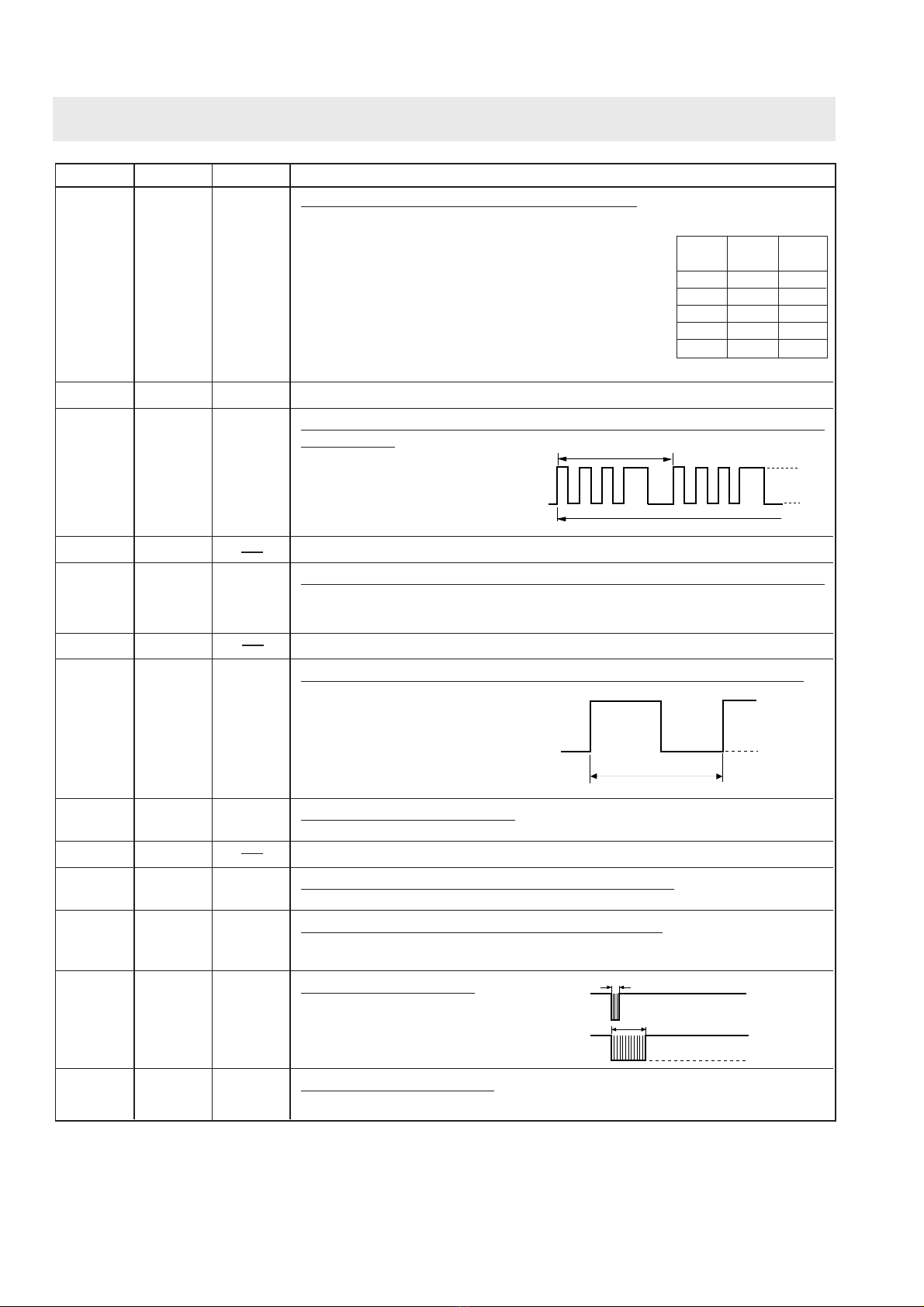
The I/O signal of the LSI(IZA882DR) are detailed in the following table.
Pin No. Signal I/O Description
DIGITAL ANALOGUE CONTROL PANEL

10
211M -
Pin No. Signal I/O Description ON/OFFtimeratioinMicro
cooking
(a. 32second time base)
MICRO ON OFF
COOK
100% 32sec. 0sec.
70% 24sec. 8sec.
50% 18sec. 14sec.
30% 12sec. 20sec.
10% 6sec. 26sec.
23 D6 OUT Magnetron high-voltage circuit driving signal.
Toturnonandoffthecookrelay(RY2).
In 100% POWER operation, the sig-
nals hold "L" level during microwave
cooking and "H" level while not cook-
ing.Inothercookingmodes(70%,50%,
30%, 10%) the signal turns to "H" level
and "L" level in repetition according to
the power level.
24 D7 IN/OUT Terminal not used.
25 D8 OUT Oven lamp, turntable motor and fan motor driving signal(Square Wave-
form : 50Hz).
To turn on and off shut-off relay
(RY1). The square waveform
voltage is delivered to the relay
(RY1) driving circuit and
relay(RY2) control circuit.
26 NC No connection terminal.
27 F0 IN Inputsignalwhichcommunicatesthedooropen/closeinformationtoLSI.
Door closed; "H" level signal.
Door opened; "L" level signal.
28 F1 Terminal not used.
29 F2 IN Signal to synchronize LSI with commercial power source frequency.
This is basic timing for all real time
processing of LSI.
30 F3 IN Signal coming from encoder.
Signal similar to INT. Pulse signals are input into F3.
31-32 NC No connection terminal.
33 XOUT OUT Internal clock oscillation frequency control output.
Output to control oscillation input of XOUT.
34 XIN IN Internal clock oscillation frequency input setting.
The internal clock frequency is set by inserting the ceramic filter oscillation
circuit with respect to XIN terminal.
35 CNTR OUT Signal to sound buzzer.
A: key touch sound.
B: Completion sound.
36 VDD IN Power source voltage: 0V.
The power source voltage to drive the LSI is input to VDD terminal.
20 msec
During cooking
H
L
20 msec
H : GND
L (-5V)
A
BH: GND
L: -5V
0.12 sec
2.4 sec
DIGITAL ANALOGUE CONTROL PANEL

11
211M -
SERVICING
ECB
ECB
Transistor
2SB1238
Transistor
DTA123ES
DTA143ES
DTD143ES
KRA101M
KRA222M
1. Precautions for Handling Electronic Components
This unit uses CMOS LSI in the integral part of the
circuits. When handling these parts, the following
precautions should be strictly followed. CMOS LSI have
extremely high impedance at its input and output
terminals. For this reason, it is easily influenced by the
surrounding high voltage power source, static electricity
charge in clothes, etc., and sometimes it is not fully
protected by the built-in protection circuit.
In order to protect CMOS LSI.
1) When storing and transporting, thoroughly wrap
them in aluminium foil. Also wrap PW boards
containing them in aluminium foil.
2) When soldering, ground the technician as shown in
the figure and use grounded soldering iron and work
table.
approx. 1M ohm
2. Shapes of Electronic Components
3. Servicing of Touch Control Panel
We describe the procedures to permit servicing of the
touch control panel of the microwave oven and the
precautions you must take when doing so.
To perform the servicing, power to the touch control
panel is available either from the power line of the oven
itself or from an external power source.
(1) Servicing the touch control panel with power
supply of the oven :
CAUTION:
THE HIGH VOLTAGE TRANSFORMER OF THE
MICROWAVE OVEN IS STILL LIVE DURING
SERVICING AND PRESENTS A HAZARD .
Therefore, when checking the performance of the
touch control panel, put the outer cabinet on the
oven to avoid touching the high voltage transformer,
or unplug the primary terminal (connector) of the
high voltage transformer to turn it off; the end of
such connector must be insulated with an insulating
tape. After servicing, be sure to replace the leads to
their original locations.
A. On some models, the power supply cord
between the touch control panel and the oven
itself is so short that the two can't be separated.
For those models, check and repair all the
DIGITAL ANALOGUE CONTROL PANEL
controls (sensor-related ones included) of the
touch control panel while keeping it connected
to the oven.
B. On some models, the power supply cord
between the touch control panel and the oven
proper is so long enough that they may be
separated from each other. For those models,
therefore, it is possible to check and repair the
controls of the touch control panel while keeping
it apart from the oven proper; in this case you
must short both ends of the door sensing switch
(on PWB) of the touch control panel with a
jumper, which brings about an operational state
that is equivalent to the oven door being closed.
As for the sensor-related controls of the touch
control panel, checking them is possible if the
dummy resistor(s) with resistance equal to that
of the controls are used.
(2) Servicing the touch control panel with power
supply from an external power source:
Disconnect the touch control panel completely from
the oven proper, and short both ends of the door
sensing switch (on PWB) of the touch control panel,
which brings about an operational state that is
equivalent to the oven door being closed. Connect
an external power source to the power input
terminal of the touch control panel, then it is
possible to check and repair the controls of the
touch control panel; it is also possible to check the
sensor-related controls of the touch control panel by
using the dummy resistor(s).
4. Servicing Tools
Tools required to service the touch control panel
assembly.
1) Soldering iron: 30W
(It is recommended to use a soldering iron with a
grounding terminal.)
2) Oscilloscope: Single beam, frequency range: DC -
10MHz type or more advanced model.
3) Others: Hand tools
5. Other Precautions
1) Before turning on the power source of the control
unit, remove the aluminium foil applied for
preventing static electricity.
2) Connect the connector of the key unit to the control
unit being sure that the lead wires are not twisted.
3) After aluminium foil is removed, be careful that
abnormal voltage due to static electricity etc. is not
applied to the input or output terminals.
4) Attach connectors, electrolytic capacitors, etc. to
PWB, making sure that all connections are tight.
5) Be sure to use specified components where high
precision is required.

12
211M -
DOOR REPLACEMENT
1. CARRY OUT 3D CHECKS.
2. Remove choke cover taking care not to break
clips by inserting an iron plate (thickness of about
0.5mm) or flat type screw driver into the gap between
the choke cover and door panel to free the engaged
part.
3. Remove door assembly by lifting and easing
it forward.
4. On re-installation make sure the door is
parallel with the bottom line of the oven face
plate and the latch head pass through the
latch holes correctly.
5. CARRY OUT 4R CHECKS.
NOTE : After any service to the door, the
approved microwave survey meter should be
used to assure in compliance with proper
microwave radiation standards.
DOOR ASSEMBLY
OUTER CASE
CABINET
LATCH HEADS
Figure C-6. Door Assembly Replacement and
Adjustment
COMPONENT REPLACEMENT
OUTER DOOR FILM
INNER DOOR FILM
Removal
1. Tear the door film from the door panel.
2. Now the door film is free.
Installation
1. Tear away the backing film.
2. Put the pasted side of the door film on the door
panel.
Removal
1. Remove the door film from the clips on the door frame.
Installation
1. Attach the door film to the clips on the door frame.
Finger tab
Door film Backing film
LATCH HEAD REMOVAL
1. Remove the choke as described in door
replacement.
2. Unhook the spring and lift the latch head clear.
3. Replacement, the reverse of the above.
MONITORED LATCH SWITCH, LATCH
SWITCH, AND MONITOR SWITCH REMOVAL
1. CARRY OUT 3D CHECKS.
2. Disconnect the leads from all switches.
3. Remove the one (1) screw holding the latch hook to the
oven cavity.
4. Remove the latch hook.
5. Push the retaining tab slightly and remove the switch.
Figure C-4. Switches
LATCH HOOK
SW3: STOP
SWITCH
SW1: MONITORED
LATCH SWITCH
SW2: MONITOR
SWITCH
Tab
Post
Tab
Tab
Post
Post

13
211M -
NOTE: INDICATES COMPONENTS
WITH POTENTIALS ABOVE
250V.
*
CIRCUIT SUBJECT TO
CHANGE
WITHOUT NOTICE.
DOOR CLOSED
COOK OFF
MICROWAVE CONDITION
SCHEMATIC DIAGRAM
BLU /18 BRN /18
G-Y /18
0. 22 µF /250V
NOISE FILTER
UNIT
0. 0033 µF /250V 0. 0033 µF /250V
10M/0 .5W
VRS1
RY2
RY2
RY1
A1
FAN
MOTOR
OVEN
LIGHT
TURNTABLE
MOTOR
FM
OL
TTM
B1
B2
COM
NO
COM
POWER TRANSFORMER WITH 150 C *
THERMOSTAT IN PRIMARY WINDING
MAGNETRON *H.V. RECTIFIER *
R-211()M 0. 88µF 2100VAC
R-211() 0. 91µF 2100VAC
H.V. CAPACITOR *
NO NO
STOP
SWITCH
SW3
MONITOR
SWITCH
SW2
MONIT'D
LATCH
SWITCH
SW1
NO
NO
A5 A3
T1
F1
680KΩ/0. 5W
OVEN
THERMAL
CUT-OUT
125 C
NOSIE SUPPRESSION COIL
EARTH
R-211 () M 230-240V~50Hz
R-211 () 230V~50Hz
LN

14
211M -
Figure S-1. Pictorial Diagram
NOTE: Most of the terminals are
Positive - Lock Type.
WIRING DIAGRAM
H.V COMPONENTS
TRANSFORMER
H.V
OVEN
THERMAL
POWER CORD
UNIT
NOISE
FAN
LAMP
MONITOR
SW2:
SWITCH
RELAY 2 SW3:
STOP
SW1:
SWITCH
LATCH
CONTROL
PANEL
H.V
RECTIFIER
H.V CAPACITOR
MAGNETRON
BLU
RED
WHT
MOTOR
TURNTABLE
CUT-OUT
SWITCH
CN-A
CN-B
MONITORED
OVEN MOTOR FILTER
WHT
WHT
WHT
BLU
BLU
RED
RED
BLU
WHT
WHT
RED
WHT
WHT
WHT
RED
RED
BLU
WHT
BLU
WHT
WHT
WHT
WHT
BLU
BLU
BLU
BLU
BLU
BLU
BLU
BLU
LN
BLU
BRN
G/Y
LIVE
NEUTRAL
EARTH

15
211M -
WIRING DIAGRAM
+
–
+
–
+
–
–
+
R50 R4 2k 1/2w
R6 4.7k
VRS1
10G471K
R7 10k
R20 4.7k
R10 1k 1/2w
ZD3 HZ12A3
R30 4.7k
R31 47k
D30 SWITCH
AC
OVEN LAMP
FAN MOTOR
TURNTABLE
MOTOR
HIGH
VOLTAGE
TRANSFORMER
D20
D22D21
(JC)
(JD)
R40 3.3k
SP1
ZD1 HZ6A3
ZD2 HZ4A2
I-1 M34225M1
R5 4.7k
C3
C6
D5
R63 100k
R62 100k
R60 4.7k
C61
SW1
CBA
C60
R61 4.7k
Q50
VR1
WH-A ab
c
d
(JA)
C2 0.1µ/50v
C20 0.1µ/50v
C21 10µ/35v
C4 47µ/16 v
CF1
4MHz
C5 0.1µ/50v
C30
C1 470µ/35v
(JB)
KRA222M
Q51
KRA222M
Q52
KRA222M
R1 100 2w
D1-D4
IN4005E
D1 D3
T1
(J1)
CN-A
AC
A 5
A 1
A 3
NO
COM
B 1
B 2
(A)
D4
D2
Q1 2SB1238
Q2
DTA123ES 0V
Q40
KRA101M
Q20
KRA101M
Q10 2SB1238
: IF NOT SPECIFIED 1/4w ±5%
: IF NOT SPECIFIED 1SS270A
: IF NOT SPECIFIED 0.01µF / 16v
RY1
(A)
RY2
Q21
DTD143ES
Q22
DTA143ES
Q53
KRA222M
150LD1LD7LD13LD19
LD2LD8LD14LD20
LD3LD9LD15LD21
LD4LD10LD16LD22
LD5LD11LD17LD23
LD6LD12LD18LD24
150
150
150
150
150
R51
R52
R53
R54
R55
1RST
2INT
3AVSS
4VREF
VDD
5K0
6K1
7AVDD
8NC
9S0
10
36
CNTR 35
XIN 34
XOUT 33
NC 32
NC 31
F3 30
F2 29
F1 28
F0 27
NC 26
D8 25
D7 24
D6 23
D5 22
D4 21
D3 20
D2 19
S1
11 S2
12 S3
13 NC
14 NC
15 D0
16 D1
17 CNVS
18 VSS
VC
Figure S-2. Control Panel Circuit

16
211M -
LD1
LD2
LD3
LD4
LD5 LD6 LD7 LD8 LD9
LD10
LD11
LD12
LD13
LD14
LD15
LD16
LD18
LD19
LD20
C61
(JA)
30
B
B
E
E
Q21
Q1
R1
C1
C6
36
D20
D23
D22
D21
R21
(J1)
R6
R7
(JD) 41
WH - A
WH - A
RY3
RY2
33 R30
R20
C4
C5
C21
,F
LD21
LD22
LD23
LD24 LD17
SW1
R60
R61
R63
7
8
12
11 26
27 D5
D30
R31
R5
R4
R40
R10
ZD1
ZD3
39
C2 D4
D3
RY1 VRS1
VR1
CN - A
D2
D1 T1
S
P
15
(JC)
R22
40
(JE)
ZD2
B
B
B
B
B
E
E
E
E
GRILL MICRO
DIP
E
Q2
Q40
Q22
Q20
Q10
CN - B
Q23
C20
SP1
C30
CF1
28
29
31 35
38
34
1
2
37
32
C3
(JB)
25
24
23
22
21
20
19
13
14
15
16
17
18
Q50
Q51
Q52
Q53
E
E
E
E
R50
R51
R52
R53
R54
R55
R62
C60
10
B
B
B
B
9
1
2
3
4
5
ABC
6
Figure S-3. Printed Wiring Board
WIRING DIAGRAM

17
211M -
Note: The parts marked “ *” are used in voltage more than 250V. The parts marked ∆may cause undue microwave exposure
“§” MARK: SPARE PARTS-DELIVERY SECTION
ELECTRICAL PARTS
REF NO PART NO S DESCRIPTION Q'TY CODE
1-1 RH-DZA048WRE0 U H.V. rectifier 1 AM *
1-2 FPWBFA308WRE1 U Noise filter 1 AQ
1-3 QACCBA030WRE2 U Power supply cord 1 AQ
1-4 RV-MZA270WRE0 U Magnetron 1 BG *∆
1-5 RC-QZA221WRE0 U High voltage capacitor 1 AT
1-6 QSW-MA110WRE0 J Monitored latch switch/Stop switch 2 AK
1-7 QSW-MA112WRE0 J Monitor swith 1 AN
1-8 RMOTEA360WRE0 U Fan motor 1 AU
1-9 QFS-CA024WREO U Fuse F8A 1 AC
1-10 RLMPTA066WRE0 U Oven lamp 1 AK
1-11 FMOTDA056WRKO J Turntable motor assy 1 AR
1-13 RTHM-A096WRE0 U Thermal cut-out 125°C (Oven) 1 AL
1-14 RTRN-A009UREO U Power transformer 1 BH *
PART LIST
CABINET PARTS
REF NO PART NO S DESCRIPTION Q'TY CODE
2-1 GCABUA001URP0 U Outer case cabinet (B) 1 AT ∆
2-1 GCABUA573WRT0 U Outer case cabinet (W) 1 AT ∆
2-1 GCABUA003URP0 U Outer case cabinet (G) 1 AT ∆
2-1 GCABUA009URP0 U Outer case cabinet (BL) 1 AT ∆
2-2 GLEGPA057WRE0 U Foot 2 AB
CONTROL PANEL PARTS
REF NO PART NO S DESCRIPTION Q'TY CODE
3- 1 DPWBFB785WRK0 J Control unit 1
3- 1A QCNCMA430DRE0 J 3-pin connector (CN-A) 1 AG
3- 1B QCNCMA414DRE0 J 2-pin connector (CN-B) 1 AB
3- 1C FW-VZA234DRE0 J Lead wire (WH-A) 1 AD
3- 1D LHLD-A004URF0 J LED holder 1 AC
C1 VCEAB31VW477M J Capacitor 470 uF 35V 1 AC
C2 RC-KZA087DRE0 J Capacitor 0.1 uF 50V 1 AA
C3 VCKYD11CY103N J Capacitor 0.01 uF 16V 1 AA
C4 VCEAB31CW476M J Capacitor 47 uF 16V 1 AA
C5 RC-KZA087DRE0 J Capacitor 0.1 uF 50V 1 AA
C6 VCKYD11CY103N J Capacitor 0.01 uF 16V 1 AA
C20 VCEAB31HW104M J Capacitor 0.1 uF 50V 1 AM
C21 VCEAB31VW106M J Capacitor 10 uF 35V 1 AA
C30 VCKYD11CY103N J Capacitor 0.01 uF 16V 1 AA
C60-61 VCKYD11CY103N J Capacitor 0.01 uF 16V 2 AA
CF1 RCRS-A012DRE0 J Ceramic resonator (CST4.00MGW) 1 AD
D1-4 VHD1N4005E1-2 J Diode (1N4005E) 4 AB
D5 VHD1SS270A/-1 J Diode (1SS270ATA) 1 AA
D20-22 VHD1SS270A/-1 J Diode (1SS270ATA) 3 AA
D30 VHD1SS270A/-1 J Diode (1SS270ATA) 1 AA
I-1 RH-IZA882DRE0 J LSI 1 AK
LD1-24 VHPLTL1CHE/-3 J Light emitting diode (LED) 24 AD
Q1 VS2SB1238//-3 J Transistor (2SB1238) 1 AA
Q2 VSDTA123ES/-3 J Transistor (DTA123ES) 1 AA
Q10 VS2SB1238//-3 J Transistor (2SB1238) 1 AA
Q20 VSKRA101M//-3 J Transistor (KRA101M) 1 AB
Q21 VSDTD143ES/-3 J Transistor (DTD143ES) 1 AC
Q22 VSDTA143ES/1B J Transistor (DTA143ES) 1 AA
Q40 VSKRA101M//-3 J Transistor (KRA101M) 1 AB
Q50-53 VSKRA222M//-3 J Transistor (KRA222M) 4 AB
R1 VRS-L63DA101J J Resistor 100 ohm 2W 1 AD
R4 VRD-B12HF202J J Resistor 2.0k ohm 1/2W 1 AB
R5-6 VRD-B12EF472J J Resistor 4.7k ohm 1/4W 2 AA
R7 VRD-B12EF103J J Resistor 10k ohm 1/4W 1 AA
R10 VRD-B12HF102J J Resistor 1.0k ohm 1/2W 1 AA

18
211M -
PART LIST
CONTROL PANEL PARTS
REF NO PART NO S DESCRIPTION Q'TY CODE
R20 VRD-B12EF472J J Resistor 4.7k ohm 1/4W 1 AA
R30 VRD-B12EF472J J Resistor 4.7k ohm 1/4W 1 AA
R31 VRD-B12EF473J J Resistor 47k ohm 1/4W 1 AA
R40 VRD-B12EF332J J Resistor 3.3k ohm 1/4W 1 AA
R50-55 VRD-B12EF151J J Resistor 150 ohm 1/4W 6 AA
R60-61 VRD-B12EF472J J Resistor 4.7k ohm 1/4W 2 AA
R62-63 VRD-B12EF104J J Resistor 100k ohm 1/4W 2 AA
RY1 RRLY-A111DRE0 J Relay (JV12S-KT) 1 AL
RY2 RRLY-A105DRE0 J Relay (OMIF-S-112LM) 1 AN
SP1 RALM-A014DRE0 J Buzzer (PKM22EPT) 1 AG
SW1 RVR-BA018WRE0 J Rotary encoder 1 AL
T1 RTRNPA121DRE0 J Transformer 1 AT
VR1 RVR-BA013DRE0 J Potention meter 1 AF
VRS1 RH-VZA032DRE0 J Varistor (10G471K) 1 AE
ZD1 VHEHZ6A3///-1 J Zener diode (HZ6A3) 1 AC
ZD2 VHEHZ4A2///-1 J Zener diode (HZ4A2) 1 AA
ZD3 VHEHZ12A3//-1 J Zener diode (HZ12A3) 1 AA
3- 2 HPNLCG001URR0 U Control panel [R-211(G)M] 1 AP
3- 2 HPNLCL001URR0 U Control panel [R-211(BL)M] 1 AP
3- 2 HPNLCW002URR0 U Control panel [R-211(W)M] 1 AP
3- 2 HPNLCB001URR0 U Control panel print (R-211(B)M) 1 AP
3- 3 JBTN-A011URF0 U Open button [R-211(G)M] 1 AE
3- 3 JBTN-A073URF0 U Open button [R-211(BL)M] 1 AE
3- 3 JBTN-A001URF0 U Open button (R-211(B)M) 1 AE
3- 3 JBTN-B009WRF0 U Open button [R-211(W)M] 1 AE
3- 4 MSPRCA045WRE0 U Spring 2 AA
3- 5 GMADIA011URR0 U Timer display plate 1 AE
3- 6 JKNBKG001URF0 U Timer knob [R-211(G)M] 1 AE
3- 6 JKNBKL001URF0 U Timer knob [R-211(BL)M] 1 AE
3- 6 JKNBKW001URF0 U Timer knob [R-211(W)M] 1 AE
3- 6 JKNBKB001URF0 U Timer knob (R-211(B)M) 1 AE
3- 7 JKNBKG002URF0 U Vari knob [R-211(G)M] 1 AD
3- 7 JKNBKL002URF0 U Vari knob [R-211(BL)M] 1 AD
3- 7 JKNBKB002URF0 U Vari knob (R-211(B)M) 1 AD
3- 7 JKNBKW002URF0 U Vari knob (R-211(W)M) 1 AD
3- 8 LSTPPA008URF0 U Stopper 1 AB
3- 9 XEPSD30P10XS0 U Self tapping screw 5 AA
3- 10 PCLI-A001URE0 U Harness clip 1 AC
OVEN PARTS
REF NO PART NO S DESCRIPTION Q'TY CODE
4-1 DOVN-A005URT0 U Oven cavity 1 BA
4-2 LBNDKA111WRP0 U Capacitor holder 1 AD
4-3 PHOK-A092WRF4 U Latch hook 1 AH
4-4 NFANJA029WRE0 U Fan blade 1 AM
4-5 PDUC-A638WRF2 U Fan duct 1 AE
4-6 LANGFA169WRP5 U Chassis support 1 AE
4-7 PPACGA126WRE0 U Seal packing 1 AC
4-8 MLEVFA078WRF0 U Open lever 1 AE
4-9 PCOVPA309WRE0 U Waveguide cover 1 AC
4-10 PDUC-A581WRF3 U Air intake duct 1 AE
4-11 GDAI-A280WRP1 U Base plate 1 AQ
4-12 PCUSGA001URP0 U HVT cushion 1 AB
4-13 PSPAGA001WRE0 U Vibration Proof Cushion 1 AA

19
211M -
Note: The parts marked “*” are used in voltage more than 250V. The parts marked ∆may cause undue microwave exposure
“§” MARK: SPARE PARTS-DELIVERY SECTION
DOOR PARTS
REF NO PART NO S DESCRIPTION Q'TY CODE
5 CDORFB001URK0 U Door assembly (B) 1 BB ∆
5 CDORFW001URK0 U Door assembly (W) 1 BB ∆
5 CDORFG002URK0 U Door assembly (G) 1 BB ∆
5 CDORFL001URK0 U Door assembly (BL) 1 BB ∆
5-1 FDORFA299WRT0 U Door panel assembly 1 AU
5-2 GCOVHA366WRF0 U Choke cover 1 AG
5-3 GWAKPA001URF0 U Door frame (B) 1 AP ∆
5-3 GWAKPA427WRF0 U Door frame (W) 1 AP ∆
5-3 GWAKPA009URF0 U Door frame (G) 1 AP ∆
5-3 GWAKPA025URF0 U Door frame (BL) 1 AP ∆
5-4 PSHEPA560WRE1 U Outer sealer film 1 AE
5-5 LSTPPA158WRF0 U Latch head 1 AD
5-6 MSPRTA141WRE0 U Latch spring 1 AA
5-7 PSHEPA482WRE0 U Inner Sealer film 1 AH
5-8 XEBSD30P06000 U Self tapping screw 4 AA
HOW TO ORDER REPLACEMENT PARTS
To have your order filled promptly and correctly, please furnish the following information.
1. MODEL NUMBER 2. REF. NO.
3. PART NO. 4. DESCRIPTION
PART LIST
MISCELLANEOUS
REF NO PART NO S DESCRIPTION Q'TY CODE
6-1 FROLPA070WRK2 U Roller stay 1 AM
6-2 NTNT-A034WRF0 U Turntable 1 AN
6-3 TINS-A069URRO U Operation Manual/Cookery book 1 AM
6-4 QW-QZA191WRE0 U H.V. wire A 1 AF *
6-5 QW-QZA001URE0 U H.V. wire B 1 AE *
6-6 FW-VZA041UREO U Main wire harness 1 AR
SCREW, NUT AND WASHER
REF NO PART NO S DESCRIPTION Q'TY CODE
7-1 XOTSD40P12RV0 J Screw 4mm x 12mm 12 AA
7-2 XHTSD40P08RV0 J Screw 4mm x 8mm 5 AA
7-3 LX-LZA011WRE0 U Rivet 1 AB
7-4 Not applicable to this model
7-5 XFPSD40P06000 J Screw 4mm x 8mm 2 AA
7-7 XOTSE40P12000 J Screw 4mm x 12mm (Chrome) 2 AA
7-7 XOTSF40P12000 J Screw 4mm x 12mm (Black) 2 AA
7-8 LX-CZA063WRE0 U HVT screw 4 AA
7-9 XHPSD40P08K00 J Screw 1 AA
7-10 LX-CZA030WRE0 J Screw 1 AA
7-11 LX-NZA026WRE0 U M4 Nyloc nut 1 AA
7-12 XOTSD40P10000 J Self tapping screw 2 AA

20
211M -
NOTE: In the event of removing the
turntable motor cover this part should be
refitted using screw connection:
LX-CZA030WRE0
CABINET AND UNIT CHASSIS PARTS
EXPLODED ILLUSTRATION
2-1
7-7
7-1
1-10
4-10
1-4
7-2
1-3
1-13
4-1
4-9
4-7
7-5 4-8
1-11
4-3
1-14
4-11
7-1 2-2
7-1 7-1 4-13
2-2
7-8
7-2
1-6
4-12
7-1 1-5
x4
x2
6-1
1-1
4-2
6-2
7-9
7-2
7-5
7-1
7-12
1-7
1-6
7-12
7-7
7-1
7-1
7-11
4-6
1-9
1-2
3-10
1-8
7-2
7-2
4-4
4-5
7-3
This manual suits for next models
3
Table of contents
Other Sharp Microwave Oven manuals

Sharp
Sharp R-798-A Instruction Manual

Sharp
Sharp R-408J User manual

Sharp
Sharp YC-GC52FE User manual

Sharp
Sharp R-209 Instruction Manual

Sharp
Sharp R-390AW User manual

Sharp
Sharp R1871T User manual

Sharp
Sharp R-308CK User manual

Sharp
Sharp SMD2470AS User manual

Sharp
Sharp R98STM-AA User manual

Sharp
Sharp R-7370 User manual

Sharp
Sharp R-260L Use and care manual

Sharp
Sharp Carousel R-1870 User manual

Sharp
Sharp R-3S68 User manual

Sharp
Sharp R-270 User manual

Sharp
Sharp Carousel R-7A54 User manual

Sharp
Sharp R-23AM User manual

Sharp
Sharp EBR-90GKST User manual

Sharp
Sharp R-26ST Instruction Manual

Sharp
Sharp R-899P User manual

Sharp
Sharp R-247 Instruction Manual