Sharp R-318BK User manual

R-318BK
TABLE OF CONTENTS Page
PRECAUTIONS TO BE OBSERVED BEFORE AND DURING SERVICING TO
AVOID POSSIBLE EXPOSURE TO EXCESSIVE MICROWAVE ENERGY ...................INSIDE FRONT COVER
BEFORE SERVICING ......................................................................................................INSIDE FRONT COVER
WARNING TO SERVICE PERSONNEL................................................................................................................1
MICROWAVE MEASUREMENT PROCEDURE ...................................................................................................2
FOREWORD AND WARNING...............................................................................................................................3
PRODUCT SPECIFICATIONS ..............................................................................................................................4
SCHEMATIC DIAGRAM ........................................................................................................................................5
TEST PROCEDURE ..............................................................................................................................................6
POWER UNIT CIRCUIT ........................................................................................................................................7
CPU UNIT CIRCUIT ..............................................................................................................................................8
PRINTED WIRING BOARD ...................................................................................................................................9
PARTS LIST ........................................................................................................................................................10
PACKING AND ACCESSORIES .........................................................................................................................14
S915R318BPK/
MICROWAVE OVEN
MODEL R-318BK
In the interest of user-safety the oven should be restored to its original
condition and only parts identical to those specified should be used.
WARNING TO SERVICE PERSONNEL: Microwave ovens con-
tain circuitry capable of producing very high voltage and
current, contact with following parts may result in a severe,
possibly fatal, electrical shock. (High Voltage Capacitor, High
VoltagePowerTransformer,Magnetron,HighVoltageRectifier
Assembly, High Voltage Harness etc..)
SHARP CORPORATION This document has been published to be used for after
sales service only.
The contents are subject to change without notice.
SUPPLEMENTAL SERVICE MANUAL
This is a supplemental Service Manual for Model R-318BK. This model is quite similar to base
model R-320BK. Use this supplemental manual together with the Base Model Service Manual
(Refer No. is S2805R320BPW/) for complete operation, service information, etc..
BAKED
POTATO
GROUND
MEAT CHICKEN
BREAST
FRESH/
SEAFOOD
GROUND
MEAT
KITCHEN
TIMER MINUTE
PLUS
AUTO START
CLOCK
CHICKEN
PIECES
STEAKS/
CHOPS
POPCORN
FRESH VEGETABLE
FRESH ROLL FROZEN ROLL
FROZEN ENTREES
REHEAT
SENSOR COOK
INSTANT ACTION
COMPU DEFROST
TO ADJUST QUANTITY . TOUCH PAD AGAIN
POWER
LEVEL START
STOP
CLEAR

R-318BK
PRECAUTIONSTO BE OBSERVED BEFORE AND
DURING SERVICINGTO AVOID POSSIBLE
EXPOSURETO EXCESSIVE MICROWAVE
ENERGY
(a) Do not operate or allow the oven to be operated with the door open.
(b) Make the following safety checks on all ovens to be serviced before activating the magnetron or other
microwave source, and make repairs as necessary: (1) interlock operation, (2) proper door closing, (3)
seal and sealing surfaces (arcing, wear, and other damage), (4) damage to or loosening of hinges and
latches, (5) evidence of dropping or abuse.
(c) Before turning on microwave power for any service test or inspection within the microwave generating
compartments, check the magnetron, wave guide or transmission line, and cavity for proper alignment,
integrity, and connections.
(d) Any defective or misadjusted components in the interlock, monitor, door seal, and microwave
generation and transmission systems shall be repaired, replaced, or adjusted by procedures described
in this manual before the oven is released to the owner.
(e) A microwave leakage check to verify compliance with the Federal Performance Standard should be
performed on each oven prior to release to the owner.
BEFORE SERVICING
Before servicing an operative unit, perform a microwave emission check as per the Microwave
Measurement Procedure outlined in this service manual.
If microwave emissions level is in excess of the specified limit, contact SHARP ELECTRONICS
CORPORATION immediately @1-800-237-4277.
If the unit operates with the door open, service person should 1) tell the user not to operate the oven
and 2) contact SHARP ELECTRONICS CORPORATION and The Food and Drug Administration's
Center for Devices and Radiological Health immediately.
ServicepersonnelshouldinformSHARPELECTRONICSCORPORATIONofanycertifiedunitfound
with emissions in excess of 4mW/cm2. The owner of the unit should be instructed not to use the unit
until the oven has been brought into compliance.

1
R-318BK
WARNINGTO SERVICE PERSONNEL
Microwave ovens contain circuitry capable of pro-
ducing very high voltage and current, contact with
following parts
may result in a severe, possibly
fatal, electrical shock.
(Example)
HighVoltageCapacitor,HighVoltagePowerTrans-
former,Magnetron,HighVoltageRectifierAssem-
bly, High Voltage Harness etc..
Read the Service Manual carefully and follow all
instructions.
Before Servicing
1. Disconnect the power supply cord , and then
remove outer case.
2. Open the door and block it open.
3. Discharge high voltage capacitor.
WARNING:RISK OF ELECTRIC SHOCK.
DISCHARGE THE HIGH-VOLTAGE
CAPACITOR BEFORE SERVICING.
The high-voltage capacitor remains charged about 60
secondsaftertheovenhasbeenswitchedoff.Waitfor60
secondsandthenshort-circuittheconnectionofthehigh-
voltagecapacitor (thatis theconnectingleadofthe high-
voltage rectifier) against the chassis with the use of an
insulated screwdriver.
Whenever troubleshooting is performed the power supply
mustbedisconnected.Itmayin,somecases,benecessary
to connect the power supply after the outer case has been
removed, in this event,
1. Disconnect the power supply cord, and then remove
outer case.
2. Open the door and block it open.
3. Discharge high voltage capacitor.
4. Disconnect the leads to the primary of the power
transformer.
5. Ensure that the leads remain isolated from other
components and oven chassis by using insulation tape.
6. After that procedure, reconnect the power supply cord.
When the testing is completed,
1. Disconnect the power supply cord, and then remove
outer case.
2. Open the door and block it open.
3. Discharge high voltage capacitor.
4. Reconnect the leads to the primary of the power
transformer.
5. Reinstall the outer case (cabinet).
6. Reconnectthepower supplycord afterthe outercase is
installed.
7. Run the oven and check all functions.
After repairing
1. Reconnect all leads removed from components during
testing.
2. Reinstall the outer case (cabinet).
3. Reconnectthepower supplycord afterthe outercase is
installed.
4. Run the oven and check all functions.
Microwave ovens should not be run empty. To test for the
presence of microwave energy within a cavity, place a cup
of cold water on the oven turntable, close the door and set
the power to HIGH and set the microwave timer for two (2)
minutes. When the two minutes has elapsed (timer at zero)
carefully check that the water is now hot. If the water
remainscoldcarryoutBeforeServicingprocedureandre-
examine the connections to the component being tested.
When all service work is completed and the oven is fully
assembled,themicrowavepoweroutputshouldbechecked
and microwave leakage test should be carried out.
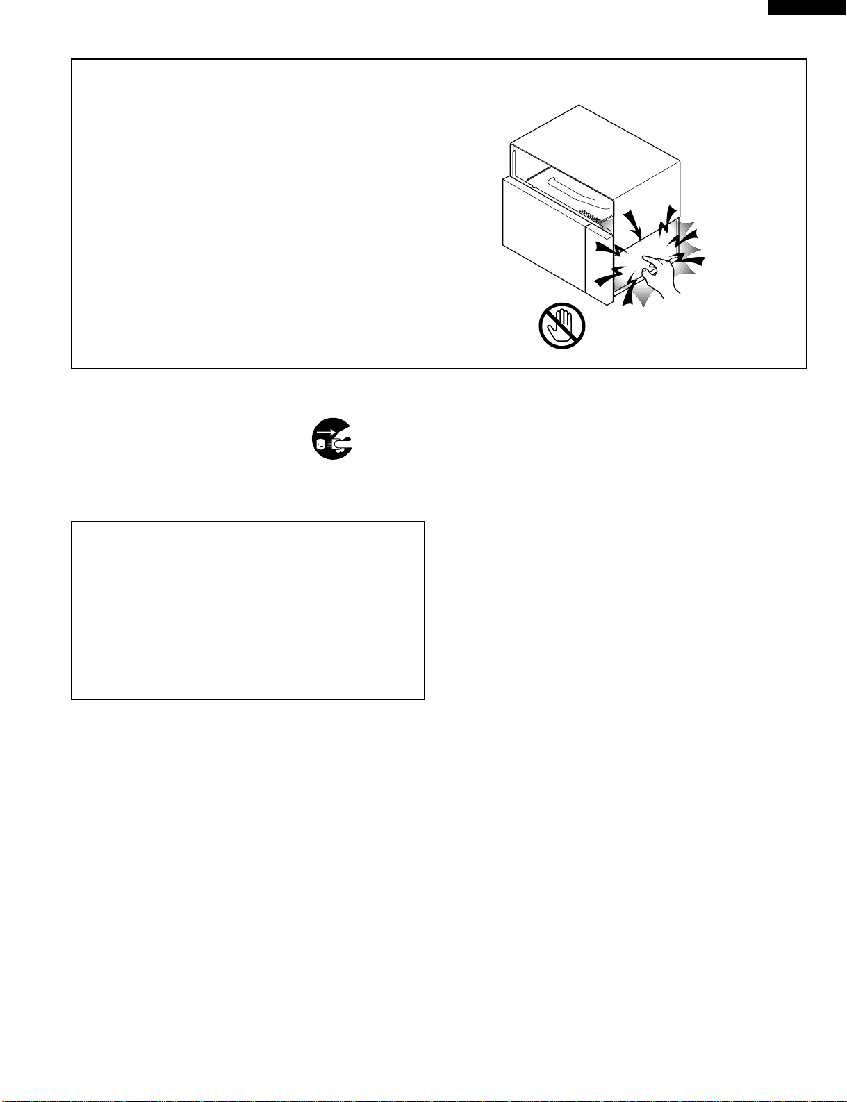
Don't Touch !
Danger High Voltage

2
R-318BK
MICROWAVE MEASUREMENT PROCEDURE
A. Requirements:
1) Microwave leakage limit (Power density limit): The power density of microwave radiation emitted by a microwave oven
shouldnotexceed1mW/cm2atanypoint5cmormorefromtheexternalsurfaceoftheoven,measuredpriortoacquisition
bya purchaser,andthereafter (throughtheuseful lifeof theoven),5 mW/cm2atany point5cmor morefromthe external
surface of the oven.
2) Safety interlock switches Primary interlock relay and door sensing switch shall prevent microwave radiation emission in
excess of the requirement as above mentioned, secondary interlock switch shall prevent microwave radiation emission
in excess of 5 mW/cm2at any point 5cm or more from the external surface of the oven.
B. Preparation for testing:
Before beginning the actual measurement of leakage, proceed as follows:
1) Make sure that the actual instrument is operating normally as specified in its instruction booklet.
Important:
Surveyinstruments that complywith therequirement forinstrumentation asprescribed bythe performancestandard
for microwave ovens, 21 CFR 1030.10(c)(3)(i), must be used for testing.
2) Place the oven tray in the oven cavity.
3) Place the load of 275±15 ml (9.8 oz) of tap water initially at 20±5˚C (68˚F) in the center of the oven cavity.
The water container shall be a low form of 600 ml (20 oz) beaker with an inside diameter of approx. 8.5 cm (3-1/2 in.)
and made of an electrically nonconductive material such as glass or plastic.
Theplacingof thisstandard loadin the ovenis importantnot onlyto protect theoven, butalso toinsure that anyleakage
is measured accurately.
4) Set the cooking control on Full Power Cooking Mode
5) Close the door and select a cook cycle of several minutes. If the water begins to boil before the survey is completed,
replace it with 275 ml of cool water.
C. Leakage test:
Closed-door leakage test (microwave measurement)
1) Grasptheprobeofthesurveyinstrumentandholditperpendiculartothegapbetweenthedoorandthebodyoftheoven.
2) Move the probe slowly, not faster than 1 in./sec. (2.5 cm/sec.) along the gap, watching for the maximum indication on
the meter.
3) Checkforleakageatthedoorscreen,sheetmetalseamsandotheraccessiblepositionswherethecontinuityofthemetal
has been breached (eg., around the switches, indicator, and vents).
Whiletestingforleakagearoundthedoorpullthedoorawayfromthefrontoftheovenasfarasispermittedbytheclosed
latch assembly.
4) Measure carefully at the point of highest leakage and make sure that the highest leakage is no greater than 4mW/cm2,
and that the secondary interlock switch does turn the oven OFF before any door movement.
NOTE: After servicing, record data on service invoice and microwave leakage report.

3
R-318BK
SHARP ELECTRONICS CORPORATION
SHARP PLAZA, MAHWAH,
NEW JERSEY 07430-2135
SERVICE MANUAL
MICROWAVE OVEN
R-318BK
FOREWORD
This Manual has been prepared to provide Sharp Electronics Corp. Service Personnel with Operation and Service
Information for the SHARP MICROWAVE OVEN, R-318BK.
The model R-318BK is quite similar to base model R-320BK (Refer No. is S2805R320BPW/).
It is recommended that service personnel carefully study the entire text of this manual and the base model's manual so
that they will be qualified to render satisfactory customer service.
Check the interlock switches and the door seal carefully. Special attention should be given to avoid electrical shock and
microwave radiation hazard.
WARNING
Never operate the oven until the following points are ensured.
(A) The door is tightly closed.
(B) The door brackets and hinges are not defective.
(C) The door packing is not damaged.
(D) The door is not deformed or warped.
(E) There is no other visible damage with the oven.
Servicing and repair work must be carried out only by trained service personnel.
DANGER
Certaininitialpartsareintentionallynotgroundedandpresentariskofelectricalshockonlyduringservicing.
Service personnel - Do not contact the following parts while the appliance is energized;
High Voltage Capacitor, Power Transformer, Magnetron, High Voltage Rectifier Assembly, High Voltage
Harness;
If provided, Vent Hood, Fan assembly, Cooling Fan Motor.
All the parts marked “*” on parts list are used at voltages more than 250V.
Removal of the outer wrap gives access to voltage above 250V.
All the parts marked “∆” on parts list may cause undue microwave exposure, by themselves, or when they are
damaged, loosened or removed.

4
R-318BK
ITEM DESCRIPTION
Power Requirements 120 Volts / 14 Amperes
60 Hertz
Single phase, 3 wire grounded
Power Output 1100 watts (IEC-705 TEST PROCEDURE)
Operating frequency of 2450MHz
Case Dimensions Width 20-1/2"
Height 11-7/8"
Depth 15-7/8"
Cooking Cavity Dimensions Width 13-3/4"
Height 8-3/8"
1.0 Cubic Feet Depth 14-7/8"
Control Complement Touch Control System
Clock ( 1:00 - 12:59 )
Timer (0 - 99 min. 99 seconds)
Microwave Power for Variable Cooking
Repetition Rate;
P-HI..................................................Full power throughout the cooking time
P-90 .................................................................... approx. 90% of Full Power
P-80 .................................................................... approx. 80% of Full Power
P-70 .................................................................... approx. 70% of Full Power
P-60 .................................................................... approx. 60% of Full Power
P-50 .................................................................... approx. 50% of Full Power
P-40 .................................................................... approx. 40% of Full Power
P-30 .................................................................... approx. 30% of Full Power
P-20 .................................................................... approx. 20% of Full Power
P-10 .................................................................... approx. 10% of Full Power
P-0 .................................................... No power throughout the cooking time
SENSOR COOK pads, INSTANT ACTION pads
COMPU DEFROST pads, Number selection pads
KITCHEN TIMER pad, AUTO START/CLOCK pad
MINUTE PLUS pad, POWER LEVEL pad
STOP/CLEAR pad, START pad
Oven Cavity Light Yes
Safety Standard UL Listed FCC Authorized
DHHS Rules, CFR, Title 21, Chapter 1, Subchapter J
SPECIFICATION

5
R-318BK
TOUCH CONTROL PANEL
BAKED
POTATO
GROUND
MEAT CHICKEN
BREAST
FRESH/
SEAFOOD
GROUND
MEAT
KITCHEN
TIMER MINUTE
PLUS
AUTO START
CLOCK
CHICKEN
PIECES
STEAKS/
CHOPS
POPCORN
FRESH VEGETABLES
FRESH ROLL FROZEN ROLL
FROZEN ENTREES
REHEAT
SENSOR COOK
INSTANT ACTION
COMPU DEFROST
TO ADJUST QUANTITY . TOUCH PAD AGAIN
POWER
LEVEL START
STOP
CLEAR
Figure O-1. Oven Schematic-Off Condition
SCHEMATIC
NOTE: CONDITION OF OVEN
1. DOOR CLOSED
2. CLOCK APPEARS ON DISPLAY
120V AC
60 Hz
OVEN
LAMP TURN-
TABLE
MOTOR FAN
MOTOR
POWER
TRANSFORMER
CAPACITOR 1.0µF
AC 2300V
MONITOR
SWITCH
RECTIFIER MAGNETRON
SECONDARY
INTERLOCK
SWITCH
TTM
OL FM
MONITOR
FUSE 20A
A1
A2
COM.
COM.N.O.
N.O.
DOOR
SENSING
SWITCH
(RY-1) (RY-2)
CONTROL UNIT
PRIMARY
INTERLOCK
RELAY
THERMAL
CUT-OUT (OVEN) THERMAL
CUT-OUT (MG.)
SH-B SH-A
GRN
F3
F1 F2
AH SENSOR

6
R-318BK
TEST PROCEDURES
PROCEDURE
LETTER COMPONENT TEST
J KEY UNIT TEST
TROUBLESHOOTING GUIDE
Nevertouch anypart inthe circuitwithyourhandoranuninsulatedtoolwhile thepower supplyis connected.
Whentroubleshootingthe microwaveoven,itis helpfultofollowtheSequenceofOperationinperforming thechecks.Many
ofthepossiblecausesoftroublewillrequirethataspecifictestbeperformed. Thesetestsaregivenaprocedureletter which
will be found in the "Test Procedure "section.
IMPORTANT: If the oven becomes inoperative because of a blown monitor fuse, check the monitor switch, relay (RY1)
primary interlock relay (RY2), door sensing switch and secondary interlock switch before replacing the
monitor fuse. If monitor fuse is replaced, the monitor switch must also be replaced. Use part FFS-
BA021WRK0 as an assembly.
IMPORTANT: Whenever troubleshooting is performed with the power supply cord disconnected. It may in, some cases,
be necessary to connect the power supply cord after the outer case has been removed, in this event,
1. Disconnect the power supply cord, and then remove outer case.
2. Open the door and block it open.
3. Discharge high voltage capacitor.
4. Disconnect the leads to the primary of the power transformer.
5. Ensurethatthe leadsremainisolatedfrom othercomponentsandovenchassisbyusinginsulationtape.
6. After that procedure, reconnect the power supply cord.
When the testing is completed
1. Disconnect the power supply cord, and then remove outer case.
2. Open the door and block it open.
3. Discharge high voltage capacitor.
4. Reconnect the leads to the primary of the power transformer.
5. Reinstall the outer case (cabinet).
6. Reconnect the power supply cord after the outer case is installed.
7. Run the oven and check all functions.
H BLOWN MONITOR FUSE TEST
1. Disconnect the power supply cord, and then remove outer case.
2. Open the door and block it open.
3. Discharge high voltage capacitor.
4. If the monitor fuse is blown when the door is opened, check the primary interlock relay, secondary
interlockswitchandmonitorswitchaccordingtothe"TESTPROCEDURE"forthoseswitchesbefore
replacing the blown monitor fuse.
CAUTION: BEFORE REPLACING A BLOWN MONITOR FUSE, TEST THE PRIMARY INTERLOCK
RELAY,SECONDARYINTERLOCKSWITCH,DOORSENSINGSWITCHANDMONITOR
SWITCH FOR PROPER OPERATION.
If the monitor fuse is blown by improper switch operation, the monitor fuse and monitor switch must
be replaced with "monitor fuse and monitor switch assembly" part number FFS-BA021WRK0, even
ifthe monitorswitch operatesnormally. Themonitor fuseand monitorswitch assemblyis comprised
of a 20 ampere fuse and switch.
5. Reconnect all leads removed from components during testing.
6. Reinstall the outer case (cabinet).
7. Reconnect the power supply cord after the outer case is installed.
8. Run the oven and check all functions.
1. Disconnect the power supply cord, and then remove outer case.
2. Open the door and block it open.
3. Discharge high voltage capacitor.

7
R-318BK
4. If the display fails to clear when the STOP/CLEAR pad is depressed, first verify the flat ribbon cable
ismakinggoodcontact,verifythatthedoorsensingswitch(stopswitch)operatesproperly;thatisthe
contacts are closed when the door is closed and open when the door is open. If the door sensing
switch (stop switch) is good, disconnect the flat ribbon cable that connects the key unit to the control
unitand makesure thedoor sensingswitch isclosed (eitherclose thedoor orshort thedoor sensing
switch connecter). Use the Key unit matrix indicated on the control panel schematic and place a
jumperwire betweenthepins thatcorrespondto theSTOP/CLEAR padmakingmomentary contact.
If the control unit responds by clearing with a beep the key unit is faulty and must be replaced. If the
control unit does not respond, it is faulty and must be replaced. If a specific pad does not respond,
the above method may be used (after
clearingthecontrolunit)todetermineif
the control unit or key pad is at fault.
5. Reconnect all leads removed from
components during testing.
6. Re-install the outer case (cabinet).
7. Reconnectthe power supplycord after
the outer case is installed.
8. Run the oven and check all functions.
54321
09876
STOP
CLEAR
AUTO
START
CLOCK
Chicken
breast
KITCHEN
TIMER
Fresh
Vegetables
Fish /
seafood
Ground meat
Ground meat
COMPU
DEFROST
Chicken
pieces
PopcornReheat
START
POWER
LEVEL
MINUTE
PLUS
Fresh
roll /
muffin
Frozen
roll /
muffin
Frozen
entrees
Baked
potato
Steaks /
chops
INSTANT
ACTION
G 8
G 9
G10
G11
G12
G 7 G 6 G 5 G 4 G 3 G 2 G 1
6
45
123
6
45
123
A
B
C
D
E
F
G
H
A
B
C
D
E
F
G
H
Figure S-2. Power Unit Circuit
+
–
+
–
+
–
A 1
A 2
C 1
C 2
C 3
C 4
C 5
C 6
C 7
C 8
C 9
SH-B
SH-A
T1
AC
AC
AC
MICRO
VA
GND
VC
INT
BUZZER
MICRO
DOOR
SWITCH
NOTE : IF NOT SPECIFIED, 1/4w ±5%
: IF NOT SPECIFIED, 1SS270A
TURNTABLE
MOTOR
OVEN LAMP
FAN
MOTOR TURNTABLE
MOTOR
OVEN LAMP
FAN
MOTOR
WH-1
R4 27
R5 4.7k
R2 680 1/2w
R6 3.3k
SP1
VRS1
C1 0.1µ/50v
C3 0.1µ/50v
ZD1
HZ16-1
C4 10µ/35v
C5
10µ/35v
R3 510
1/2w
C2 1000µ/35v
R1 2.4k
(J1)
D5
D3
D4 D2
D1
a
c
d
b
D6
RY1
D7
D8
RY2
Q2 2SB1238
2SB1238
Q1
D1-D4
11ES1
Q3 DTD143ES
V
R
V
R
V
R
V
A
LD1-LD5
LD1 LD2 LD3 LD4 LD5
N.O.
N.O.
COM
COM
14
3 6

8
R-318BK
6
45
123
6
45
123
A
B
C
D
E
F
G
H
A
B
C
D
E
F
G
H
Figure S-3. CPU Unit Circuit
28
29
27 C 1
C 2
C 3
26 C 0
25 S16
24 S15
23 S14
22 S13
21 S12
20 S11
19 S10
18 S 9
17 S 8
16 S 7
15 S 6
14 S 5
13 S19
12 S20
11 S21
10 S22
9 S23
8 S24
7 S25
6 S26
5S4
4S3
3S2
2S1
1S0
27
RESET
64
SEG10
28
P71 29
P70 30
XIN 31
XOUT
80
79
COM0
78
COM1
77
COM2
76
COM3
75
74
VREF
73
AVSS
SEG8
41
63
62
SEG11
61
SEG12
60
SEG13
59
SEG14
58
SEG15
57
SEG16
56
SEG17
55
SEG18
54
SEG19
53
SEG20
52
SEG21
51
SEG22
50
SEG23
49
SEG24
SEG25
SEG26
SEG27
48
SEG9
INT0
72
SEG0
71
SEG1
70
SEG2
69
SEG3
68
SEG4
67
SEG5
66
SEG6
65
SEG7
32
VSS 33
P27 34
P26 35
P25 36
P24 37
P23 38
P22 39
P21 40
P20
P17
42 P16
43 P15
44
KITCHEN
TIMER
CHICKEN
PIECES CHICKEN
BREAST
FROZEN
ROLL FRESH
ROLL
STEAKS/
CHOPS
BAKED
POTATO
FISH/
SEAFOOD
REHEAT
POPCORN
FROZEN
ENTREES
MINUTE
PLUS
START
FRESH
VEGETABLES
GROUND MEAT
(COMPU
DEFROST)
GROUND MEAT
(INSTANT
ACTION)
POWER
LEVEL
AUTO
START
CLOCK
IC-1 IZA931DR
G12
54321
09876
P14
45
46
47
1VL2 2VL1 3AN7 4AN6 5AN5 6AN4 7AN3 8AN2 9AN1 10AN0 11P57 12P56 13P55 14P54 15P53 16P52 17P51 18P50 19P47 20P46 21P45 22P44 23P43 24
26
P40 25
P41 VL3
VCC
G12
C 2
C 3
C 4
C 5
C 6
C 7
C 8
C 9
VA
GND
VC
INT
BUZZER
RY1
RY2
NOTE : IF NOT SPECIFIED 1/10w ±5%
DOOR
SWITCH
G11
G10
G 9
G 8 G 7 G 6 G 5 G 4 G 3 G 2 G 1
: IF NOT SPECIFIED 1SS355
: IF NOT SPECIFIED 0.01µF / 25v
+
–
C10 47µ/16v
C63 330pF/50v
C62 330pF/50v
C61 330pF/50v
C60 330pF/50v
C20
0.1µ/50v
C12
0.1µ
/50v
C13
0.1µ
/50v
C11 0.1µ/50v
Q10
2SA1037AK
Q11
KRA101S
Q40
KRA101S
Q20
KRA101S
Q22
DTA123JKA
D22
MA152WA
IC2
BA4558
C14
C30
R15 4.7k
R60 15k
CF1
R61 15k
R62 15k
R63 15k
R64 15k
R65 15k
R66 15k
R67 15k
R75 100k
R74 100k
R73 100k
R72 100k
R30 4.7k
R31 15k
LIQUID CRYSTAL DISPLAY
COOK SENSOR LBS KG DEF HELP
KEY UNIT
R80 4.7k (J18)
(J19)
(J20) (Q23)
R71 15k
AH SENSOR
R70 15k
R69 15k
R68 15k
R10
1k
R11
4.7k
R12
R13
R14
10k 10k 10k
(J11)
(J13)
(J15)
(J17)
(J21)
(J14) 4.7k
(J16) 4.7k
(J12) 4.7k
(J10) 4.7k
ZD10
UDZ4.3B
STOP
CLEAR
0.015µ/25v
C102
C103
C104
IC2
D101
R101
1.8kF
+
R105
3.32kD
C101
0.1µ/50v
R90
330 1w R112
3.57kD
R104 47k
R113
MA152
WA
R103 10k
R102 360kF
R111 37.4kF
R110 75kF
R109 150kF
R108 300kF
R107 620kF
R106 47k
F 1 F 2 F 3
C 1

9
R-318BK
6
45
123
6
45
123
A
B
C
D
E
F
G
H
A
B
C
D
E
F
G
H
Figure S-4. Printed Wiring Board of Power Unit
WH - 1
WH - 1
SH - B
SH - A
LD1
DIP
LD2
1
C3
C4
C5
R3
C2
F
C1
10
D4
D2
D1
D3
D9
(D10)
RY3
(CN - D)
D8
ZD1
VRB
DU
R2
R1
R6
R5
SP1
3
EB
D6
D5
Q2
R4
2
6
11
PS
RY2
T1AC
VRS1
QKITPB026MRE0
5
D7
OMIF
DU
9
8
7
E
Q1 B
4
E
RY1
AC
OL
TTM FM
B
Q3
(CN - C)
CN - C
CN - B
CN - A
LD3 LD4 LD5
1
1
1
912
2
1
1
12
XA
VH
2
2

10
R-318BK
*
*
∆*
∆*
*
PARTS LIST
Note: The parts marked “∆” may cause undue microwave exposure.
The parts marked “*” are used in voltage more than 250V.
REF. NO. PART NO. DESCRIPTION Q'TY CODE
ELECTRIC PARTS
1- 1 QSW-MA131WRE0 2nd interlock switch / door sensing switch 2 AG
1- 1 QSW-MA110WRE0
2nd interlock switch / door sensing switch (Interchangeable)
2AH
1- 2 QFSHDA009WRE0 Fuse holder 1 AH
1- 3 FFS-BA021WRK0 Monitor fuse and monitor switch assembly 1 AL
1- 4 RTHM-A078WRE0 Thermal cut-out 125 deg. 1 AL
1- 5 FACCDA077WRE0 Power supply cord 1 AU
1- 6 FH-DZA083WRK0 High voltage rectifier assembly 1 AQ
1- 7 RC-QZA236WRE0 High voltage capacitor 1 AU
1- 8 RV-MZA267WRE0 Magnetron 1 BL
1- 8 RV-MZA197WRE0 Magnetron
(Interchangeable)
1BN
1- 9 RMOTEA355WRE0 Fan motor 1 AU
1- 9 RMOTEA338WRE0 Fan motor
(Interchangeable)
1AS
1-10 QSOCLA021WRE0 Oven lamp socket 1 AH
1-11 RLMPTA068WRE0 Oven lamp 1 AG
1-12 RMOTDA161WRE0 Turntable motor 1 AU
1-13 RTHM-A048WRE0 Thermal cut-out 170 deg. 1 AH
1-14 RTRN-A569WRE0 Power transformer 1 BP
1-15 FDTCTA176WRK0 AH sensor assembly 1 AV
CABINET PARTS
2- 1 GCABUA631WRP0 Outer case cabinet 1 BB
2- 2 GDAI-A261WRW0 Bottom left plate 1 AP
2- 3 GDAI-A286WRW0 Bottom right plate 1 AN
2- 4 GLEGPA019WRE0 Foot 2 AD
2- 5 GLEGPA067WRF0 Leg 1 AE
CONTROL PANEL PARTS
3- 1 CPWBFA776WRK0 Power unit 1 BD
3- 1A QCNCMA446DRE0 2-pin connector (CN-A) 1 AC
3- 1B QCNCMA422DRE0 9-pin connector (CN-C) 1 AF
3- 1C FW-VZA196DRE0 2P wire harness (WH-1) 1 AD
3- 1D FW-VZA195DRE0 Switch harness A (SH-A) 1 AD
3- 1E FW-VZA197DRE0 Switch harness B (SH-B) 1 AD
3- 1F LHLD-A171WRF0 LED holder 1 AE
C1 RC-KZA087DRE0 Capacitor 0.1 uF 50V 1 AA
C2 VCEAB31VW108M Capacitor 1000 uF 35V 1 AF
C3 RC-KZA087DRE0 Capacitor 0.1 uF 50V 1 AA
C4-5 VCEAB31VW106M Capacitor 10 uF 35V 2 AA
D1-4 VHD11ES1///-1 Diode (11ES1) 4 AB
D5-8 VHD1SS270A/-1 Diode (1SS270ATA) 4 AA
LD1-5 VHPSLZ381A9-3 Light emitting diode 5 AC
Q1-2 VS2SB1238//-3 Transistor (2SB1238) 2 AA
Q3 VSDTD143ES/-3 Transistor (DTD143ES) 1 AC
R1 VRD-B12EF242J Resistor 2.4k ohm 1/4W 1 AA
R2 VRD-B12HF681J Resistor 680 ohm 1/2W 1 AA
R3 VRD-B12HF511J Resistor 510 ohm 1/2W 1 AB
R4 VRD-B12EF270J Resistor 27 ohm 1/4W 1 AB
R5 VRD-B12EF472J Resistor 4.7k ohm 1/4W 1 AA
R6 VRD-B12EF332J Resistor 3.3k ohm 1/4W 1 AA
RY1 RRLY-A076DRE0 Relay (OMIF-S-124LM) 1 AK
RY2 RRLY-A081DRE0 Relay (VRB24) 1 AL
SP1 RALM-A014DRE0 Buzzer (PKM22EPT) 1 AG
T1 RTRNPA111DRE0 Transformer 1 AP
VRS1 RH-VZA032DRE0 Varistor (10G471K) 1 AE
ZD1 VHEHZ161///-1 Zener diode (HZ16-1) 1 AA
3- 2 DPWBFB753WRK0 CPU unit 1 BD
3- 3 FPNLCB409WRK0 Control panel frame with key unit 1 BA
3- 3-1 FUNTKA907WRE0 Key unit 1 AU
3- 3-2 JBTN-B088WRF0 Open button 1 AF
3- 3-3 MSPRCA050WRE0 Open button spring 1 AB
3- 4 PSHEPA588WRE0 LED sheet 1 AE
3- 5 XEPSD30P08XS0 Screw; 3mm x 8mm 4 AA
OVEN PARTS
4- 1 PCUSUA376WRP0 Cushion 1 AG
4- 2 PPACGA084WRF0 TTM packing 1 AF
4- 3 PHOK-A106WRF0 Latch hook 1 AL
∆

11
R-318BK
HOW TO ORDER REPLACEMENT PARTS
To have your order filled promptly and correctly, please furnish the following information.
1. MODEL NUMBER 2. REF. NO. 3. PART NO. 4. DESCRIPTION
Order Parts from the authorized SHARP parts Distributor for your area.
Defective parts requiring return should be returned as indicated in the Service Policy.
∆
∆
∆
∆
*
REF. NO. PART NO. DESCRIPTION Q'TY CODE
4- 4 LBNDKA099WRW0 Capacitor holder 1 AD
4- 5 NFANJA029WRE0 Fan blade 1 AL
4- 6 PDUC-A652WRP0 Fan duct 1 AU
4- 7 ************* Oven cavity (Not a replaceable part) 1--
4- 8 LANGFA175WRP0 Chassis support 1 AX
4- 9 LANGQA452WRP0 Partition angle 1 AK
4-10 LANGQA492WRP0 MG thermo angle 1 AV
4-11 MLEVPA226WRF0 Switch lever 1 AF
4-12 NCPL-A045WRF0 Coupling 1 AH
4-13 PCUSGA399WRE0 Cushion 1 AF
4-14 PCOVPA275WRE0 Waveguide cover 1 AR
4-15 PCUSGA339WRP0 Cushion 1 AG
4-16 PCUSUA212WRP0 Cushion 1 AB
4-17 LANGTA338WRP0 Sensor mounting angle 1 AP
4-18 GCOVHA385WRF0 Choke cover 1 AG
4-19 PCUSGA385WRP0 Cushion 1 AH
4-20 PCUSUA192WRP0 Cushion 1 AD
4-21 PCUSUA329WRP0 Cushion 1 AC
4-22 PGIDHA058WRP0 MG air guide 1 AE
4-23 PCUSUA126WRE0 Cushion 1 AC
DOOR PARTS
5- 1 FDORFA318WRT0 Door panel 1 BE
5- 2 PSHEPA382WRE0 Sealer film 1 AH
5- 3 GWAKPA547WRR0 Door frame 1 AZ
5- 4 HPNL-A684WRR0 Door screen 1 AT
5- 5 LSTPPA139WRF0 Latch head 1 AF
5- 6 MSPRTA187WRE0 Latch spring 1 AC
5- 7 PCUSUA504WRP0 Cushion 5 AB
5- 8 XCPSD40P08000 Screw : 4mm x 8mm 1 AA
5- 9 XCPSD40P08WN2 Screw : 4mm x 8mm 1 AC
MISCELLANEOUS
6- 1 FROLPA079WRK0 Turntable support 1 AQ
6- 2 NTNT-A084WRE0 Turntable tray 1 AQ
6- 3 FW-VZB678WRE0 Main wire harness 1 AW
6- 4 QW-QZA150WRE0 High voltage wire B 1 AF
6- 5 PZET-A012WRE0 Terminal insulator 1 AB
6- 6 TCAUAA166WRR0 DHHS caution label 1 AC
6- 7 TCAUAA200WRR0 Monitor caution label 1 AB
6- 9 TCAUAA240WRR0 Screw caution 1 AC
SCREWS,NUTS AND WASHERS
7- 1 XFPSD40P08K00 Screw : 4mm x 8mm 6 AA
7- 2 XHPSD30P06000 Screw : 3mm x 6mm 4 AA
7- 3 XHTSD40P08RV0 Screw : 4mm x 8mm 3 AA
7- 4 XFTSD40P08000 Screw : 4mm x 8mm 4 AA
7- 5 XOTSD40P12RV0 Screw : 4mm x 12mm 7 AA
7- 6 XOTSD40P12000 Screw : 4mm x 12mm 13 AA
7- 7 XOTSF40P08000 Screw : 4mm x 8mm 1 AA
7- 8 LX-CZA070WRE0 Special screw (Torx tamper proof screw) 2 AC

12
R-318BK
6
45
123
6
45
123
A
B
C
D
E
F
G
H
A
B
C
D
E
F
G
H
OVEN AND CABINET PARTS
7-5
7-5
7-8
7-8
7-5
7-7
2-1
4-1
7-2
4-16
7-6 7-3
6-2
4-23 7-3
7-6
1-1
1-1
1-2
4-8
1-7
4-4
7-5
7-5
4-3
7-5
6-1
7-1
1-9
4-6
1-8 6-6
1-4
4-7
6-7
7-5
1-5
4-12
4-14
1-12
7-1
4-2
4-15
1-14
4-13
1-5
2-3
4-5
1-3
7-1
1-6
7-1
7-6
7-6
7-6
7-6
7-6
2-5
2-4
7-6
7-6
2-4
7-6
2-2 4-11
4-9
4-22
7-3
1-13
7-4
7-2
4-10
6-9
1-11
1-10
4-19
4-20
4-21
4-17
1-15
7-2

13
R-318BK
6
45
123
6
45
123
A
B
C
D
E
F
G
H
A
B
C
D
E
F
G
H
CONTROL PANEL PARTS
DOOR PARTS
MISCELLANEOUS
Actual wire harness may be different from illustration.
6-4
6-3 (CAPACITOR)
6-5
3 - 2
3 - 4
3 - 3
3-3-3
3 - 5
3 - 5
3 - 5
3-1F
3 - 1
3-3-1
3-3- 2
5-2 5-8
5-1
5-3
5-6
5-4
5-9
5-5
4-18
5-7
5-7 5-7
5-7

14
R-318BK
'98 SHARP CORP. (9S2.530E) Printed in U.S.A
COPYRIGHT © 1997 BY SHARP CORPORATION
ALL RIGHTS RESERVED.
No part of this publication may be repro-
duced, stored in retrieval systems, or trans-
mitted in any form or by any means, elec-
tronic, mechanical, photocopying, record-
ing, or otherwise, without prior written per-
mission of the publisher.
6
45
123
6
45
123
A
B
C
D
E
F
G
H
A
B
C
D
E
F
G
H
PACKING AND ACCESSORIES
DOOR PROTECTION SHEET
SPADPA204WRE0
TOP PAD ASSEMBLY
FPADBA341WRK0
PLASTIC BAG
SSAKHA034WRE0
Not replaceable items. PACKING CASE
SPAKCD175WRE0
BOTTOM PAD ASSEMBLY
FPADBA342WRK0
6- 2 TURNTABLE TRAY
6- 8 INSTRUCTION BOOK
& PRINTING MATTER
6- 1 TURNTABLE SUPPORT
TRAY PACK
SPADFA397WRE0
INTO THE
OVEN CAVITY
CABINET COVER
SPAKHA009WRE0
Table of contents
Other Sharp Microwave Oven manuals

Sharp
Sharp SMD2470AS User manual

Sharp
Sharp Carousel R-310E User manual

Sharp
Sharp R-860M User manual

Sharp
Sharp R-772WM User manual

Sharp
Sharp R-743M User manual

Sharp
Sharp R-142DB User manual

Sharp
Sharp Microwave Drawer SMD2489ES User manual

Sharp
Sharp Carousel R-350F User manual

Sharp
Sharp R-763 Instruction Manual

Sharp
Sharp YC-MS02E User manual

Sharp
Sharp AX-1100 User manual

Sharp
Sharp R-677W User manual

Sharp
Sharp R-871 User manual

Sharp
Sharp YC-MS01 User manual

Sharp
Sharp R-7A63(B)M User manual

Sharp
Sharp R-393 User manual

Sharp
Sharp R-941(BK)W Instruction Manual

Sharp
Sharp CAROUSEL R-530EK User manual

Sharp
Sharp KB-6015KK User manual

Sharp
Sharp SMD2499FS Instruction Manual