Sharp R-350D User manual

R-350D
SHARP CORPORATION
SERVICE MANUAL
S7005R350DPJ/
MICROWAVEOVEN
MODEL R-350D
In interests of user-safety the oven should be restored to its
original condition and only parts identical to those specified
should be used.
TABLE OF CONTENTS Page
CAUTION, MICROWAVE RADIATION............................................................................................................. 1
WARNING..........................................................................................................................................................1
PRODUCT SPECIFICATIONS ......................................................................................................................... 2
GENERAL INFORMATION................................................................................................................................2
APPEARANCE VIEW ....................................................................................................................................... 3
OPERATION SEQUENCE................................................................................................................................ 4
FUNCTION OF IMPORTANT COMPONENTS ................................................................................................ 5
SERVICING ...................................................................................................................................................... 6
TEST PROCEDURE ......................................................................................................................................... 8
TOUCH CONTROL PANEL .............................................................................................................................14
COMPONENT REPLACEMENT AND ADJUSTMENT PROCEDURE ........................................................... 18
MICROWAVE MEASUREMENT .................................................................................................................... 24
WIRING DIAGRAM ......................................................................................................................................... 25
PICTORIAL DIAGRAM ................................................................................................................................... 26
POWER UNIT CIRCUIT ..................................................................................................................................27
CPU UNIT CIRCUIT ........................................................................................................................................28
PRINTED WIRING BOARD .............................................................................................................................29
PARTS LIST ................................................................................................................................................... 30
DINNER
PLATE
PASTA MEAL
FROZEN DINNER
CASSEROLE
SOUP
PIE
PIZZA
POWER
LEVEL
LESS MORE
STOP
CLEAR
INSTANT COOK
START
CLOCK
TIMER
EASY
DEFROST
EXPRESS
DEFROST
BEVERAGE
MEAT
VEGETABLES
RICE/
PASTA
CONVENIENCE MEALS
REHEAT MENU
INFORMATION COOK
1234
6789
5
0
DEFROST COOK
HELP
Info Display

R-350D

R-350D
1
SERVICEMANUAL
MICROWAVE OVEN
R-350D
GENERAL IMPORTANT INFORMATION
ThisManualhasbeenpreparedtoprovideSharpCorp.Service
engineers with Operation and Service Information.
It is recommended that service engineers carefully study the
entire text of this manual, so they will be qualified to render
satisfactory customer service.
CAUTION
MICROWAVE RADIATION
DO NOT BECOME EXPOSED TO RADIATION FROM
THE MICROWAVE GENERATOR OR OTHER PARTS
CONDUCTING MICROWAVE ENERGY.
Serviceengineersshouldnot beexposed tothe microwave
energy which may radiate from the magnetron or other
microwave generating devices if it is improperly used or
connected. All input and output microwave connections,
waveguides, flanges and gaskets must be secured. Never
operate the device without a microwave energy absorbing
load attached. Never look into an open waveguide or
antenna while the device is energized.
WARNING
Never operate the oven until the following points are ensured.
(A) The door is tightly closed.
(B) The door brackets and hinges are not defective.
(C) The door packing is not damaged.
(D) The door is not deformed or warped.
(E) There is not any other visible damage with the oven.
Servicing and repair work must be carried out only by trained
service engineers.
All the parts marked "*" on parts list are used at voltages more
than 250V.
Removal of the outer wrap gives access to potentials above
250V.
All the parts marked "∆" on parts list may cause undue micro-
wave exposure, by themselves, or when they are damaged,
loosened or removed.
SHARP CORPORATION
OSAKA, JAPAN
PRODUCT SPECIFICATIONS
APPEARANCE VIEW
OPERATING SEQUENCE
FUNCTION OF IMPORTANT
COMPONENTS
SERVICING AND
TROUBLESHOOTING CHART
TEST PROCEDURE
TOUCH CONTROL PANEL
ASSEMBLY
COMPONENT REPLACEMENT
AND ADJUSTMENT PROCEDURE
MICROWAVE MEASUREMENT
WIRING DIAGRAM
PARTS LIST

R-350D
2
ITEM DESCRIPTION
Power Requirements 230 - 240 Volts
50 Hertz
Single phase, 3 wire earthed
Power Consumption 1.6kW
Power Output 1100 watts nominal of RF microwave energy (IEC Test Procedure)
Operating frequency 2450 MHz
Case Dimensions Width 520 mm
Height 302 mm including foot
Depth 436 mm
Cooking Cavity Dimensions Width 374 mm
Height 227 mm
Depth 399 mm
Turntable diameter 335 mm
Control Complement Touch Control System
Clock ( 1:00 - 12:59)
Timer (0 - 99 minutes 99 seconds)
Microwave Power for Variable Cooking
Repetition Rate;
HIGH ...............................................Full power throughout the cooking time
MEDIUM HIGH ..................................................approx. 70% of Full Power
MEDIUM .............................................................approx. 50% of Full Power
MEDIUM LOW ....................................................approx. 30% of Full Power
LOW ....................................................................approx. 10% of Full Power
INSTANT ACTION pads
EXPRESS DEFROST pad
EASY DEFROST pad
NUMBER pads
POWER LEVEL pad
TIMER/CLOCK pad
STOP/CLEAR pad
INSTANT COOK/START pad
Set Weight Approx. 17 kg
PRODUCT SPECIFICATIONS
GENERAL INFORMATION
WARNING
THIS APPLIANCE MUST BE EARTHED
IMPORTANT
THE WIRES IN THIS MAINS LEAD ARE COLOURED IN ACCORDANCE WITH THE FOLLOWING CODE:
GREEN-AND-YELLOW : EARTH
BLUE : NEUTRAL
BROWN : LIVE

R-350D
3
APPEARANCEVIEW
1. Ventilation openings
2. Oven lamp
3. Door hinges
4. Door safety latches
5. See through door
6. Door seals and sealing surfaces
7. Coupling
8. Door handle
9. Touch control panel
10.Digital readout
11.Waveguide cover
12.Power supply cord
13.Rating label
14.Turntable tray
15.Turntable support
TOUCH CONTROL PANEL
NOTE:
The directed feature is disabled after three minutes when the oven is not in use. This feature is automatically
enabled when the door is opened and closed or the STOP/ CLEAR pad is pressed.
14 15
12
1
84
3
6
9
10
5
7211
13
DINNER
PLATE
PASTA MEAL
FROZEN DINNER
CASSEROLE
SOUP
PIZZA
POWER
LEVEL
LESS MORE
STOP
CLEAR
INSTANT COOK
START
CLOCK
TIMER
EASY
DEFROST
EXPRESS
DEFROST
BEVERAGE
PIE
MEAT
VEGETABLES
RICE/
PASTA
CONVENIENCE MEALS
REHEAT MENU
INFORMATION COOK
12345
6789
0
STOP/CLEAR PAD
Press to clear during programming.
Press once to stop operation of oven
during cooking; press twice to can-
cel cooking programme.
POWER LEVEL PAD
Press to select microwave power
setting. If not pressed, HIGH is au-
tomatically selected.
INSTANT COOK/START PAD
Press to start the oven after setting
programmes. Press once to cook
for 1 minute on HIGH or increase in
1 minute increments each time this
pad is pressed during cooking.
(See note.)
HELP PAD
Press to select auto start, child
lock or demonstration modes.
Press to display preset menu
cooking information.
CONVENIENCE MEALS PADS
Press to select Convenience Meals
menus. INFORMATION COOK PADS
Press to select information Cook
mode.
EASY DEFROST PAD
Press to select Easy Defrost
menu.
REHEAT MENU PADS
Press to select a reheat menu.
MORE( ), LESS ( ) PADS
Press to increase/ decrease the
time in one minute increments dur-
ing cooking or to after the cooking
result for automatic operations.
NUMBER PADS
Press to enter cooking times, clock
time, weight or quantity of food.
EXPRESS DEFROST PAD
Press to select Express Defrost
menu.
TIMER PAD
Press to set Timer.
CLOCK PAD
Press to set Clock.
Indicator
Display
DEFROST COOK
HELP
Info Display

R-350D
4
OPERATION SEQUENCE
OFF CONDITION
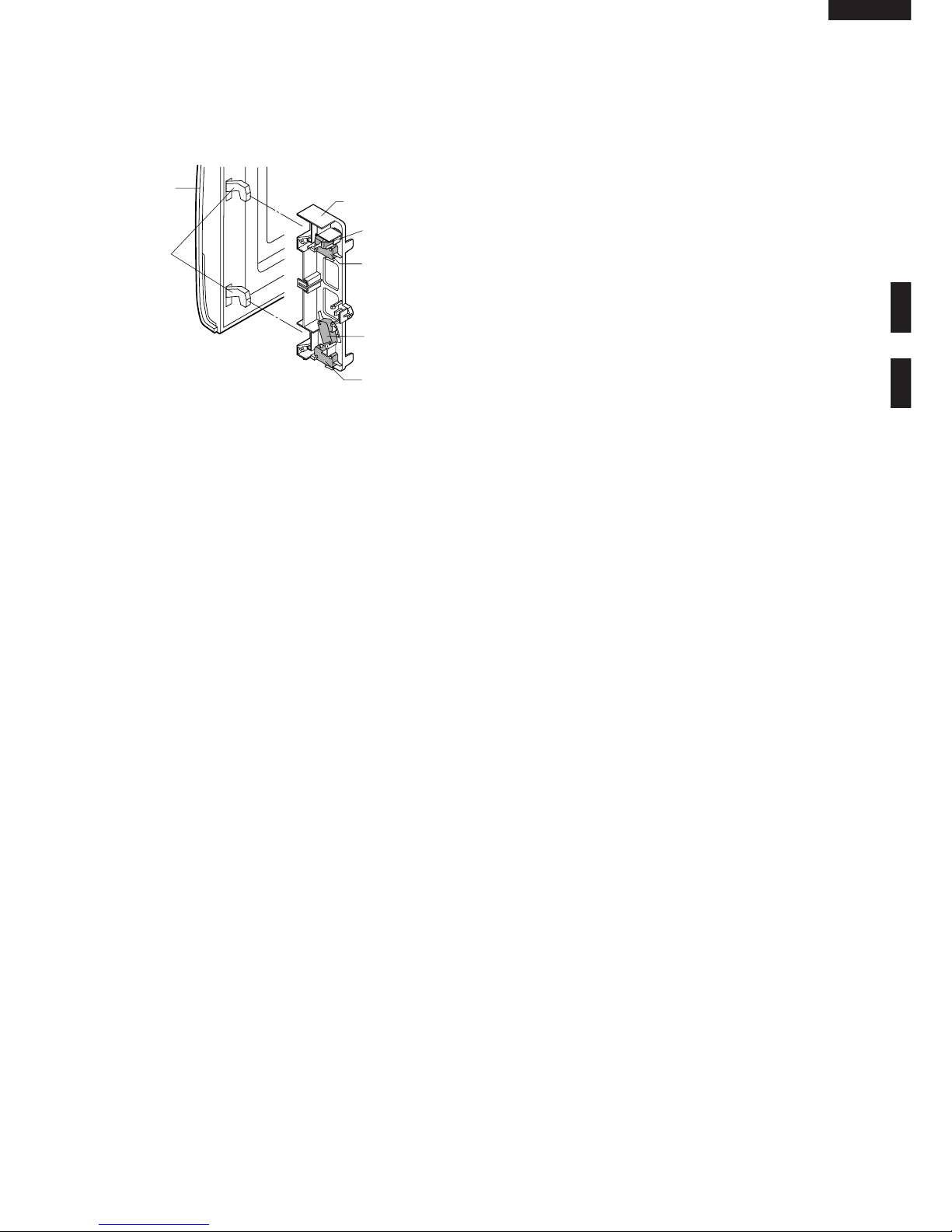
Closing the door activates all door interlock switches
(1st. latch switch, 2nd. latch switch and stop switch).
IMPORTANT
Whentheovendoorisclosed,themonitorswitchcontacts
(COM-NC) must be open.
Whenthemicrowaveovenispluggedinawalloutlet,rated
voltage is supplied to the noise filter and the control unit.
Figure O-1 on page 25
1. The display shows "SHARP MICRO-WAVE OVEN".
2. To set any programmes or set the clock, you must
first touch the STOP/CLEAR pad.
3. : appears in the display.
NOTE: When the oven door is opened, the oven lamp
comes on at this time.
MICROWAVE COOKING CONDITION
HIGH COOKING
Enter a desired cooking time with the touching NUMBER
pad and start the oven with touching START pad.
Function sequence
Figure O-2 on page 25
CONNECTED COMPONENTS RELAY
Oven lamp, Fan motor, Turntable motor RY1
Power transformer RY2
1. Ratedvoltage issupplied tothe primarywindingof the
power transformer. The voltage is converted to about
3.3 volts A.C. output on the filament winding and high
voltage of approximately 2000 volts A.C. on the
secondary winding.
2. The filament winding voltage (3.3 volts) heats the
magnetronfilamentandthehighvoltage(2000volts)is
sentto thevoltage doublingcircuit, whereit isdoubled
to negative voltage of approximately 4000 volts D.C..
3. The 2450 MHz microwave energy produced in the
magnetron generates a wave length of 12.24 cm. This
energyischanneledthroughthewaveguide(transport
channel)into theovencavity,where thefoodis placed
to be cooked.
4. Whenthecookingtimeisup,asignaltoneisheardand
the relays RY1+RY2 go back to their home position.
The circuits to the oven lamp, power transformer, fan
motor and turntable motor are cut off.
5. When the door is opened during a cook cycle, the
switches come to the following condition
CONDITION
DURING DOOR OPEN
SWITCH CONTACT COOKING
(NOCOOKING)
1st. latch switch COM-NO Closed Open
2nd. latch switch COM-NO Closed Open
Monitor switch COM-NC Open Closed
Stop switch COM-NO Closed Open
The circuits to the power transformer, fan motor and
turntable motor are cut off when the 1st. latch switch,
2nd.latchswitch,and stopswitcharemadeopen.The
ovenlamp remainson evenif theoven dooris opened
after the cooking cycle has been interrupted, because
therelayRY1staysclosed.Shown inthedisplayisthe
remaining time.
6. MONITOR SWITCH CIRCUIT
The monitor switch is mechanically controlled by
oven door, and monitors the operation of the 1st and
2nd. latch switches.
6-1 When the oven door is opened during or after the
cycleofacookingprogram,the1st.latchswitch,2nd.
latchswitchandstopswitchmustopen their contacts
first.
After that the contacts (COM-NC) of the monitor
switch can be closed.
6-2. When the oven door is closed, the contacts (COM-
NC) of the monitor switch must be opened. After that
thecontacts ofthe 1st.latch switch,2nd.latch switch
and stop switch are closed.
6-3. When the oven door is opened and the contacts of
the1st. latch switch, 2nd. latch switch remain closed.
ThefuseM10A willblow,becausethe monitorswitch
is closed and a short circuit is caused.
MEDIUM HIGH, MEDIUM, MEDIUM LOW, LOW
COOKING
When the microwave oven is preset for variable cooking
power, 230-240 volts A.C. power is supplied to the power
transformer intermittently within a 32-second time base
through the relay contact which is coupled with the cur-
rent-limitingrelay.Thefollowinglevelsofmicrowavepower
are given.
SETTING;
NOTE: TheON/OFFtimeratiodoesnotexactlycorrespond
to the percentage of microwave power, because
approx. 2 seconds are needed for heating up the
magnetron filament.
32 sec. ON
24 sec. ON
18 sec. ON
12 sec. ON
6 sec. ON
8 sec. OFF
14 sec. OFF
20 sec. OFF
26 sec. OFF
HIGH
MEDIUM HIGH
MEDIUM
MEDIUM LOW
LOW
Approx. 70%
Approx. 50%
Approx. 30%
Approx. 10%

R-350D
5
FUNCTION OF IMPORTANT COMPONENTS
OVEN THERMAL CUT-OUT
Thethermal cut-out,located onthetop ofthe ovencavity,
is designed to prevent damage to the oven by fire. If the
foods load is overcooked, by either error in cook time or
defect in the control unit, the thermal cut-out will open.
Undernormaloperation,theoventhermalcut-outremains
closed.However,whenabnormallyhightemperaturesare
reached within the oven cavity, the oven thermal cut-out
will open at 125˚C, causing the oven to shut down. The
defective thermal cut-out must be replaced with new one.
MAGNETRON THERMAL CUT-OUT
The thermal cut-out located near the magnetron is de-
signed to prevent damage to the magnetron if an over
heated condition develops in the tube due to cooling fan
failure,obstructedairguide,dirtyorblockedairintake,etc.
Under normal operation, the thermal cut-out remains
closed.However,whenabnormallyhightemperaturesare
reached within the magnetron, the thermal cut-out will
open at 95˚C causing the oven to shut down, when the
magnetronhascooledto 75˚C,thethermalcut-outcloses
and cook cycle will resume.
TURNTABLE MOTOR
Theturntablemotordrivestheturntablerollerassemblyto
rotate the turntable.
FAN MOTOR
Thefanmotordrivesabladewhichdrawsexternalcoolair.
Thiscool airisdirected throughthe air vanessurrounding
the magnetron and cools the magnetron. This air is
channeled through the oven cavity to remove steam and
vapors given off from the heating foods. It is then ex-
hausted through the exhausting air vents at the oven
cavity
NOISE FILTER
The noise filter prevents the radio frequency interference
that might flow back in the power circuit.
DOOR OPEN MECHANISM
Thedoor isopened bypulling thedoor,refer tothe Figure
D-1.
Figure D-1. Door Open Mechanism
1ST.LATCHSWITCH,2ND.LATCHSWITCHAND
STOP SWITCH
1. Whentheovendoorisclosed,thecontacts (COM-NO)
must be closed.
2. When the oven door is opened, the contacts (COM-
NO) must be opened.
MONITOR SWITCH
1. Whentheovendoorisclosed,thecontacts(COM-NC)
must be opened.
2. When the oven door is opened, the contacts (COM-
NC) must be closed.
3. Iftheovendoorisopenedandthecontacts(COM-NO)
ofthe1st.latchswitchand2nd.latchswitchfailtoopen,
the fuse M10A blows simultaneously with closing the
contacts (COM-NC) of the monitor switch.
CAUTION: BEFORE REPLACING A BLOWN FUSE
M10ATESTTHE1ST.LATCHSWITCH, 2ND.
LATCH SWITCH MONITOR SWITCH AND
MONITOR RESISTOR FOR PROPER OP-
ERATION.
MONITOR RESISTOR 0.8Ω20W
The monitor resistor prevents the fuse M10A bursting
when the fuse M10A blows due to the operation of the
monitor switch.
HIGH VOLTAGE FUSE
Thehighvoltagefuseblowswhenthehighvoltagerectifier
or magnetron is shorted.
FUSE M10A
1. ThefuseM10Ablowswhenthecontacts(COM-NO)of
the 1st. latch switch and 2nd. latch switch remain
closed with the oven door open and when the monitor
switch closes.
2. If the wire harness or electrical components are short-
circuited, this fuse M10A blows to prevent an electric
shock or fire hazard.
Latch Hook
Stop Switch
2nd. Latch
Switch
Latch
Heads
Door
Monitor Switch
1st. Latch
Switch

R-350D
6
SERVICING
WARNING TO SERVICE PERSONNEL
Microwaveovenscontaincircuitrycapableofproducingveryhighvoltageandcurrent,contactwithfollowingparts
of the high voltage circuit will result in electrocution. High voltage capacitor, Power transformer, Magnetron, High
voltage rectifier assembly, High voltage fuse, High voltage harness.
REMEMBER TO CHECK 3D
1) Disconnect the supply.
2) Door opened, and wedged open.
3) Discharge the high voltage capacitor.
WARNING: AGAINST THE CHARGE OF THE
HIGH-VOLTAGE CAPACITOR
Thehigh-voltagecapacitorremainschargedabout
60 seconds after the oven has been switched off.
Wait for 60 seconds and then short-circuit the
connectionofthehigh-voltagecapacitor(thatis,of
the connecting lead of the high-voltage rectifier)
against the chassis with the use of an insulated
screwdriver.
Sharprecommendthatwhereverpossiblefault-finding
is carried out with the supply disconnected. It may, in
some cases, be necessary to connect the supply after
the outer case has been removed, in this event carry
out 3D checks and then disconnect the leads to the
primary of the power transformer. Ensure that these
leads remain isolated from other components and the
ovenchassis.(Useinsulationtapeifnecessary.)When
the testing is completed carry out 3D checks and
reconnect the leads to the primary of the power trans-
former.
REMEMBER TO CHECK 4R
1) Reconnect all leads removed from components
during testing.
2) Replace the outer case (cabinet).
3) Reconnect the supply.
4) Run the oven. Check all functions.
Microwave ovensshould notbe runempty. Totest for
the presence of microwave energy within a cavity,
place a cup of cold water on the oven turntable, close
the door and set the microwave timer for two (2)
minutes. Set the power level to HIGH and push the
START button. When the two minutes has elapsed
(timeratzero)carefullycheckthatthewaterisnowhot.
If the water remains cold carry out 3D checks and re-
examine the connections to the component being
tested.
When troubleshooting the microwave oven, it is helpful to
follow the Sequence of Operation in performing the
checks.Manyofthepossiblecausesoftroublewillrequire
that a specific test be performed. These tests are given a
procedure letter which will be found in the "Test
Procedure"section.
When all service work is completed, and the oven is fully assembled, the microwave power output should be
checked and microwave leakage test should be carried out.
TROUBLESHOOTING GUIDE
IMPORTANT: If the oven becomes inoperative because
of a blown fuse M10A in the 1st. latch
switch - 2nd. latch switch - monitor switch
- monitor resistor circuit, check the 1st.
latch switch, 2nd. latch switch, monitor
switchand monitorresistorbeforereplac-
ing the fuse M10A.

R-350D
7
MAGNETRON
POWER TRANSFORMER
H.V. RECTIFIER ASSEMBLY
HIGH VOLTAGE CAPACITOR
1ST. LATCH SWITCH
2ND. LATCH SWITCH
STOP SWITCH
MONITOR SWITCH
MONITOR RESISTOR
THERMAL CUT-OUT 95˚C /125˚C
FAN MOTOR
TURNTABLE MOTOR
FUSE M10A
TOUCH CONTROL PANEL
KEY UNIT
RELAY (RY-1, RY-2)
FOIL PATERN ON P.W.B.
POWER SUPPLY CORD
SHORTED WIRE HARNESS
OPENED WIRE HARNESS
OVEN LAMP OR SOCKET
WALL OUTLET
MISADJUSTMENT SWITCH
HOME FUSE OR BREAKER
BLOCKED COOLING FAN
BLOCKED VENTILATION
NOISE FILTER
HIGH VOLTAGE FUSE
Homefuseblowswhenpower
supply cord is plugged into
wall outlet.
FUSE M10A blows when
power supply cord is plugged
into wall outlet.
Display does not show any-
thingwhenpowersupply cord
is plugged into wall outlet.
Display doesnotoperateprop-
erly when STOP/CLEAR pad
is touched.
Oven lamp does not light at
door opened. (Display ap-
pears.)
Oven does not start when the
START pad is touched. (Dis-
play appears)
Ovenlampdoesnotlight(Dis-
play appears.)
Fan motor does not operate.
(Display appears.)
Turntable motor assembly
does not operate. (Display
appears.)
Oven or any electrical parts
does not stop when cooking
timeis0orSTOP/CLEARpad
is touched.
Oven seems to be operating
butlittleornoheatisproduced
in oven load. (Microwave
power level is set at HIGH)
Oven does not seems to be
operating properly when ME-
DIUM HIGH, MEDIUM, ME-
DIUM LOW or LOW is set.
(Oven operates properly at
HIGH and then the STOP/
CLEAR pad is touched the
oven stops.)
Ovengoesintocookcyclebut
shutsdownbeforeendofcook-
ing cycle.
TEST PROCEDURE
CK = Check / RE = Replace
ABC
D
EEEEGFHHILMNO
RECK CK RE CK CK CKCK CK
JK
CONDITION PROBLEM
POSSIBLE CAUSE
AND
DEFECTIVE PARTS
ON
CONDITION
OFF
CONDITION

R-350D
8
TEST PROCEDURES
PROCEDURE
LETTER COMPONENT TEST
AMAGNETRON TEST
NEVER TOUCH ANY PART IN THE CIRCUIT WITH YOUR HAND OR AN INSULATED TOOL
WHILE THE OVEN IS IN OPERATION.
CARRY OUT 3D CHECK.
Isolatethe magnetronfrom high voltagecircuit byremovingall leadsconnected tofilamentterminal.
Totestforanopencircuitfilamentuseanohmmetertomakeacontinuitytestbetweenthemagnetron
filament terminals, the meter should show a reading of less than 1 ohm.
To test for short circuit filament to anode condition, connect ohmmeter between one of the filament
terminalsandthecaseofthemagnetron(ground).Thistestshouldbeindicatedaninfiniteresistance.
If a low or zero resistance reading is obtained then the magnetron should be replaced.
MICROWAVE OUTPUT POWER (1 litre water load)
The following test procedure should be carried out with the microwave oven in a fully assembled
condition (outer case fitted). Microwave output power from the magnetron can be measured by IEC
testprocedure,i.e.itcanbemeasuredbyusingwaterloadhowmuchitcanbeabsorbedbythewater
load.Tomeasurethemicrowaveoutputpowerinthemicrowaveoven,therelationofcalorieandwatt
is used. When P(W) heating works for t(second), approximately P x t/4.187 calorie is generated. On
theotherhand, if thetemperatureofthe water withV(ml)rises∆T(˚C)during thismicrowaveheating
period, the calorie of the water is V x ∆T.
The formula is as follows;
P x t / 4.187 = V x ∆T+ 0.55 x mc (T2-T0)
P
(W) = 4.187 x V x ∆T / t + 0.55 x mc (T2-T0)/t
Our condition for water load is as follows:
Room temperature (T0) ... around 20°C Power supply Voltage..............Rated voltage
Water load..................................1000 g Initial temperature (T1) ...................... 10±1°C
Heating time.............................. 38 sec. Mass of container (mc) ......................... 330 g
T2............................ Final Temperature P = 110 x ∆T + 0.55 x mc (T2-T0)/38
Measuring condition:
1. Container
The water container must be a cylindrical borosilicate glass vessel having a maximum material
thickness of 3 mm and an outside diameter of approximately 190 mm.
2. Temperature of the oven and vessel
The oven and the empty vessel are at ambient temperature prior to the start of the test.
3. Temperature of the water
The initial temperature of the water is (10±1)˚C.
4. Select the initial and final water temperature so that the maximum difference between the final
water temperature and the ambient temperature is 5˚C.
5. Selectstirringdevicesandmeasuringinstrumentsinordertominimizeadditionorremovalofheat.
6. The graduation of the thermometer must be scaled by 0.1˚C at minimum and an accurate
thermometer.
7. The water load must be (1000±5) g.
8. “t”ismeasuredwhilethemicrowavegeneratorisoperatingatfullpower.Magnetronfilamentheat-
up time is not included.
NOTE: The operation time of the microwave oven is “t + 2” sec. 2 sec. is magnetron filament heat-
up time.
Measuring method:
1. Measure the initial temperature of the water before the water is added to the vessel.
(Example: The initial temperature T1 = 11˚C)
2. Add the 1 litre water to the vessel.
3. Place the load on the centre of the shelf.
4. Operate the microwave oven at HIGH for the temperature of the water rises by a value ∆T of
(10 ±2)˚C.
5. Stir the water to equalize temperature throughout the vessel.
6. Measure the final water temperature. (Example: The final temperature T2 = 21°C)
7. Calculate the microwave power output P in watts from above formula.

R-350D
9
Room temperature .................. To = 21˚C Initial temperature................. T1 = 11°C
Temperature after (38 + 2) = 40 sec. ................................................................ T2 = 21°C
Temperature difference Cold-Warm .............................................................. ∆T1 = 10°C
Measured output power
The equation is “P = 110 x ∆T” ........................................... P = 110 x 10°C = 1100 Watts
TEST PROCEDURES
PROCEDURE
LETTER COMPONENT TEST
1000g
1000g
1000g
T1˚C T2˚C
Heat up for 40 sec.
BPOWER TRANSFORMER TEST
WARNING: Highvoltagesandlargecurrentsarepresentatthesecondarywindingandfilament
winding of the power transformer. It is very dangerous to work near this part when
the oven is on. NEVER make any voltage measurements of the high-voltage
circuits, including the magnetron filament.
CARRY OUT 3D CHECKS.
Disconnect the leads to the primary winding of the power transformer. Disconnect the filament and
secondary winding connections from the rest of the HV circuitry. Using an ohmmeter, set on a low
range, it is possible to check the continuity of all three windings. The following readings should be
obtained:
a. Primary winding ....................approx. 1.0 Ω
b. Secondary winding ...............approx. 87 Ω
c. Filament winding...................less than 1Ω
If the reading obtained are not stated as above, then the power transformer is probably faulty and
should be replaced.
CARRY OUT 4R CHECKS.
CHIGH VOLTAGE RECTIFIER ASSEMBLY TEST
HIGH VOLTAGE RECTIFIER TEST
CARRY OUT 3D CHECKS.
IsolatethehighvoltagerectifierassemblyfromtheHVcircuit.Thehighvoltagerectifier canbetested
using an ohmmeter set to its highest range. Connect the ohmmeter across the terminal B+C of the
high voltage rectifier and note the reading obtained. Reverse the meter leads and note this second
reading.Thenormalresistanceisinfiniteinonedirectionandmorethan100kΩintheotherdirection.
CARRY OUT 4R CHECKS.
NOTE: FOR MEASUREMENT OF THE RESISTANCE OF THE RECTIFIER, THE BATTERIES OF
THEMEASURINGINSTRUMENTMUSTHAVEAVOLTAGEATLEAST6VOLTS,BECAUSE
OTHERWISE AN INFINITE RESISTANCE MIGHT BE SHOWN IN BOTH DIRECTIONS.
BC
HIGH VOLTAGE RECTIFIER
JUDGMENT: The measured output power should be at least ±15 % of the rated output power.
CAUTION: 1°C CORRESPONDS TO 110 WATTS REPEAT MEASUREMENT IF THE POWER IS
INSUFFICIENT.

R-350D
10
CARRY OUT 3D CHECKS.
Disconnect the leads from the monitor resistor. Using an ohmmeter and set on a low range. Check
between the terminals of the monitor resistor.
The resistance of monitor resistor is approx. 0.8 ohms.
GMONITOR RESISTOR TEST
TEST PROCEDURES
PROCEDURE
LETTER COMPONENT TEST
D HIGH VOLTAGE CAPACITOR TEST
CARRY OUT 3D CHECKS.
A. Isolate the high voltage capacitor from the circuit.
B. Continuity check must be carried out with measuring instrument which is set to the highest
resistance range.
C. A normal capacitor shows continuity for a short time (kick) and then a resistance of about 10MΩ
after it has been charged.
D. A short-circuited capacitor shows continuity all the time.
E. An open capacitor constantly shows a resistance about 10 MΩbecause of its internal 10MΩ
resistance.
F. When the internal wire is opened in the high voltage capacitor shows an infinite resistance.
G. The resistance across all the terminals and the chassis must be infinite when the capacitor is
normal.
If incorrect reading are obtained, the high voltage capacitor must be replaced.
CARRY OUT 4R CHECKS.
ESWITCH TEST
CARRY OUT 3D CHECKS.
Isolate the switch to be tested and using an ohmmeter check between the terminals as described in
the following table.
Table: Terminal Connection of Switch
Plunger Operation COM to NO COM to NC COM; Common terminal
Released Open circuit Short circuit NO; Normally open terminal
Depressed Short circuit Open circuit NC; Normally close terminal
If incorrect readings are obtained, make the necessary switch adjustment or replace the switch.
CARRY OUT 4R CHECKS.
CARRY OUT 3D CHECKS.
Disconnect the leads from the terminals of the temperature fuse or thermal cut-out. Then using an
ohmmeter, make a continuity test across the two terminals as described in the table below.
CARRY OUT 4R CHECKS.
Table: Temperature fuse and Thermal cut-out Test
Temperature of "ON" condition Temperature of "OFF" condition Indication ofohmmeter
Parts Name (closed circuit) (˚C) (open circuit) (˚C) (When room temperature
is approx. 20˚C)
Thermal cut-out 125˚C This is not resetable type. Above 125˚C Closed circuit.
Thermal cut-out 95˚C Below 75˚C Above 95˚C Closed circuit.
If incorrect readings are obtained, replace the temperature fuse or thermal cut-out.
Anopencircuitthermal cut-out95˚C(MG)indicatesthatthe magnetronhasoverheated,thismay be
duetoresistrictedventilation,coolingfanfailureorafaultconditionwithinthemagnetronorHVcircuit.
An open circuit thermal cut-out 125˚C (OVEN) indicates that the foods in the oven may catch fire,
this may be due to over heating produced by improper setting of the cooking time or failure of the
control panel.
F TEMPERATURE FUSE AND THERMAL CUT-OUT TEST

R-350D
11
TEST PROCEDURES
PROCEDURE
LETTER COMPONENT TEST
CARRY OUT 3D CHECKS.
Disconnect the leads from the motor.
Usinganohmmeter,checktheresistancebetweenthetwoterminalsasdescribedinthetablebelow.
Table: Resistance of Motor
Motors Resistance
Fan motor Approximately 390 Ω
Turntable motor Approximately 12 kΩ
If incorrect readings are obtained, replace the motor.
CARRY OUT 4R CHECKS
HMOTOR WINDING TEST
CARRY OUT 3D CHECKS.
1. If the fuse M10A is blown, there could be shorts or ground in electrical parts or wire harness.
Check them and replace the defective parts or repair the wire harness.
2. If the fuse M10A is blown when the door is opened, check the 1st. latch switch, 2nd. latch switch,
monitor switch and monitor resistor.
Ifthe fuseM10A isblownby incorrectdoor switchingreplace the defectiveswitch(s) andthe fuse
M10A.
CARRY OUT 4R CHECKS.
CAUTION: ONLY REPLACE FUSE M10A WITH THE CORRECT VALUE REPLACEMENT
IBLOWN FUSE M10A
JNOISE FILTER TEST
CARRY OUT 3D CHECKS.
Disconnect the leads from the terminals of the noise
filter. Using an ohmmeter, check between the termi-
nals as described in the following table.
MEASURING POINT INDICATION OF
OHMMETER
Between N and L Open circuit
Between terminal N and WHITE Short circuit
Between terminal L and RED Short circuit
If incorrect readings are obtained, replace the noise filter unit.
CARRY OUT 4R CHECKS.
N
LCx L
L
Cy
WHT
RED
L (min) Cx ±20% Cy ±20%
600µH 0.068µF 0.0022µF
CARRY OUT 3D CHECKS.
Ifthehighvoltagefuse isblown,therecouldbeashortin the highvoltage rectifierorthemagnetron.
Check them and replace the defective parts and high voltage fuse.
CARRY OUT 4R CHECKS.
CAUTION: ONLY REPLACE THE HIGH VOLTAGE FUSE WITH THE CORRECT VALUE RE-
PLACEMENT
K HIGH VOLTAGE FUSE TEST
If incorrect readings are obtained, replace the monitor resistor.
CARRY OUT 4R CHECKS.

R-350D
12
TEST PROCEDURES
PROCEDURE
LETTER COMPONENT TEST
M KEY UNIT TEST
If the display fails to clear when the STOP/CLEAR pad is depressed, first verify the flat ribbon cable
ismakinggoodcontact,verifythatthedoorsensingswitch(stopswitch)operatesproperly;thatisthe
contacts are closed when the door is closed and open when the door is open.
Ifthedoorsensingswitch(stopswitch)isgood,disconnecttheflatribboncablethatconnectsthekey
unittothecontrolunit andmakesurethedoorsensingswitchis closed(eitherclosethedoororshort
thedoorsensing switch connector).Usethekey unit matrixindicatedonthecontrol panelschematic
and place a jumper wire between the pins that correspond to the STOP/CLEAR pad making
momentarycontact.Ifthecontrolunitrespondsbyclearingwithabeepthekeyunitisfaultyandmust
be replaced. If the control unit does not respond, it is faulty and must be replaced.
If a specific pad does not respond, the above method may be used (after clearing the control unit) to
determine if the control unit or key pad is at fault.
CARRY OUT 3D CHECKS.
L TOUCH CONTROL PANEL ASSEMBLY TEST
ThetouchcontrolpanelconsistsofcircuitsincludingsemiconductorssuchasLSI,ICs,etc.Therefore,
unlike conventional microwave ovens, proper maintenance cannot be performed with only a
voltmeterandohmmeter.Inthisservicemanual,thetouchcontrolpanelassemblyisdivided intotwo
units, Control Unit and Key Unit, and also the Control Unit is divided into two units, CPU Unit and
Power Unit, and troubleshooting by unit replacement is described according to the symptoms
indicated.
1. Key Unit. Note: Check key unit ribbon connection before replacement.
The following symptoms indicate a defective key unit. Replace the key unit.
a) When touching the pads, a certain pad produces no signal at all.
b) When touching a number pad, two figures or more are displayed.
c) When touching the pads, sometimes a pad produces no signal.
2. Control Unit.
Thefollowingsymptomsindicateadefectivecontrolunit.Beforereplacingthecontrolunit,perform
the Key unit test (Procedure M) to determine if control unit is faulty.
2-1 In connection with pads.
a) When touching the pads, a certain group of pads do not produce a signal.
b) When touching the pads, no pads produce a signal.
2-2 In connection with indicators.
a) At a certain digit, all or some segments do not light up.
b) At a certain digit, brightness is low.
c) Only one indicator does not light.
d) The corresponding segments of all digits do not light up; or they continue to light up.
e) Wrong figure appears.
f) A certain group of indicators do not light up.
g) The figure of all digits flicker.
2-3 Other possible troubles caused by defective control unit.
a) Buzzer does not sound or continues to sound.
b) Clock does not operate properly.
c) Cooking is not possible.
54321
09876
BEVERAGE
POWER
LEVEL
FROZEN
DINNER
MEAT CLOCK TIMER
HELP
LESS
DINNER
PLATE
RICE/
PASTA
PASTA
MEAL
EASY
DEFROST
EXPRESS
DEFROST
STOP
CLEAR
VEGETABLES
INSTANT
COOK
START
G 8
G 9
G10
G11
G12
G13
G14
G 7 G 6 G 5 G 4 G 3 G 2 G 1
SOUP
CASSEROLE
PIE PIZZA
MORE

R-350D
13
To protect the electronic circuits, this model is provided with a fine foil pattern added to the primary
onthePWB,thisfoil patternactsasafuse.Ifthefoil patternisopen,followthetroubleshootingguide
given below for repair.
Problem: POWER ON, indicator does not light up.
CARRY OUT 3D CHECKS.
STEPS OCCURRENCE CAUSE OR CORRECTION
The rated AC voltage is not present between
1 Pin No. 1 of the 2-pin connector (A) and the Check supply voltage and oven power cord.
normal open terminal of the relay RY1.
2The rated AC voltage is present to primary Low voltage transformer or secondary circuit defective.
side of low voltage transformer. Check and repair.
3 Only pattern at "a" is broken. *Insert jumper wire J1 and solder.
4 Pattern at "a" and "b" are broken. *Insert the coil RCILF2003YAZZ between "c" and "d".
NOTE: *At the time of making these repairs,
makeavisualinspectionofthevaristor.
Checkfor burned damageand exam-
inethetransformerwithatesterforthe
presence of layer short-circuit (check
the primary coil resistance). If any ab-
normal condition is detected, replace
the defective parts.
CARRY OUT 4R CHECKS.
TEST PROCEDURES
PROCEDURE
LETTER COMPONENT TEST
NRELAY TEST
OPROCEDURES TO BE TAKEN WHEN THE FOIL PATTERN ON THE PRINTED WIRING BOARD
(PWB) IS OPEN
RemovetheoutercaseandcheckvoltagebetweenPinNo1ofthe2-pinconnector(A)andthenormal
open terminal of the relay RY1 on the power unit with an A.C. voltmeter. The meter should indicate
230 - 240 volts, if not check oven circuit.
RY1 and RY2 Relay Test
These relays are operated by D.C. voltage.
Check voltage at the relay coil with a D.C. voltmeter during the microwave cooking operation.
DC. voltage indicated............... Defective relay.
DC. voltage not indicated ......... Checkdiodewhichisconnectedtotherelaycoil.Ifdiodeisgood,
control unit is defective.
RELAY SYMBOL OPERATIONAL VOLTAGE CONNECTED COMPONENTS
RY1 APPROX. 24.0V D.C. Oven lamp / Turntable motor / Cooling fan motor
RY2 APPROX. 23.0V D.C. Power transformer
CARRY OUT 4R CHECKS.
RY1
VRS1
T1
RY3
(J1)
a
b
cd

R-350D
14
TOUCH CONTROL PANEL ASSEMBLY
OUTLINE OF TOUCH CONTROL PANEL
The touch control section consists of the following units.
(1) Key Unit
(2) Control Unit (TheControl UnitconsistsofPowerUnit
and LSI Unit).
The principal functions of these units and the signals
communicated among them are explained below.
Key Unit
The key unit is composed of a matrix, signals generated
in the LSI are sent to the key unit through P10-P17.
Whenakeypadistouched,asignaliscompletedthrough
the key unit and passed back to the LSI through AN11,
AN10, AN9, P42, P41 and AN8 to perform the function
that was requested.
Control Unit
Control unit consists of LSI, ACL circuit, indicator circuit,
powersourcecircuit,relaycircuit,buzzercircuit,synchro-
nizing signal circuit and back light circuit.
1) ACL
This circuit generates a signal which resets the LSI to
the initial state when power is supplied.
2) Indicator Circuit
This circuit consists of 40 segments and 16 common
electrodes using a Liquid Crystal Display.
The Liquid Crystal Display (LCD) is drived by LCD
driver IC3.
3) Power Source Circuit
Thiscircuitgeneratesvoltagesnecessaryinthecontrol
unit from the AC line voltage.
In addition, the synchronizing signal is available in
order to compose a basic standard time in the clock
circuit.
Symbol Voltage Application
VC -5V LSI(IC1)
4) Relay Circuit
A circuit to drive the magnetron, fan motor, turntable
motor and light the oven lamp.
5) Buzzer Circuit
ThebuzzerisresponsivetosignalsfromtheLSItoemit
audible sounds (key touch sound and completion
sound).
6) Synchronizing Signal Circuit
The power source synchronizing signal is available in
order to compose a basic standard time in the clock
circuit.
It accompanies a very small error because it works on
commercial frequency.
7) Door Sensing Switch
A switch to “tell” the LSI if the door is open or closed.
8) Back Light Circuit
A circuit to drive the back light (Light emitting diodes
LD10-LD19).

R-350D
15
1 AN10 IN Signal coming from touch key.
When either G10 line on key matrix is touched, a corresponding signal out of P10 - P17
will be input into AN10. When no key is touched, the signal is held at "H" level.
2 AN11 IN Signal similar to AN10.
When either G9 line on key matrix is touched, a corresponding signal will be input into
AN11.
3 AVSS IN Connected to VC.
4 P10 OUT Key strobe signal.
Signalapplied totouch-keysection.A pulsesignalis inputtoAN9, AN10,AN11,P41and
P42 terminal while one of G8 line keys on key matrix is touched.
5 P11 OUT Key strobe signal.
Signalappliedtotouch-keysection.ApulsesignalisinputtoAN8,AN9,AN10,AN11,P41
and P42 terminal while one of G7 line keys on key matrix is touched.
6 P12 OUT Key strobe signal.
Signalapplied totouch-keysection.A pulsesignalis inputtoAN9, AN10,AN11,P41and
P42 terminal while one of G6 line keys on key matrix is touched.
7 P13 OUT Key strobe signal.
Signalapplied totouch-keysection.A pulsesignalis inputtoAN9, AN10,AN11,P41and
P42 terminal while one of G5 line keys on key matrix is touched.
8 P14 OUT Key strobe signal.
Signalapplied totouch-keysection.A pulsesignalis inputtoAN9, AN10,AN11,P41and
P42 terminal while one of G4 line keys on key matrix is touched.
9 P15 OUT Key strobe signal.
Signalapplied totouch-keysection.A pulsesignalis inputtoAN9, AN10,AN11,P41and
P42 terminal while one of G3 line keys on key matrix is touched.
10 P16 OUT Key strobe signal.
Signalapplied totouch-keysection.A pulsesignalis inputtoAN9, AN10,AN11,P41and
P42 terminal while one of G2 line keys on key matrix is touched.
11 P17 OUT Key strobe signal.
Signalapplied totouch-keysection.A pulsesignalis inputtoAN9, AN10,AN11,P41and
P42 terminal while one of G1 line keys on key matrix is touched.
12 X1 IN Connected to GND.
13 X2 OUT Terminal not used.
14 VSS IN Power source voltage: -5.0V.
VC voltage of power source circuit input.
15 OSC2 OUT Internal clock oscillation frequency control output.
Output to control oscillation input of OSC2.
16 OSC1 IN Internal clock oscillation frequency input setting.
The internal clock frequency is set by inserting the ceramic filter oscillation circuit with
respect to OSC1 terminal.
17 TEST IN Connected to VC.
18 RES IN Auto clear terminal.
Signal is input to reset the LSI to the initial state when power is applied. Temporarily set
"L" level the moment power is applied, at this time the LSI is reset. Thereafter set at "H"
level.
19 P20 OUT Signal to sound buzzer (2.0 kHz).
A: key touch sound.
B: Completion sound.
20 P21 OUT Terminal not used.
21 P22
IN/OUT
Terminal not used.
22 P23 OUT Terminal not used.
LSI(IXA049DR)
The I/O signal of the LSI(IXA049DR) is detailed in the following table.
Pin No. Signal I/O Description
A
B
0.12 sec.
2.4 sec.
H : GND
L : -5V
H : GND
L : -5V

R-350D
16
23 P24 OUT Oven lamp, fan motor and turntable motor driving signal
Toturnonandoffshutoffrelay(RY1).Thesquare
waveform voltage is delivered to the RY1 driving
circuit and RY2 control circuit.
24 P25 OUT Magnetron high-voltage circuit driving signal.
To turn on and off the cook relay (RY2). The
signals holds "L" level during microwave cooking
and "H" level while not cooking. In other cooking
modes (variable cooking) the signal turns to "H"
level and "L" level in repetition according to the
power level.
(ON and OFF times for other power level.)
25-26 P26-P27 OUT Terminal not used.
27-34 P30-P37 OUT Terminal not used.
35 CVCC IN Connected to GND.
36 VSS IN Power source voltage: -5.0V.
The power source voltage to the LSI is input to VSS terminal. Connected to VC.
37-38 V3-V2 IN Terminal not used.
39-40 V1-V0 IN Power source voltage input terminal.
Standard voltage for LCD. Connected to GND.
41 VCC IN Power source voltage: GND (0V).
The power source voltage to drive the LSI is input to VCC terminal.
42-45
COM4-COM1
OUT Terminal not used.
46-65
SEG1-SEG20
OUT Terminal not used.
66-79 P74-P91 OUT Data output terminal to LCD driver IC3.
80-85
SEG35-SEG40
OUT Terminal not used.
86 P40 OUT Terminal not used.
87 P41 IN Signal similar to AN10.
When either G13 line on key matrix is touched, a corresponding signal will be input into
P41.
88 P42 IN Signal similar to AN10.
When either G12 line on key matrix is touched, a corresponding signal will be input into
P42.
89 IRQ0 IN Signal synchronized with commercial power source frequency.
This is the basic timing for time processing of LSI.
90 AVCC IN A/D converter power source voltage.
The power source voltage to drive the A/D converter in the LSI. Connected to GND.
91-92 AN0-AN1 IN Connected to GND through resistor.
93 AN2 IN To input signal which communicates the door open/close information to LSI.
Door close "H" level signal (0V). Door open "L" level signal (-5V).
94 AN3 IN Connected to VC through resistor.
95-98 AN4-AN7 IN Terminal to change cooking input according to the Model.
ByusingtheA/DconvertercontainedintheLSI,DCvoltageinaccordancewiththeModel
in operation is applied to set up its cooking constant.
99 AN8 IN Input terminal to judge the model.
ThesignaloutofP11willbeinputintoAN8throughG7lineonkeymatrix.TheLSIwilljudge
the model by this signal.
100 AN9 IN Signal similar to AN10.
When either G11 line on key matrix is touched, a corresponding signal will be input into
AN9.
Pin No. Signal I/O Description
20.0 msec.
During cooking
H : GND
L : -5V
P-HI
H : GND
L : -5V
H : GND
L : -5V
P-70
ON
ON
OFF
OFF OFF
24 sec.
8 sec.
20.0 msec.
H : GND
L : -5V

R-350D
17
1. Precautions for Handling Electronic Components
This unit uses CMOS LSI in the integral part of the
circuits. When handling these parts, the following
precautions should be strictly followed. CMOS LSI
haveextremelyhigh impedanceatits input andoutput
terminals.For thisreason,it iseasilyinfluenced by the
surroundinghighvoltagepowersource,staticelectricity
charge in clothes, etc. and sometimes it is not fully
protected by the built-in protection circuit.
In order to protect CMOS LSI.
1) When storing and transporting, thoroughly wrap them
in aluminium foil. Also wrap all PW boards containing
them in aluminium foil.
2) Whensoldering,groundthetechnicianasshowninthe
figureandusegroundedsolderingironandworktable.
2. Shapes of Electronic Components
3. Servicing of Touch Control Panel
We describe the procedures to permit servicing of the
touch control panel of the microwave oven and the
precautions you must take when doing so. To perform
the servicing, power to the touch control panel is
availableeitherfromthepowerlineoftheovenitselfor
from an external power source.
(1) Servicingthetouchcontrolpanelwithpowersupply
of the oven:
CAUTION:
THE HIGH VOLTAGE TRANSFORMER OF THE
MICROWAVE OVEN IS STILL LIVE DURING
SERVICING PRESENTS A HAZARD.
Therefore, when checking the performance of the
touch control panel, put the outer cabinet on the oven
to avoid touching the high voltage transformer, or
unplug the primary terminal (connector) of the high
voltage transformer to turn it off; the end of such
connector must be insulated with an insulating tape.
After servicing, be sure to replace the leads to their
original locations.
A. On some models, the power supply cord between the
touch control panel and the oven itself is so short that
the two can’t be separated.
For those models, check and repair all the controls
(sensor-related ones included) of the touch control
panel while keeping it connected to the oven.
B. On some models, the power supply cord between the
touchcontrolpanelandtheovenproperislongenough
thattheymaybeseparatedfromeachother.Forthose
models,therefore,itispossibletocheckandrepairthe
controls of the touch control panel while keeping it
TOUCH CONTROL PANEL SERVICING
apartfromtheovenproper;inthiscaseyoumustshort
both ends of the door sensing switch (on PWB) of the
touch control panel with a jumper, which brings about
anoperationalstatethatisequivalenttotheovendoor
being closed. As for the sensor-related controls of the
touchcontrolpanel,checkingthemispossibleifdummy
resistor(s) with resistance equal to that of the controls
are used.
(2) Servicingthetouchcontrolpanelwithpowersupply
from an external power source:
Disconnect the touch control panel completely from
the oven proper, and short both ends of the door
sensing switch (on PWB) of the touch control panel,
which brings about an operational state that is
equivalent to the oven door being closed. Connect an
external power source to the power input terminal of
thetouchcontrolpanel,thenitispossibletocheckand
repair the controls of the touch control panel it is also
possible to check the sensor-related controls of the
touch control panel by using the dummy resistor(s).
4. Servicing Tools
Tools required to service the touch control panel
assembly.
1) Soldering iron: 30W
(It is recommended to use a soldering iron with a
grounding terminal.)
2) Oscilloscope: Single beam, frequency range: DC-
10MHz type or more advanced model.
3) Others: Hand tools
5. Other Precautions
1) Beforeturning onthe powersource ofthe controlunit,
removethealuminiumfoilappliedforpreventingstatic
electricity.
2) Connect the connectors of the key unit to the control
unit being sure that the lead wires are not twisted.
3) Afteraluminiumfoilisremoved,becarefulthatabnormal
voltageduetostaticelectricityetc.isnotappliedtothe
input or output terminals.
4)Attachconnectors,electrolyticcapacitors,etc.toPWB,
making sure that all connections are tight.
5) Be sure to use specified components where high
precision is required.
approx. 1M ohm
ECB
ECB
Transistor
2SB1238 Transistor
KRC243M

R-350D
18
HIGH VOLTAGE RECTIFIER, HIGH VOLTAGE FUSE AND HIGH VOLTAGE CAPACITOR REMOVAL
COMPONENT REPLACEMENT AND ADJUSTMENT PROCEDURE
WARNING: Avoid possible exposure to microwave energy. Please follow the instructions below before
operating the oven.
1. Disconnect oven from power supply.
2. Visuallycheckthedoorandcavityfaceplatefordamage
(dents, cracks, signs of arcing etc.).
Carry out any remedial work that is necessary before
operating the oven.
Do not operate the oven if any of the following conditions
exist;
1. Door does not close firmly.
2. Door hinge, support or latch hook is damaged.
3. The door gasket or seal or damaged.
4. The door is bent or warped.
5. There are defective parts in the door interlock system.
6. Therearedefective partsinthemicrowavegenerating
and transmission assembly.
7. There is visible damage to the oven.
Do not operate the oven:
1. Without the RF gasket (Magnetron).
2. If the wave guide or oven cavity are not intact.
3. If the door is not closed.
4. If the outer case (cabinet) is not fitted.
Please refer to ‘OVEN PARTS, CABINET PARTS, CONTROL PANEL PARTS, DOOR PARTS’, when carrying out any
of the following removal procedures:
WARNING FOR WIRING
To prevent an electric shock, take the following
manners.
1. Before wiring,
1) Disconnect the power supply.
2) Open the door and wedge the door open.
3) Dischargethehighvoltagecapacitorandwaitfor
60 seconds.
2. Don't let the wire leads touch to the following parts;
1) High voltage parts:
Magnetron, High voltage transformer, High
voltagecapacitor,Highvoltagerectifierassembly
and High voltage fuse.
2) Hot parts:
Ovenlamp,Magnetron,Highvoltagetransformer
and Oven cavity.
3) Sharp edge:
Bottom plate, Oven cavity, Waveguide flange,
Chassis support and other metallic plate.
4) Movable parts (to prevent a fault)
Fan blade, Fan motor, Switch, Open button.
3. Donotcatchthewireleadsintheoutercasecabinet.
4. Insert the positive lock connector certainly until its
pin is locked. And make sure that the wire leads
should not come off even if the wire leads is pulled.
5. To prevent an error function, connect the wire leads
correctly, referring to the Pictorial Diagram.
Re-install
1. Rest transformer on the bottom plate with its primary
terminals toward the oven face plate.
2. Secure transformer with four screws to bottom plate.
3. Re-connect wire leads (primary and high voltage) to
powertransformerandfilamentleadsoftransformerto
magnetron and high voltage capacitor. Refer to
"PICTORIAL DIAGRAM".
4. Re-install outer case and check that oven is operating
properly.
OUTER CASE REMOVAL
To remove the components, procedure as follows.
1. Disconnect oven from power supply.
2. Remove four(4) screws from rear and one (1) screw
along the right side edge of case.
3. Slidetheentirecasebackoutabout1inch(3cm)tofree
1. CARRY OUT 3D CHECKS.
2. Disconnectwire leads(primaryand highvoltage) from
power transformer.
3. Disconnectfilamentleadsfromthemagnetronandthe
high voltage capacitor.
4. Removefour(4) screws holdingtransformertobottom
plate.
5. Remove transformer from bottom plate.
POWER TRANSFORMER REMOVAL
it from retaining clips on the cavity face plate.
4. Lift entire case from the unit.
CAUTION: DISCONNECT OVEN FROM POWER SUP-
PLY BEFORE REMOVING OUTER CASE.
1. CARRY OUT 3D CHECKS.
2. Disconnect the brown and blue wires of power supply cord from the noise filter.
3. Disconnect the wire leads of the main wire harness
Other manuals for R-350D
1
Table of contents
Other Sharp Microwave Oven manuals

Sharp
Sharp R-2120J Use and care manual

Sharp
Sharp KB-6014LS User manual

Sharp
Sharp R-408JK User manual

Sharp
Sharp R-870B User manual

Sharp
Sharp R-9200 User manual

Sharp
Sharp R-522E User manual

Sharp
Sharp R-3E52 User manual

Sharp
Sharp R-1610 Use and care manual

Sharp
Sharp R-320DK User manual

Sharp
Sharp R-334 User manual

Sharp
Sharp YC-GC52B User manual

Sharp
Sharp R-21J User manual

Sharp
Sharp EBR-4810 User manual

Sharp
Sharp Microwave Drawer SMD3070ASY User manual

Sharp
Sharp R-953M User manual

Sharp
Sharp R-330EK User manual

Sharp
Sharp Carousel II R-1820 User manual

Sharp
Sharp R-202EK User manual

Sharp
Sharp R-26STM Instruction Manual

Sharp
Sharp R-410FW User manual