manuals.online logo
Brands
  1. Home
  2. •
  3. Brands
  4. •
  5. Sharp
  6. •
  7. Microwave Oven
  8. •
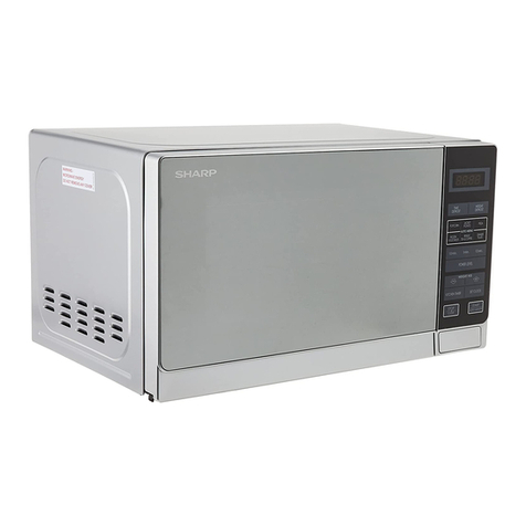
  9. Sharp R-THY11 User manual

Sharp R-THY11 User manual

This manual suits for next models

2

Other Sharp Microwave Oven manuals

Sharp Carousel R-1200 Specification sheet

Sharp

Sharp Carousel R-1200 Specification sheet

Sharp R-390F Use and care manual

Sharp

Sharp R-390F Use and care manual

Sharp R-520KS User manual

Sharp

Sharp R-520KS User manual

Sharp Carousel R-307E User manual

Sharp

Sharp Carousel R-307E User manual

Sharp R-952M User manual

Sharp

Sharp R-952M User manual

Sharp R-22AT User manual

Sharp

Sharp R-22AT User manual

Sharp R-404FK User manual

Sharp

Sharp R-404FK User manual

Sharp R-269 User manual

Sharp

Sharp R-269 User manual

Sharp Carousel R-140D User manual

Sharp

Sharp Carousel R-140D User manual

Sharp Carousel R-880B User manual

Sharp

Sharp Carousel R-880B User manual

Sharp R-90GCK User manual

Sharp

Sharp R-90GCK User manual

Sharp R-397F User manual

Sharp

Sharp R-397F User manual

Sharp Carousel R-1512 User manual

Sharp

Sharp Carousel R-1512 User manual

Sharp R-67STM Instruction Manual

Sharp

Sharp R-67STM Instruction Manual

Sharp Carousel R-380ZW User manual

Sharp

Sharp Carousel R-380ZW User manual

Sharp YC-PS204AU User manual

Sharp

Sharp YC-PS204AU User manual

Sharp R-633 Instruction Manual

Sharp

Sharp R-633 Instruction Manual

Sharp R-772M Instruction Manual

Sharp

Sharp R-772M Instruction Manual

Sharp R-210B Use and care manual

Sharp

Sharp R-210B Use and care manual

Sharp Carousel R-340C User manual

Sharp

Sharp Carousel R-340C User manual

Sharp R-898CS Technical specifications

Sharp

Sharp R-898CS Technical specifications

Sharp R-830B User manual

Sharp

Sharp R-830B User manual

Sharp KB6021MW - 24 Insight Pro Microwave Drawer Assembly instructions

Sharp

Sharp KB6021MW - 24 Insight Pro Microwave Drawer Assembly instructions

Sharp YC-PC284A User manual

Sharp

Sharp YC-PC284A User manual

Popular Microwave Oven manuals by other brands

PROFILO MD1000 instruction manual

PROFILO

PROFILO MD1000 instruction manual

Candy MIC 201 EX User instructions

Candy

Candy MIC 201 EX User instructions

PITSOS GMW3101B user manual

PITSOS

PITSOS GMW3101B user manual

Sears 5648744780 Use & care manual

Sears

Sears 5648744780 Use & care manual

BOMANN CB 1272 Instruction manual & guarantee

BOMANN

BOMANN CB 1272 Instruction manual & guarantee

Conrad Electronic 2372935 operating instructions

Conrad Electronic

Conrad Electronic 2372935 operating instructions

GE Spacemaker JVM1440BH datasheet

GE

GE Spacemaker JVM1440BH datasheet

DAEWOO ELECTRONICS KOR-6L8K5S83 Operating instructions & cook book

DAEWOO ELECTRONICS

DAEWOO ELECTRONICS KOR-6L8K5S83 Operating instructions & cook book

DAEWOO ELECTRONICS KOR-1N5A9S Operating instructions & cook book

DAEWOO ELECTRONICS

DAEWOO ELECTRONICS KOR-1N5A9S Operating instructions & cook book

Daewoo KQG-6617G Operating instructions & cook book

Daewoo

Daewoo KQG-6617G Operating instructions & cook book

Samsung M1779 Owner's instructions

Samsung

Samsung M1779 Owner's instructions

GE JES1143 Use and care & cooking guide

GE

GE JES1143 Use and care & cooking guide

Miele H6200BM(TB) Operating and installation instructions

Miele

Miele H6200BM(TB) Operating and installation instructions

Jocel JMO011480 instruction manual

Jocel

Jocel JMO011480 instruction manual

Electrolux EVL8E00X user manual

Electrolux

Electrolux EVL8E00X user manual

STOVES Q900GRF DO User, installation & servicing instructions

STOVES

STOVES Q900GRF DO User, installation & servicing instructions

Daewoo KOR-6L0B3S Operating instructions & cook book

Daewoo

Daewoo KOR-6L0B3S Operating instructions & cook book

KitchenAid KCMS1555 Use and care guide

KitchenAid

KitchenAid KCMS1555 Use and care guide

manuals.online logo
manuals.online logoBrands
  • About & Mission
  • Contact us
  • Privacy Policy
  • Terms and Conditions

Copyright 2025 Manuals.Online. All Rights Reserved.

_ .“” 1 *I ”
R-7Hll
R-7H21
SHARP SERVICE MANUAL
S8907R7Hll JZ/
CONVECTION
MICROWAVE OVEN
MODELS R-THY 1
R-7H21
In interests of user-safety the oven should be restored to its original
condition and only manufacturer original spare parts must be used.
(R016101U)
I TABLE OF CONTENTS Page
FOREWORD ....................................................................................................................................................... 1 -
CAUTION, MICROWAVE RADIATION ....*.............................................*..............*........................................
PRODUCT DESCRIPTION ...............*.............................*..............................................*.................................. :
GENERAL INFORMATION .............................................................................................................................. 3
OPERATION ..,........................~..........*.............,...............*.......................~............*.............................................
SERVICING ................................................................~.................................................................................... 1:
TOUCH CONTROL PANEL ASSEMBLY .........,....................*...................................................................... 24
COMPONENT REPLACEMENT AND ADJUSTMENT PROCEDURE ..................................................... 33
MICROWAVE MEASUREMENT PROCEDURE ..,......,......................................................................,......... 39
PICTORIAL DIAGRAM .............~.................................................................................................................... 40
CONTROL PANEL CIRCUIT ..........................................................~.............~................................................ 42
PRINTED WIRING BOARD ............................................................................................................~..~.......... 43
PARTS LIST ...........~..~..............................................................~............*..............................*.......*..*.~.............
PACKING AND ACCESSORIES .......................*.*......................................................................................... 2
SHARPCORPORATtON
R-7Hll
R-7H21
SERVICE MANUAL
SHAFZP
CONVECTION MICROWAVE OVEN
R-7H11/ R-7H21
FOREWORD
This Manual has been prepared to provide Sharp Corp. Service
Personnel with Operation and Service Information for the
SHARP CONVECTION MICROWAVE OVENS, R-7Hl I/
R-7H21.
It is recommended that service personnel carefully study the
entire text of this manual so they will be qualified to render
satisfactory customer service.
Check interlock switches and door seal carefully. Special at-
tention should be given to avoid electrical shock and micro-
wave radiation hazard. (RD36102U)
CAUTION
MICROWAVE RADIATION
Personnel should not be exposed to the microwave energy
which may radiate from the magnetron or other microwave
generating devices if it is improperly used or connected. All
input and output microwave connections, waveguides, flanges
and gaskets must be secured. Never operate the device without
a microwave energy absorbing load attached. Never look into
an open waveguide or antenna while the device is energized.
Note( Parts List) : The parts marked N*fl are used in voltage
more than 250V. (RD36202U)
SHARPCORPORATtON
OSAKA, JAPAN
SPECIFICATIONS
AND ADJUSTMENT PROCEDURE
I>
+&ha*
‘:i;pq
_,^:’ PARTS LIST
(RD37201 u)
R-7H71
R-7H21
R-7Hll
R-7HZl
.-- _I.I--I-“““UI-I.U,“.“” ...-. ,,..“..l”“......,“..........“...,,,,...~~”..., ...1. ,.. ..I. .0.11. ./ ,/,,
PRODUCT DESCRIPTION
SPECIFICATION
ITEM
Power Requirements 240 Volts
50 Hertz
DESCRIPTION
Single phase, 3 wire earthed
Power Consumption Microwave cooking 1.3 kW
Convection cooking 1.6 kW
Power Output 700 watts nominal of RF microwave energy (2 liter water load)
Operating frequency of 2450MHz
Convection Heater Power Output 1.5kW
Case Dimensions Width 520 mm
Height 336 mm including foot
Depth 466 mm
Cooking Cavity Dimensions Width 340 mm
Height 215 mm
Turntable diameter
Control Complement
Set Weight
, Depth 350 mm
330mm
Touch Control System
Clock{ (I:00 - 12:59) )
Timer (0 - 99min.99 sec. )
Microwave Cooking Control
Repetition Rate;
HIGH ........................ Full power throughout the cooking time
MED HIGH ....................*..*............ approx. 70% of Full Power
MED ............................................... approx. 50% of Full Power
MED LOW, DEFROST ................. approx. 30% of Full Power
LOW .................I................. ....*....... approx. 10% of Full Power
Convection Temperature Control Range;
i 40 “C, 70 “C to 250 “C
SENSOR COOK pad
COMPU COOK pad
CONVECTION COOKING FUNCTION pads
NUMBER AND TEMPERATURE pads
VARIABLE COOKING CONTROL pads
STOP/CLEAR pad
ONE TOUCH REHEAT pad
EASY DEFROST pad
INSTANT COOK pad
MORE/LESS pads
AUTO START/CLOCK pad
TIMER/HOLD pad
START pad
Approx. 24 kg ,-- ___-_
(KU441Ul
NOTE: Numbers and letters shown after sentences such as “RD44101 U” are for factory use only.
2
R-7Hll
R-7H21
GENERAL INFORMATION
WARNING-THIS APPLIANCE MUST BE EARTHED
IMPORTANT
The wires in this mains lead are coloured in accordance with the following code:
Green-and-yellow : Earth
Blue : Neutral
Brown : Live
As the colours of the wires in the main lead of this appliance may not correspond with the coloured marking
identifying the terminals in your plug, proceed as follows:
The wire which is coloured green-and-yellow must be connected to the terminal in the plug which is marked
with the letter E or by the earth symbol + or coloured green or green-and-yellow.
The wire which is coloured blue must & connected to the terminal which is marked with the letter N or
coloured black.
The wire which is coloured brown must be connected to the terminal which is marked with the letter L or
coloured red.
OVEN DIAGRAM
1. Ventilation openings 6. Oven lamp 11. Waveguide cover
2. Access cover for oven lamp 7. Coupling 12. Roller Stay
replacement 8. Door open button 13. Turntable
3. Hinges 9. Touch control panel 14. Low rack
4. Safety door latches 10. Lighted Digital Display 15. High rack
5. See through door
R-7Hll
R-7H21
TOUCH CONTROL PANEL
R-7Hll
SENSOR COOK PAD
Touch to select sensor cook
mode
SENSOR COOK MENUS
-r
ONE TOUCH REHEAT PAD -
Touch to start automatic re-
heat cycle
NUMBER AND TEMPERATURE
pact
AUTO START/CLOCK PAD-----1
Touch to set clock or auto
start time I
MORE1A 1, LESS{ v 1 PADS
Touch to increase/decrease
the time in one minute incre-
ments during cooking or to in-
crease/decrease the time
whilst programming the One
Touch Reheat, Sensor Cook,
Compu Cook or Easy Defrost
modes.
STOP/CLEAR PAD
Touch to erase during
programming.
Touch once to stop operation
of oven during cooking; touch
twice to cancel cooking
programme.
CONVEC I GRILL I SLOW _
COOK
LOW MIX I HIGH MIX
BAKE ROAST-
STOP
. CLEAR lNsTANTcoDK -
START.
-COMPU COOK PAD
Touch to select Compu Cook
mode
1
COMPU COOK MENUS
-EASY DEFROST PAD
Touch to defrost meat by en-
tering weight only
i-
CONVECTION COOKING
FUNCTION PADS
Touch to cook for each func-
tion
r
MEMORY PAD
Touch to enter one frequent-
ly used cooking programme.
Touch to recall the memorized
programme.
i-
VARIABLE COOKING CON-
TROL PADS
Touch to select microwave
power setting. If not touched,
HIGH is automatically selec-
ted.
- INSTANT COOK/START PAD
Touch once to cook for 1
minute at HIGH or increase by
1 minute multiples each time
this pad is touched during
microwave, convection, grill
or mix cooking.
R-7HZl
SENSOR COOK PAD -COMPU COOK PAD
llama-
is?- pmth”
SENSOR COOK MENUS
i
; !g$$$ ARogt- 1 COMPU COOK MENUS
9 tziifzz i3izstz
K2iriiz 7--m-@a
8ZG I-
0hotsn- 0- i
ONE TOUCH REHEAT PAD EASY DEFROST PAD
1CONVEC 1 GRILL 1 pg +,
NUMBER AND TEMPERATURE
PADS-, LOW ix
I
H;GH MIX CONVECTION COOKING
ROAST 1 FUNCTION PADS
AUTO START/CLOCK PAD -
MORE( A 1. LESS( v 1 PADS
r
I
ir
-
MEMORY PAD
VARIABLE COOKING CON-
TROL PADS
I+ STOP
CLEAR lN6TAfnuxx
START
d-- INSTANT COOK/START PAD
STOP/CLEAR PAD - I R 4
R-7Hll
R-7H21
OPERATION
DESCRIPTION OF OPERATING SEQUENCE
The following is a description of component functions
during oven operation. (RD71101 U)
Relay and Components Connection
RELAY CONNECTED COMPONENTS
RYl damper motor
RY2 fan motor
RY3 convection motor
KY4 oven lamp / turntable motor
MICRO RELAY power transformer
HEATER RELAY convection heater
OFF CONDITION
Closing the door activates all door interlock switches
: Upper latch switch, lower latch switch and stop
switch (in this condiction, the monitor switch con-
tacts are opened.)
When oven is plugged in, 240 volts A.C. is supplied
to control unit. (Figure O-l)
1. The display will show flashing ‘X8:88”.
To set any program or set the clock, you must first
touch the STOP/CLEAR pad. The display will
clear, and I:00 will appear and count up every
minute.
Note: When the door is opened, the oven lamp comes
2. A si”,“,,l is input to the control unit, energizing the
coil of shut-off relay (RYI ).
RYI contacts close, completing a circuit to the
damper motor.
The damper motor now operates moving the
damper to the open position, thereby closing the
contacts of the damper switch inputs a signal to
the control unit.
The coil of relay RYI is de-energized, opening its
contacts, thereby turning off the damper motor.
COOKING CONDITION
HIGH COOKING
Program desired cooking time and Variable Cooking
Control by touching the NUMBER pads and HIGH pad
of the Variable Cooking Control. When the START pad
is touched, the following operations occur:
1. The contacts of relays are closed and components
connected to the relays are turned on (RY2, RY4,
MICRO RELAY)
(For details, refer to Figure O-2)
2. 240 volts A.C. is supplied to the primary winding
of the power transformer and is converted to about
3.28 volts A.C. output on the filament winding, and
approximately 2125 volts A.C. on the high voltage
winding.
3. The filament winding voltage heats the magnetron
filament and the H.V. winding voltage is sent to a
voltage doubler circuit.
4. The microwave energy produced by the magnetron
is channeled through the waveguide into the cavity
feed-box, and then into the cavity where the food
is placed to be cooked.
Upon completion of the cooking time, the power
transformer, oven lamp, etc. are turned off, and the
generation of microwave energy is stopped. The
oven will revert to the OFF condition.
When the door is opened during a cook cycle, upper
latch switch, lower latch switch and stop switch are
activated with the following results. The circuits to
the turntable motor, the cooling fan motor, and the
high voltage components are deenergized, the oven
lamp remains on, and the digital readout displays
the time still remaining in the cook cycle when the
door was opened.
The monitor switch is electrically monitoring the
operation of the upper latch switch and lower latch
switch and is mechanically associated with the door
so that it will function in the following sequence.
(1)
(2)
When the door opens from a closed position,
the lower latch switch opens its contacts, and
then the monitor switch and upper latch switch
contacts close.
When the door is closed from the open posi-
tion, the monitor switch and upper latch switch
contacts first open, and then the contacts of the
lower latch switch close.
if the upper latch switch and lower latch switch fail
with its contacts closed when the door is opened, the
closing of the monitor switch contacts will form a short
circuit through the’fuse, upper latch switch and lower
latch switch, causing the fuse to blow,
MED HIGH, MED, MED LOW, DEFROST, LOW
COOKING
When Variable Cooking Power is programed, the 240
volts A.C. is supplied to the power transformer
intermittently through the contacts of MICRO RELAY
which is operated by the control unit within a 32 sec-
ond time base. Microwave power operation is as fol-
lows:
VARI-MODE
HIGH ’
(100% power)
MED HIGH
(approx. 70% power)
MED
(approx. 50% power)
MED LOW, DEFROST
(approx. 30% power)
LOW
(approx. 10% power)
ON TIME OFF TIME
32 sec. 0 sec.
24 sec. 8 sec.
18 sec. 14 sec.
12 sec. 20 sec.
6 sec. 26 sec.
Note: The ON/OFF time ratio does not correspond
with the percentage of microwave power, be-
cause approx. 2 seconds are needed for heating
of the magnetron filament.
5
R-7Hll
R-7H21
CONVECTION COOKING CONDITION
PREHEATING CONDITION (Figure O-3)
Program desired convection temperature by touching
the CONVECTION pad and the temp. pad.
When the START pad is touched, the following oper-
ations occur:
1. The coil of shut-off relays (RY2,RY3 and RY4) are
energized, the oven lamp, cooling fan motor,
turntable motor and convection motor are turned
2. y:e coil of relay (RYI) is energized by the control
unit. The damper is moved to the closed position,
opening the damper switch contacts.
The opening of the damper switch contacts sends
a signal to the LSI on the control unit de-energizing
the relay (RYI ) and opening the circuit to the
damper motor.
3. The coil of heater relay is energized by the control
unit and the mains supply voltage is added to the
convection heater.
4. When the oven temperature reaches the selected
preheat temperature, the following operations oc-
cur:
4-1. The heater relay is de-energized by the con-
trol unit temperature circuit and thermistor,
opening the circuit to the convection heater.
4-2. the oven will continue to function for 15
minutes, turning the heater on and off, as
needed to maintain the selected preheat tem-
perature.
The oven will shut-down completely after 15
minutes.
CONVECTION COOKING CONDITION
When the preheat temperature is reached, a beep signal
will sound indicating that the holding temperature has
been reached in the oven cavity. Open the door and
place the food to be cooked in the oven. Program de-
sired cooking time and convection temperature by
touching the NUMBER pad, CONVECTION pad and
Temperature pad. When the START pad is touched,
the following operation occur:
1.
2.
3.
4.
5.
The numbers of the digital readout start the count
down to zero.
The oven lamp, turntable motor, cooling fan motor
and convection motor are energized.
Heater relay is energized (if the cavity temperature
is lower than the selected temperature) and the
mains supply voltage is applied to the convection
heater to return’to the selected cooking temperature.
Upon completion of the cooking time, the audible
signal will sound, and oven lamp, turntable motor,
cooling fan motor and convection motor, are
de-energized. At the end of the convection cycle, if
the cavity air temperature is above 118 “C, the cir-
cuit to RY2 will be maintained (by the thermistor
circuit) to continue operation of the cooling fan
motor. The cavity air temperature drops below 118
“C, at which time the relay will be de-energized,
turning off the fan motor. Relay RY3 will however,
open as soon as the convection cycle has ended,
turning off the convection fan motor.
At the end of the convection cook cycle, shut-off
relay (RYl ) is energized turning on the damper
motor. The damper is returned to the open position,
closing the damper switch contacts which send a
signal to the control unit, de-energizing shut-off
relay (RYI ) .
AUTOMATIC MIX COOKING CONDITION
Program desired cooking time and temperature by
touching the number pads and the LOW MIX/BAKE
or HIGH MIX/ROAST pad
The LOW MIX/BAKE pad is preprogrammed for 180
“C with 40% micro wave power, while the HIGH
MIX/ROAST pad is preprogrammed for 200 “C with
30% microwave power. When the START pad is
touched, the following operations occur:
I. The numbers of the digital readout start the count
down to zero.
2. The shut-off relay (RY2, RY3 and RY4) are ener-
gized, turning on the oven lamp, turntable motor,
cooling fan motor and convection motor.
3. The shut-off relay (RYI ) is energized.
The damper door is closed from the open position.
4. The heater relay is energized, adding the mains
supply voltage to the convection heater.
5. Now, the oven is in the convection cooking con-
dition.
6. When the oven temperature reaches the selected
temperature, the following operations occur:
6-1. The power supply voltages is alternated to
the convection heater and power transfor-
mer.
6-2. The convection heater operates through the
heater relay contacts and the power trans-
former operates through the micro relay
contacts.
6-3. These are operated by the control unit to
supply alternately within a 32 second time
base, convection heat and microwave en-
ergy.
The relationship between the convection and micro-
wave power operations are as follows.
Note: The ON and OFF time ratio does not correspond
with the percentage of microwave power, be-
cause approx. 2 seconds are needed for heating
of the magnetron filament.
YkCROWAVE KIMR
-APPtO8.10%
f I
I I i
I ION I
I
lcmvEcJ OFF
I I
r -I
CONVECTION
TEMPERATURE
-ECU%
6
R-7H11
R-7H21
Note: During alternate Microwave/Convection opera-
tion, the convection heater is energized only if
the cavity temperature drops below the set tem-
perature.
SENSOR COOKING CONDITION
Using the SENSOR COOK function, the foods are
cooked without figuring time, power level or quantity,
When the oven senses enough steam from the food, it
relays the information to its microprocessor which will
calculate the remaining cooking time and power level
needed for best results.
When the food is cooked, water vapor is developed.
The sensor “senses” the vapor and its resistance in-
creases gradually. When the resistance reaches the
value set according to the menu, supplementary cook-
ing is started.
The time of supplementary cooking is determined by
experiment with each food category and inputted into
the LSI.
An example of how sensor works:
I.. x.Potatoes at room temperature.
Vapor is emitted very slowly.
2. Heat potatoes. Moisture and humidity is emitted
rapidly. You can smell the aroma as it cooks.
3. Sensor detects moisture and humidity and calcu-
lates cooking time and variable power.
Cooking Sequence.
1. Touch SENSOR COOK or ONE TOUCH REHEAT
pad.
NOTE:The oven should not be operated on SEN-
SOR COOK immediately after plugging in
the unit. Wait five minutes before cooking
on SENSOR COOK.
2. Select desired Sensor setting.
3.
4.
5.
6.
7.
Touch START pad.
The coil of shut-off relays( RY2,RY4) are energized,
the oven lamp and cooling fan motor are turned
on, but the power transformer is not turned on.
After about 16 seconds, the micro relay is ener-
gized. The power transformer is turned on, micro-
wave energy is produced and first stage is started.
The 16 seconds is the cooling time required to re-
move any vapor from the oven cavity and sensor.
NOTE: During this first stage, do not open the door
or touch STOP/CLEAR pad.
When the sensor detects the vapor emitted from the
food, the display switches over to the remaining
cooking time and the timer counts down to zero.
At this time, the door may be opened to stir food,
turn it or season, etc.
When the timer reaches zero, an audible signal
sounds. The shut-off relays and micro relay are
de-energized and the power transformer, oven
lamp, etc. are turned off.
Opening the door or touching the STOP/CLEAR
pad, the time of day will reappear on the display
and the oven will revert to an OFF condition.
COMPU COOK
COMPU COOK will automatically compute the oven
temperature, microwave power and cooking time for
baking, roasting and broiling.
Set the desired program by touching the COMPU
COOK pad, and number pad.
Enter the weight by touching the Number pads
When the START pad is touched, the following oper-
ations occur:
1.
2.
3.
4.
5.
6.
The COOK indicator will light and the Convection
Fan Symbol will rotate.
The cooking time will appear on the display and
start counting down to zero.
The cooking time is adjusted automatically ac-
cording to the weight of the food.
The shut-off relays (RY2, RY3, RY4 and HEATER
RELAY) are energized, turning on the oven lamp,
turntable motor, cooling fan motor and convection
motor. The power supply voltage is added to the
heating element.
Now, the oven is in the convection cooking mode.
When the oven temperature has reached the pro-
grammed convection temperature, the oven goes
into the programmed cooking mode.
At the end of the COMPU COOK cycle, the damper
is returned to the open position and the oven will
go to the off condition.
The cooling fan will remain on until the oven has
cooled.
EASY DEFROST COOKING
The EASY DEFROST key is a special function key to
defrost meats and other food faster and better.
EASY DEFROST automatically defrosts foods.
This key has 4 defrost stages.
When the food weight is entered by using the number
pads, the oven will cook according to the special
cooking sequence, refer to Easy Defrost Chart on Op-
eration Manual.
7
R-7Hll
R-7H21
)Pl
* i !5
s f E z
i B
c
P I 1g !
-'I: z
';-(I
5 i& I ;
0
d "7 iz :
2 Q EY;
I-ol
I -\ c
'= IQ
Pci
e
5
za I.
&
z ‘5 %
5 z + 5s z
l- l-
2s fi
;;
0 gc2; Pz qj ;g $
g .
OBILI’EAZ-:
VO~W~V gg%ga
z as-03
5 I-•“zt
oSid$E3b l
--%f
2
L-WV0
t:
f&a
~....- ” g+t;i
z3r P
-x00 “aAl i
~~I-32
ammo g3 p;z
vvov ,: c;
6 VI
5 22
= “P$
=voa
~
=G -, 2 q a’
s$u
uoa
g &
z -(\r
8
0
g IL
#- c
6s
aa