manuals.online logo
Brands
  1. Home
  2. •
  3. Brands
  4. •
  5. Sharp
  6. •
  7. Microwave Oven
  8. •
  9. Sharp R-3A56(W) User manual

Sharp R-3A56(W) User manual

This manual suits for next models

1

Other Sharp Microwave Oven manuals

Sharp Carousel R-120D Installation manual

Sharp

Sharp Carousel R-120D Installation manual

Sharp R-83STM Instruction Manual

Sharp

Sharp R-83STM Instruction Manual

Sharp YC-MG02E User manual

Sharp

Sharp YC-MG02E User manual

Sharp R-634 User manual

Sharp

Sharp R-634 User manual

Sharp YCMS01E-B User manual

Sharp

Sharp YCMS01E-B User manual

Sharp R-323T User manual

Sharp

Sharp R-323T User manual

Sharp R-9H58 User manual

Sharp

Sharp R-9H58 User manual

Sharp R760S User manual

Sharp

Sharp R760S User manual

Sharp R-2120J Use and care manual

Sharp

Sharp R-2120J Use and care manual

Sharp R-21ATP User manual

Sharp

Sharp R-21ATP User manual

Sharp R-350A User manual

Sharp

Sharp R-350A User manual

Sharp R-750D Use and care manual

Sharp

Sharp R-750D Use and care manual

Sharp R-26ST Instruction Manual

Sharp

Sharp R-26ST Instruction Manual

Sharp R200BKW User manual

Sharp

Sharp R200BKW User manual

Sharp R-754M User manual

Sharp

Sharp R-754M User manual

Sharp R-2120J Use and care manual

Sharp

Sharp R-2120J Use and care manual

Sharp R-240F Use and care manual

Sharp

Sharp R-240F Use and care manual

Sharp R-239 Instruction Manual

Sharp

Sharp R-239 Instruction Manual

Sharp SKCD24U0GS User manual

Sharp

Sharp SKCD24U0GS User manual

Sharp SMC0760HW User manual

Sharp

Sharp SMC0760HW User manual

Sharp Carousel R-1405, Carousel R-1406 User manual

Sharp

Sharp Carousel R-1405, Carousel R-1406 User manual

Sharp R-410HK User manual

Sharp

Sharp R-410HK User manual

Sharp R-861 User manual

Sharp

Sharp R-861 User manual

Sharp R-9A52 User manual

Sharp

Sharp R-9A52 User manual

Popular Microwave Oven manuals by other brands

PROFILO MD1000 instruction manual

PROFILO

PROFILO MD1000 instruction manual

Candy MIC 201 EX User instructions

Candy

Candy MIC 201 EX User instructions

PITSOS GMW3101B user manual

PITSOS

PITSOS GMW3101B user manual

Sears 5648744780 Use & care manual

Sears

Sears 5648744780 Use & care manual

BOMANN CB 1272 Instruction manual & guarantee

BOMANN

BOMANN CB 1272 Instruction manual & guarantee

Conrad Electronic 2372935 operating instructions

Conrad Electronic

Conrad Electronic 2372935 operating instructions

GE Spacemaker JVM1440BH datasheet

GE

GE Spacemaker JVM1440BH datasheet

DAEWOO ELECTRONICS KOR-6L8K5S83 Operating instructions & cook book

DAEWOO ELECTRONICS

DAEWOO ELECTRONICS KOR-6L8K5S83 Operating instructions & cook book

DAEWOO ELECTRONICS KOR-1N5A9S Operating instructions & cook book

DAEWOO ELECTRONICS

DAEWOO ELECTRONICS KOR-1N5A9S Operating instructions & cook book

Daewoo KQG-6617G Operating instructions & cook book

Daewoo

Daewoo KQG-6617G Operating instructions & cook book

Samsung M1779 Owner's instructions

Samsung

Samsung M1779 Owner's instructions

GE JES1143 Use and care & cooking guide

GE

GE JES1143 Use and care & cooking guide

Miele H6200BM(TB) Operating and installation instructions

Miele

Miele H6200BM(TB) Operating and installation instructions

Jocel JMO011480 instruction manual

Jocel

Jocel JMO011480 instruction manual

Electrolux EVL8E00X user manual

Electrolux

Electrolux EVL8E00X user manual

STOVES Q900GRF DO User, installation & servicing instructions

STOVES

STOVES Q900GRF DO User, installation & servicing instructions

Daewoo KOR-6L0B3S Operating instructions & cook book

Daewoo

Daewoo KOR-6L0B3S Operating instructions & cook book

KitchenAid KCMS1555 Use and care guide

KitchenAid

KitchenAid KCMS1555 Use and care guide

manuals.online logo
manuals.online logoBrands
  • About & Mission
  • Contact us
  • Privacy Policy
  • Terms and Conditions

Copyright 2025 Manuals.Online. All Rights Reserved.

A-3A56(W)
R-3A56(B)
SHARP.
SERVICE
MANUAL
MICROWAVE
OVEN
MODELS
R-3A56(W)
R-3A56(B)
R-3A56
In
interests
of
user-safety
the
oven
should
be
restored
to
its
original
condition
and
only
parts
identical
to
those
specified
should
be
used.
TABLE
OF
CONTENTS
Page
CAUTION,
MICROWAVE
RADIATION
GENERAL
IMPORTANT
INFORMATION,
WARNING
PRODUCT
SPECIFICATIONS
APPEARANCE
VIEW
OPERATION
SEQUENCE
FUNCTION
OF
IMPORTANT
COMPONENTS
SERVICING
TEST
PROCEDURE
TOUCH
CONTROL
ASSEMBLY?
cccic.t.ccists
locas
da
caaciaciccceqcug
colette
denvevevensetesdtanacedluardaieevebestsvgerbvoauenceusuaers
7
COMPONENT
REPLACEMENT
AND
ADJUSTMENT
PROCEDURE
.0000..
ee
eeseeeeeeseneseeeseeeeteeneeeeeaeaeen
2
MICROWAVE
MEASUREMENT
....0......ccccecscccsscssssessssasceecseeecsaeesseseeaeeeeesesdeceeeseaueseaeseaeseeeessecaneeseaeeeees
-
TEST
DATAAT:
A
GLANCE
iicsiiscccsecetiscwterssstusscsevsosevstarversertibecdvecesisusracacepeasduclasasndaasnbdasiedaddaednert
ofimeersen
-
WIRING:
DIAGRAM
ci.
cis.
ccei.
onteates
sleseesgidscevandiihanadsvents
oseusvacoucededede
cutpa
sunceviiisdesced
GewsdeeavaeVediwedandassdhastactudsTaaiy
.
30
PICTORIAL
DIAGRAM
5.150200
sSasvesezdisiasheiue
dosdiusecastasacasaecoats
Saceydsnscedents
sgeveuct
suuusvaeaasebadaaceustsecasacasaddapeadenesin
-
31
CONTROE
PANEL:
GIRCUUID:
i
screed
ccistesniccucctceSccuseeesgesscedecesatd
osat
tuakbeupccspensygtoundads
cvuadcvesuudyandeacenucned
tee
oa
.
32
PRINTED
WIRING
DIAGRAM
3...
nec.
ccs
cccaescececcceti
eceaiecnsatuteancteasasseveuceaweswedecentensencusicuved
dvlesuteaanaedueevevedn
-
33
PARTS
EIST
vncisvcccesevssessccsennancvtssatvctevesssadataobetisveresbevesveecacedseaedecutesdtctacesuepiucveleadvansdeusastcenedtduasuvestdeteeercnia
-
34
PACKING
AND
ACCESSORIES
.0......cccccccssesssssesceescseeseceesseeeeneeeteeeeeeesaesesueeanessanesassessesesseseeseneasenaeseessar
-
39
SHARP
CORPORATION
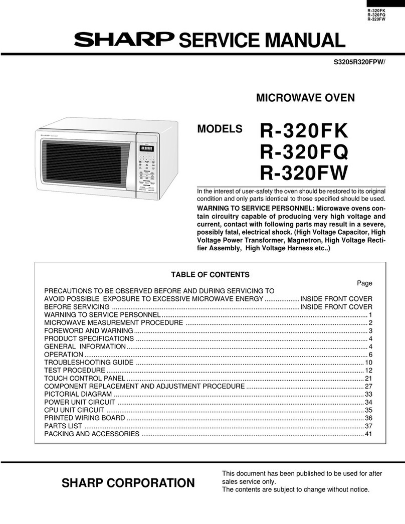
R-3A56(W)
R-3A56(B)
CAUTION
MICROWAVE
RADIATION
Personnel
should
not
be
exposed
to
the
mircowave
energy
which
may
radiate
from
the
magnetron
or
other
microwave
generating
devices
if it
is
improperly
used
or
connected.
All
input
and
output
micro-
wave
connections,
waveguides,
flanges
and
gaskets
must
be
secured.
Never
operate
the
device
with-
out
a
microwave
energy
absorbing
load
attached.
Never
look
into
an
open
waveguide
or
antenna
while
the
device
is
energised.
VARNING
MIKROVAGSSTRALING
Personal
far
inte
utsattas
for
mikrovagsenergi
som
kan
utstrala
fran
magnetronen
eller
andre
mikrovagsalstrande
anordningar
om
dessa
4r
felanslutna
eller
anvands
pa
fel
satt.
Alla
in-och
utgangsanslutningar
for
mikrovagor,
vagledare,
flansar
och
packningar
maste
vara
fast
anslutna.
Mikrovagsgeneratorn
far
inte
arbeta
utan
att
absorberande
belastning
ar
ansluten.
Titta
aldrig
ini
en
dppen
vagledare
eller
antenn
nar
mikrovagsgeneratorn
ar
pakopplad
eller
laddad.
=
VAROITUS
MIKROAALTOSATEILYA
Kayttaja
ei
saa
joutua
alttiiksi
mikroaaltoenergialle,
jota
voi
sateilla
magnetronista
tai
muusta
mikroaaltoja
kehittavasta
laitteesta,
jos
sita
kaytetaan
vaarin
tai
jos
se
kytketaan
vaarin.
Kaikkien
mikroaaltoliitantéjen
seka
sy6ttd-etta
ulostulopuolella,
aaltoputkien
laippojen
ja
tiivisteiden
tulee
olla
varmistettuja.
Mikroaaltouunia
ei
koskaan
saa
kayttaa
ilman
kuormaa
jossa
mikroaaltoenergiaa
kuluu.
Avoimeen
aaltoputkeen
tai
antenniin
ei
koskaan
saa
katsoa
virran
ollessa
kytkettyna.
ADVARSEL
—
MIKROBOLGESTRALING
Personell
ma
ikke
utsettes
for
mikrobglge-energi
som
kan
utstrales
fra
magnetronen
eller
andre
mikrobelge-generende
deler
dersom
apparatet
feilbetjenes
eller
blir
feiltikoplet.
Atle
inn-og
ut-
tilkoplinger
i
forbindelse
med
mikrobalge-stralingen,
belgeledere,
flenser
og
tetningsringer/pakninger
ma
festes
ordentlig.
Aldri
bruk
apparatet
med
mindre
en
mikrobalge-absorberende
last
er
plassert
i
ovnsrommet.
Aldrise
direkte
inn
i
en
Apen
belgeleder
eller
antenne
imens
apparatet
er
stramfgrende.
ADVARSEL
MIKROBOLGEBESTRALING
Man
bor
ikke
udszette
sig
for
mikrobalgebestraling
fra
magnetronen
eller
andre
mikrobglgefrembringende
anordninger,
hvilket
kan
ske
hvis
apparatet
er
forkert
tilsluttet
eller
bruges
forkert.
Alle
mikrobelgeindgange
og-udgange,
baigeledere,
flanger
og
tezetningsstrimler
ma
veere
forsvarligt
udfgrt.
Anvend
aldrig
ovnen
uden
en
mikrobelgeabsorberende
anordning.
Se
aldrig
ind
i
en
Aben
bgigeleder
eller
antenne,
mens
ovnen
er
i
brug.
SERVICE
MANUAL
SHARP
MICROWAVE
OVEN
R-3A56(W)
/
R-3A56(B)
GENERAL
IMPORTANT
INFORMATION
This
Manual
has
been
prepared
to
provide
Sharp
Corp.
Service
Engineers
with
Operation
and
Service
Information.
It
is
recommended
that
service
engineers
carefully
study
the
entire
text
of
this
manual,
so
they
will
be
qualified
to
render
satisfactory
customer
service.
The
parts
marked
"*"
are
used
at
voltage
more
than
250V.
(Parts
List)
Delar
market
med
"*“
har
en
spanning
éverstigande
250V.
Huolto-chjeeseen
merkitty.
"tahdelia"
osat
joissa
jannite
on
yli
250V.
Deler
som
er
merket
“asterisk”
er
utsatt
for
spenninger
over
250V
til
jord.
Dele
mzerket
med
stjerne
benyttes
med
hojere
speending
end
250
volt.
WARNING
Never
operate
the
oven
until
the
following
points
are
ensured.
(A)
The
door
is
tightly
closed.
(B)
The
door
brackets
and
hinges
are
not
defective.
(C)
The
door
packing
is
not
damaged.
(D)
The
door
is
not
deformed
or
warped.
(E)
There
is
not
any
other
visible
damage
with
the
oven.
Servicing
and
repair
work
must
be
carried
out
only
by
trained
Service
Engineers.
All
the
parts
marked
”*”
on
parts
list
are
used
at
voltages
more
than
250V.
Removal
of
the
outer
wrap
gives
access
to
potentials
above
250V.
SHARP
CORPORATION
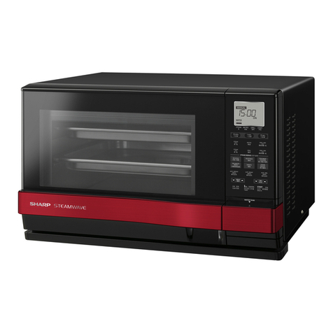
OSAKA,
JAPAN
R-3A56(W)
R-3A56(B)
|
PRODUCT
SPECIFICATION
GENERAL
INFORMATION
APPEARANCE
VIEW
|
OPERATING
SEQUENCE
|
FUNCTION
OF
IMPORTANT
|
COMPONENTS
ISERVICINGAND
~—
|
TROUBLESHOOTING
CHART
t
TEST
PROCEDURE
“~E
TOUCH
CONTROL
PANEL
ADJUSTMENT
PROCEDURE
MICROWAVE
MEASUREMENT
|
TEST
DATA
AT
A
GLANCE
WIRING
DIAGRAM
PARTS
LIST
R-3A56(W)
R-3A56(B)
PRODUCT
SPECIFICATIONS
SPECIFICATION
ITEM
DESCRIPTION
Power
Requirements
220
-230
Volts
50
Hertz
Single
phase,
3
wire
grounded
Power
Consumption
1.5
kW
Power
Output
Q900W
watts
nominal
of
RF
microwave
energy
(measured
by
way
of
IEC
705)
Operating
frequency
of
2450
MHz
Case
Dimensions
Width
450mm
Height
295mm
including
foot
Depth
360mm
=
Cooking
Cavity
Dimensions
Width
290mm
Height
174mm
Depth
313mm
Tumiabie
diameter
Control
Complement
Touch
Control
System
Clock(1:00-12:59
or
0:00-23:59)
Microwave
Power
for
Variable
Cooking
Repetition
Rate;
Full
power
throughout
the
cooking
time
approx.
70%
of
Full
Power
approx.
50%
of
Full
Power
approx.
30%
of
Full
Power
approx.
10%
of
Full
Power
AUTO
MINUTE
pad
START
pad
POWER
LEVEL
pad
STOP/CLEAR
pad
Time
pads
GENERAL
INFORMATION
WARNING
THIS
APPLIANCE
MUST
BE
EARTHED
IMPORTANT
THE
WIRES
IN
THIS
MAINS
LEAD
ARE
COLOURED
IN
ACCORDANCE
WITH
THE
FOLLOWING
CODE:
GREEN-AND-YELLOW
:
EARTH
BLUE
:
NEUTRAL
BROWN
>
LIVE
R-3A56(W)
R-3A56(B)
APPEARANCE
VIEW
OVEN
Door
—
Tumtable
Door
hinges
Waveguide
cover
Contol
panel
Door
lock
openings
————
Roller
stay
Oven
cavity
Door
seals
and
sealing
surfaces
|
Safety
door
latches
Ventilation
openings
0.
Outer
case
1.
Power
supply
cord
A
SOON
DARWN
=
Seal
packing
1.
Place
the
roller
stay
on
the
floor
of
the
oven
cavity.
2.
Then
place
the
turntable
on
it
fitting
to
the
coupling.
THE
AUTO-TOUCH
CONTROL
PANEL
More
Indicator
Less
Indicator
Low
Indicator
Med/Low
indicator
Med
indicator
Med/High
indicator
High
indicator
Digital
display
Pieces
indicator
.
Unit
weight
indicator
.
Cook
indicator
.
Snack
keys
.
Potato
keys
.
Instant
action
keys
.
More/Less
keys
.
Time
keys
.
Timer/Hold
key
.
Clock
set
key
.
Power
level
key
.
Stop
key
.
Auto
minute/Start
key
.
Door
open
button
©
ODNAaAPR
WON
>
[Onn
©
a
a
en
i
N+]
CO
DAN
DAR
WN
=
OC
R-3A56(W)
R-3A56(B)
OPERATING
SEQUENCE
OFF
CONDITION
Closing
the
door
activates
all
door
interlock
switches
(pri-
mary
latch
switch,
2nd
latch
switch
and
stop
switch).
IMPORTANT
When
the
oven
door
is
closed,
the
monitor
switch
contacts
COM
-
NC
must
be
open.
When
the
microwave
oven
is
pluged
in
a
wall
outlet
(240V
50H2),
the
line
voltage
is
supplied
to
the
point
A3+A5
in
the
control
unit.
Figure
O-1
on
page
30
—
.
The
display
flashes
"88:88".
2.
Toset
any
programmes
or
set
the
clock,
you
must
first
touch
the
STOP
pad.
3.
“88:88”
appears
in
the
display
and
the
time
counts
up
every
minute.
NOTE:
When
the
oven
door
is
opened,
the
oven
lamp
comes
on
at
this
time.
MICROWAVE
COOKING
CONDITION
HIGH
COOKING
Enter
a
desired
cooking
time
with
the
touching
Time
pad
and
start
the
oven
with
touching
START
pad.
Function
sequence
Figure
0-2
on
page
30
CONNECTED
COMPONENTS
RELAY
Oven
famp,
Fan
motor,
Turntable
motor
RY1
Power
transformer
RY2
1.
The
line
voltage
is
supplied
to
the
primary
winding
of
the
power
transformer.
The
voltage
is
converted
to
about
3.3
volts
A.C.
output
on
the
filament
winding
and
high
voltage
of
approximately
2000
volts
A.C.
on
the
secondary
winding.
2.
The
filament
winding
voltage
(3.3
volts)
heats
the
magnetron
filament
and
the
high
voltage
(2000
volts)
is
sent
to
the
voltagedoubling
circuit,
where
it
is
doubled
to
negative
voltage
of
approximately
4000
volts
D.C..
3.
The
2450
MHz
microwave
energy
produced
in
the
magnetron
generates
a
wave
length
of
12.24
cm.
This
energy
is
channeled
through
the
waveguide
(transport
channel)
into
the
oven
cavity,
where
the
food
is
placed
to
be
cooked.
4.
When
the
cooking
time
is
up,
a
single
tone
is
heard
and
the
relays
RY1.+
RY2
go
back
to
their
home
position.
The
circuits
to
the
oven
lamp,
power
transformer,
fan
motor
and
turntable
motor
are
cut
off.
5.
When
the
door
is
opened
during
a
cook
cycle,
the
switches
come
to
the
following
condition.
CONDITION
DURING
DOOR
OPEN
SWITCH
CONTACT
COOKING
=
(NO
COOKING)
Primary
latch
switch
COM-NO
Closed
Open
Monitor
switch
COM-NC
Open
Closed
2nd
latch
switch
COM-NO
Closed
Open
Stop
switch
COM-NO
Closed
Open
The
circuits
to
the
power
transformer,
fan
motor
and
turntable
motor
are
cut
off
when
the
primary
latch
switch,
2nd
latch
switch
and
stop
switch
are
made
open.
The
oven
jamp
remains
on
even
if
the
oven
door
is
opened
after
the
cooking
cycle
has
been
interrupted,
because
the
relay
RY1
stays
closed.
Shown
in
the
display
is
the
remaining
time.
6.
MONITOR
SWITCH
CIRCUIT
The
monitor
switch
(SW3)
is
mechanically
controlled
by
oven
door,
and
monitors
the
operation
of
the
1st
latch
switch
(SW1)
6-1
When
the
oven
door
is
opened
during
or
after
the
cycle
of
cooking
program,
the
primary
latch
switch
(SW1),
and
stop
switch
(SW4)
must
open
their
contacts
first.
After
that
the
contacts
(COM
-
NC)
of
the
monitor
switch
(SW3)
can
be
closed
and
then
contacts
of
the
2nd
latch
switch
(SW2)
can
be
opened.
6-2
When
the
oven
door
is
closed,
the
contacts
(COM
-
NC)
of
the
monitor
switch
(SW3)
must
be
opened
and
contacts
(COM
-
NO)
of
the
2nd
latch
switch
(SW2)
must
be
closed
first.
After
that
the
contacts
of
the
primary
latch
switch
(SW1)
and
stop
switch
(SW4)
are
closed.
6-3
When
the
oven
door
is
opened
and
the
contacts
of
the
primary
latch
switch
(SW1)
remain
closed,
the
fuse
(F)
F7.4A
will
blow,
because
the
monitor
switch
is
closed
and
a
short
circuit
is
caused.
HIGH,
MEDIUM
HIGH,
MEDIUM,
MEDIUM
LOW,
LOW
COOKING
When
the
microwave
oven
is
preset
for
variable
cooking
power,
the
line
voltage
is
supplied
to
the
power
transformer
intermittently
within
a
32-second
time
base
through
the
relay
contact
which
is
coupled
with
the
current-limiting
relay
(RY2).
The
following
levels
of
microwave
power
are
given.
SETTING
32
sec.
ON
HIGH
24
sec.
ON
8
sec.
OFF
MEDIUM
HIGH
Approx.
70%
=
630
Watts
18
sec.
ON
14
sec.
OFF
‘
MEDIUM
kx
°°»
&
|
Approx.
50%
=
450
Watts
-
12
sec.
ON
20
sec.
OFF
MEDIUM
LOW
Approx.
30%
=
270
Watts
6
sec.
ON
30
sec.
OFF
NOTE:
The
ON/OFF
time
ratio
does
not
exactly
correspond
to
the
percentage
of
microwave
power,
because
approx.
2
seconds
are
needed
for
heating
up
the
magnetron
filament.
R-3A56(W)
R-3A56(B)
FUNCTION
OF
IMPORTANT
COMPONENTS
DOOR
OPEN
MECHANISM
The
door
can
be
opened
by
pushing
the
door
open
button
on
the
control
panel.
When
the
door
open
button
is
pushed,
the
cook
lever
is
moved
upward,
operating
the
latch
head.
The
latch
head
is
moved
upward,
and
released
from
the
latch
hook.
Now,
the
door
can
be
opened.
DOOR
STOP
SWITCH
LATCH
HOOK
2ND
LATCH
SWITCH
MONITOR
SWITCH
LATCH
HEADS
pamany
LATCH
CH
OPEN
LEVER
DOOR
OPEN
BUTTON
Figure
D-1.
Door
Open
Mechanism
PRIMARY
LATCH
SWITCH
(SW1)
2ND
LATCH
SWITCH
(SW2)
apr
SWITCH
(SW4)
.
When
the
oven
door
is
closed,
the
contacts
(COM
-
NO)
must
be
closed.
2.
When
the
oven
dooris
opened,
the
contacts
(COM
-
NO)
must
be
opened.
MONITOR
SWITCH
(SWS)
1.
When
the
oven
door
is
closed,
the
contacts
(COM
-
NC)
must
be
opened.
2.
When
the
oven
door
is
opened,
the
contacts
(COM
-
NC)
must
be
closed.
3.
If
the
oven
door
is
opened
and
the
contacts
(COM
-
NO)
of
the
primary
latch
switch
(SW1)
fail
to
open,
the
fuse
F7.4A
blows
simultaneously
with
closing
the
contacts
(COM
-
NC)
of
the
monitor
switch
(SW3).
CAUTION:
BEFORE
REPLACING
A
BLOWN
FUSE
(F)
F7.4A
TEST
THE
PRIMARY
LATCH
SWITCH
(SW1),
MONITOR
SWITCH
(SW3)
AND
MONITOR
RESISTOR
FOR
PROPER
OPERATION.
(REFER
TO
CHAPTER
"TEST
PROCEDURE”.)
MONITOR
RESISTOR
0.80hm
20W
The
monitor
resistor
prevents
the
maximum
breaking
ca-
pacity
of
the
F7.4A
fuse
from
being
exceeded
due
to
operation
of
the
monitor
switch
ASYMMETRIC
RECTIFIER
The
asymmetric
rectifier
is
a
solid
state
device
that
prevents
current
flow
in
both
directions.
And
it
prevents
the
tempera-
ture
rise
of
the
power
transformer
by
blowing
the
special
fuse
F7.4A
when
the
high
voltage
rectifier
is
shorted.
ASYMMETRIC
Le
RECTIFIER
HIGH
VOLTAGE
RECTIFIER
The
rated
peak
reverse
voltage
of
D1
of
the
asymmetric
rectifier
is
6
KV.
The
rated
peak
reverse
voltage
of
D2
of
the
asymmetric
rectifier
is
1.7
KV.
D1
and
D2
of
the
asymmetric
rectifier
or
high
voltage
rectifier
are
shorted
when
the
each
peak
reverse
voltage
goes
beyond
the
each
rated
peak
reverse
voltage.
(The
process
of
blowing
the
fuse
F7.4A.)
1.
The
high
voltage
rectifier
is
shorted
by
anycauses
when
microwave
cooking
or
dual
cooking.
2.
The
peak
reverse
voltage
of
D2
of
the
rectifier
goes
beyond
the
rated
peak
reverse
voltage
1.7
KV
in
the
voltage
doubler
circuit.
.
D2
of
the
rectifier
is
shorted.
.
The
large
electric
currents
flow
through
the
high
voltage
winding
of
the
power
transformer.
5.
The
large
electric
currents
flow
through
the
primary
winding
of
the
power
transformer.
.
The
fuse
F7.4A
blows
by
the
large
electri
currents.
7.
The
power
supply
to
the
power
transformer
is
cut
off.
mee)
ao
Pagar
F7.4A
The
fuse
F7.4A
blows
when
the
contacts
((OM-
NO)
of
the
primary
latch
switch
(SW1)
remain
cls
ed
with
the
oven
door
open
and
when
the
monitor
switch
(SWS)
closes.
2.
The
fuse
F7.4A
also
blows
when
asymmetric
rectifier,
H.V.
rectifer,
H.V.
wire
harness,
H.\.
capacitor,
magnetron
or
secondary
winding
of
powe
transformer
is
shorted.
3.
If
the
wire
harness
or
electrical
components
are
short-
circuited,
the
fuse
F7.4A
blows
to
prevent
an
electric
shock
or
fire
hazard.
THERMAL
CUT-OUT
145°C
TC1
(MG)
The
thermai
cut-out
protects
the
magnetron
against
ove
r-
heat.
if
this
temperature
goes
up
higher
tha
145°C
be-
cause
the
fan
motor
is
interrupted,
the
ventilaio
n
openings
are
blocked,
the
thermal
cut-out
(TC1)
will
men
and
line
voltages
to
the
power
transformer
will
be
cut
off
and
the
operation
of
the
magnetron
will
be
stopped.
Th
©
defective
thermal
cut-out
(TC1)
must
be
replaced
withnéw
one.
R-3A56(W)
R-3A56(B)
THERMAL
CUT-OUT
125°C
TC2
(OVEN)
The
thermal
cut-out
located
on
the
top
of
the
oven
cavity
is
designed
to
prevent
damage
to
the
oven
if
the
foods
in
the
oven
catch
fire
due
to
over
heating
produced
by
unproper
setting
of
cook
time
or
failure
of
control
unit.
Under
normal
operation,
the
oven
thermal
cut-out
remains
closed.
How-
ever,
when
abnormally
high
temperatures
are
reached
within
the
oven
cavity,
the
oven
thermal
cut-out
will
open
at
125°C,
causing
the
oven
to
shut
down.
The
defective
thermal
cut-out
(TC2)
must
be
replaced
with
new
one.
TURNTABLE
MOTOR
The
turntable
motor
drives
the
turntable
roller
assembly
to
rotate
the
turntable.
FAN
MOTOR
The
fan
motor
drives
a
blade
which
draws
external
cool
air.
This
cool
air
is
directed
through
the
air
vanes
surrounding
the
magnetron
and
cools
the
magnetron.
This
air
is
channeled
through
the
oven
cavity
to
remove
steam
and
vapours
given
off
from
the
heating
foods.
It
is
then
ex-
hausted
through
the
exhausting
air
vents
at
the
oven
cavity.
NOISE
FILTER
The
noise
filter
prevents
the
radio
frequency
interference
that
might
flow
back
in
the
power
circuit.
R-3A56(W)
R-3A56(B)
SERVICING
WARNING
TO
SERVICE
PERSONNEL
Microwave
ovens
contain
circuitry
capable
of
producing
very
high
voltage
and
current,
contact
with
following
parts:
High
voltage
capacitor,
Power
transformer,
Magnetron,
High
voitage
rectifier
assembly,
High
voltage
harness.
REMEMBER
TO
CHECK
3D
REMEMBER
TO
CHECK
4R
.
1)
Reconnect
all
leads
removed
from
components
1)
Disconnect
the
supply.
during
testing.
2)
Door
opened,
and
wedged
open.
2)
Replace
the
outer
case
(cabinet).
3)
Discharge
high
voltage
capacitor.
3)
Reconnect
the
supply.
WARNING
AGAINST
THE
CHARGE
OF
THE
4)
Run
the
oven.
Check
all
functions.
HIGH-VOLTAGE
CAPACITOR
Microwave
ovens
should
not
be
run
empty.
To
test
for
the
presence
of
microwave
energy
within
a
cavity,
place
a
cup
of
cold
water
on the
oven
turntable,
close
the
door
and
set
the
microwave
timer
for two
(2)
minutes.
Set
the
The
high-voltage
capacitor
remains
charged
about
60
seconds
after
the
oven
has
been
switched
off.
Wait
for
60
seconds
and
then
short-circuit
the
power
level
to
HIGH
and
push
the
START
button.
When
connection
of
the
high-voltage
capacitor
(that
is,
of
the
connecting
lead
of
the
high-voltage
recti-
fier)
against
the
chassis
with
the
use
of
an
insu-
lated
screwdriver.
the
two
minutes
has
elapsed
(timer
at
zero)
carefully
check
that
the
water
is
now
hot.
If
the
water
remains
cold
carry
out
3D
checks
and
re-examine
the
connections
to
the
component
being
tested.
Sharp
recommend
that
wherever
possible
fault-finding
is
carried
out
with
the
supply
disconnected.
It
may
in,
some
cases,
be
necessary
to
connect
the
supply
after
the
outer
case
has
been
removed,
in
this
event
carry
out
3D
checks
and
then
disconnect
the
leads
to
the
primary
of
the
power
transformer.
Ensure
that
these
leads
re-
main
isolated
from
other
components
and
the
oven
chassis.
(Use
insulation
tape
if
necessary.)
When
the
testing
is
completed
carry
out
3D
checks
and
reconnect
the
leads
to
the
primary
of
the
power
transformer.
When
all
service
work
is
completed,
and
the
oven
is
fully
assembled,
the
microwave
power
output
shouldbe
checked
and
a
microwave
leakage
test
carried
out.
TROUBLESHOOTING
GUIDE
When
troubleshooting
the
microwave
oven,
it
is
helpful
to
IMPORTANT:
If
the
oven
becomes
inoperatve
because
follow
the
Sequence
of
Operation
in
performing
the
checks.
of
a
blown
fuse
F7.4A
in
the
prirmary
latch
Many
of
the
possible
causes
of
trouble
will
require
that
a
switch
-
monitor
switch
-
moritor
resistor
specific
test
be
performed.
These
tests
are
given
a
proce-
circuit,
check
the
primary
lach
switch,
dure
letter
which
will
be
found
in
the
"Test
Procedure”
monitor
switch
and
monitor
resistor
before
section.
replacing
the
fuse
F7.4A.
R-3A56(W)
R-3A56(B)
[esr
proceune
JA]
8]
COE
[EEE]
Flap
[sa
Mi
epluilulel2imi]s|]r]el|nimMielr
AlolvivilrRInilo|tilHluloloitalu
clwl|.]|.trlolnwlo]lels|rininie
N|E
clmM]|.{/i}]e}]erielsia
N
E}R|R]A;Aalilt
M
E/|t|mM{T
E/PirR{|Alols|aler
olola
POSSIBLE
CAUSE
R/TtTlc}lajly}lTr]R{/|wilcel]
7]/rl]
eit
s
AND
Pree
ale
colabale
taal
LI
a
c
L/R]
RIE
DEFECTIVE
PARTS
N|
FI
TIA
wilclu|]*/tle
sS}/1}o]Tt{]s]i]H}]
tr]
Ale]s
M
FIlE{R|cilwli|t
l
R
|
I
O
Oo}
R
H]/1ic¢
0
S
T
R
TI
H
U
T
O
MIA
sic
T
O
R
E|
S
wl
R
R|
Ss
1
E
T
M
Cc
B
H
L
Y
PROBLEM
Home
fuse
blows
when
power
cord
is
plugged
into
wall
outlet.
Fuse
F7.4A
blows
when
power
cord
is
plugged
into
wall
outlet.
“88:88”
dose
not
appear
in
display
when
power
cord
is
plugged
into
wall
outlet.
Display
does
not
operate
properly
when
STOP/CLEAR
pad
is
touched.
OFF
CONDITION
Oven
lamp
does
not
light
when
door
is
opened.
(Display
appears.)
:)
Oven
does
not
start
when
START
pad
is
touched.
(Display
appears
Oven
lamp
does
not
light.
(Display
appears.)
Fan
motor
does
not
operate.
(Display
appears.)
Turntable
motor
assembly
does
not
operate.
(Display
appears.)
Oven
or
electrical
parts
do
not
stop
when
cooking
time
is
0
or
STOP
pad
is
touched.
Oven
seems
to
be
operating
but
little
or
no
heat
is
produced
in
oven
load.
(Microwave
power
level
is
set
at
"HIGH”)
Oven
does
not
operate
properly
during
the
variable
cooking
condition
except"HIGH”
cooking
condition.
(Oven
stops
when
STOP
pad
is
touched.)
Oven
goes
into
cook
cycle
but
shuts
down
before
end
of
cooking
cycle.
COOKING
CONDITION
Oven
stops
as
soon
as
the
START
pad
is
touched.