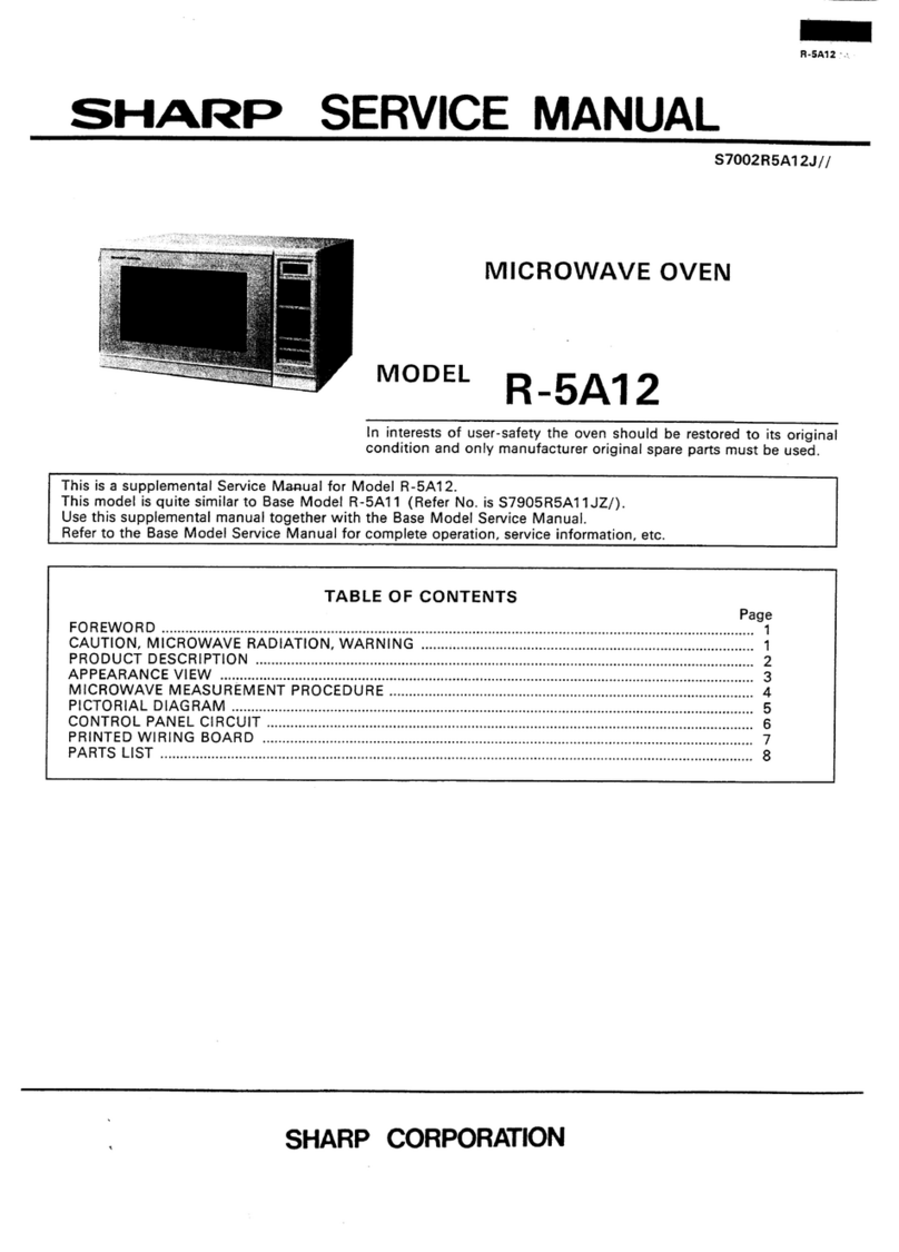
Sharp R-4A56 User manual

R-4A56
SHARP CORPORATION
SERVICE MANUAL
In interests of user-safety the oven should be restored to its original
condition and only parts identical to those specified should be used.
MODEL R-4A56
S8406R4A56PJZ
MICROWAVE OVEN
TABLE OF CONTENTS Page
CAUTION, MICROWAVE RADIATION ................................................................................................................ 1
WARNING..............................................................................................................................................................1
PRODUCT SPECIFICATIONS............................................................................................................................. 2
GENERAL INFORMATION ................................................................................................................................... 2
APPEARANCE VIEW........................................................................................................................................... 3
OPERATION SEQUENCE ................................................................................................................................... 4
FUNCTION OF IMPORTANT COMPONENTS .................................................................................................... 5
SERVICING .......................................................................................................................................................... 6
TEST PROCEDURE ............................................................................................................................................ 8
TOUCH CONTROL PANEL ................................................................................................................................ 16
COMPONENT REPLACEMENT AND ADJUSTMENT PROCEDURE............................................................... 20
MICROWAVE MEASUREMENT ........................................................................................................................ 26
WIRING DIAGRAM ............................................................................................................................................. 27
PICTORIAL DIAGRAM....................................................................................................................................... 29
CONTROL PANEL CIRCUIT .............................................................................................................................. 31
PRINTED WIRING BOARD ................................................................................................................................ 32
PARTS LIST........................................................................................................................................................ 33

R-4A56

R-4A56
1
SERVICE MANUAL
PRODUCT SPECIFICATIONS
SHARP CORPORATION
OSAKA, JAPAN
TEST PROCEDURE
SERVICING AND
TROUBLESHOOTING CHART
FUNCTION OF IMPORTANT
COMPONENTS
OPERATING SEQUENCE
APPEARANCE VIEW
MICROWAVE MEASUREMENT
WIRING DIAGRAM
PARTS LIST
TOUCH CONTROL PANEL
ASSEMBLY
COMPONENT REPLACEMENT
AND ADJUSTMENT PROCEDURE
MICROWAVE OVEN
R-4A56
GENERAL IMPORTANT INFORMATION
ThisManualhasbeenpreparedtoprovideSharpCorp.Service
engineers with Operation and Service Information.
It is recommended that service engineers carefully study the
entire text of this manual, so they will be qualified to render
satisfactory customer service.
CAUTION
MICROWAVE RADIATION
DO NOT BECOME EXPOSED TO RADIATION FROM
THE MICROWAVE GENERATOR OR OTHER PARTS
CONDUCTING MICROWAVE ENERGY.
Serviceengineersshouldnotbeexposedtothemicrowave
energy which may radiate from the magnetron or other
microwave generating devices if it is improperly used or
connected. All input and output microwave connections,
waveguides, flanges and gaskets must be secured. Never
operate the device without a microwave energy absorbing
load attached. Never look into an open waveguide or
antenna while the device is energized.
WARNING
Never operate the oven until the following points are ensured.
(A) The door is tightly closed.
(B) The door brackets and hinges are not defective.
(C) The door packing is not damaged.
(D) The door is not deformed or warped.
(E) There is not any other visible damage with the oven.
Servicing and repair work must be carried out only by trained
service engineers.
All the parts marked "*" on parts list are used at voltages more
than 250V.
Removal of the outer wrap gives access to potentials above
250V.
All the parts marked "∆" on parts list may cause undue
microwave exposure, by themselves, or when they are dam-
aged, loosened or removed.

R-4A56
2
PRODUCT SPECIFICATIONS
GENERAL INFORMATION
WARNING
THIS APPLIANCE MUST BE EARTHED
IMPOTANT
THE WIRES IN THIS MAINS LEAD ARE COLOURED IN ACCORDANCE WITH THE FOLLOWING CODE:
GREEN-AND-YELLOW : EARTH
BLUE : NEUTRAL
BROWN : LIVE
ITEM DESCRIPTION
Power Requirements 240 Volts (for Australia) / 230 - 240 Volts (for New Zealand)
50 Hertz
Single phase, 3 wire earthed
Power Consumption 1.4 kW
Power Output 900 watts nominal of RF microwave energy (IEC 705)
750 watts (2 litre water load)
Operating fequency 2450 MHz
Case Dimensions Width 550 mm
Height 312 mm
Depth 420 mm
Cooking Cavity Dimensions Width 381 mm
Height 210 mm
Depth 411 mm
Turntable diameter 360mm
Control Complement Touch Control System
Clock ( 1:00 - 12:59)
Timer (0 - 99 minutes 99 seconds)
Microwave Power for Variable Cooking
Repetition Rate;
HIGH............................................... Full power throughout the cooking time
MEDIUM HIGH .................................................. approx. 70% of Full Power
MEDIUM .............................................................approx. 50% of Full Power
MEDIUM LOW ....................................................approx. 30% of Full Power
LOW ................................................................... approx. 10% of Full Power
INSTANT ACTION pads
AUTO COOK pad
EASY DEFROST pad
NUMBER pads
SERVE QUANTITY pads
POWER LEVEL pad
MORE, LESS pads
STOP/CLEAR pad
AUTO START/CLOCK pad
INSTANT COOK/START pad
Set Weight Approx. 17 kg

R-4A56
3
APPEARANCE VIEW
1. Ventilation openings
2. Oven lamp
3. Door hinges
4. Safety door latches
5. See through door
6. Coupling
7. Door open button
8. Touch control panel
9. Digital readout
10.Wave guide cover
11.Access cover for oven lamp
replacement
12.Power supply cord
111
10
9
8
12 11 1
74
6
5
32
4
12345
6789O
STOP
CLEAR
AUTO
START
CLOCK INSTANT COOK
START
MORE( ),LESS( )PADS
Presstoincrease/decreasethetime
inoneminuteincrementsduring
cookingortoalterthedonenessfor
theAutoCook,InstantActionor
EasyDefrostmode.
AUTOSTART/CLOCKPAD
PresstosetclockorAutoStarttime.
STOP/CLEARPAD
Presstoclearduringprogramming.
Pressoncetostopoperationof
ovenduringcooking;presstwice
tocancelcookingprograme.
NUMBER PADS
Presstoentercooklingtimes,clock
time,weightorquantityoffood,or
toselecttheAutocookmenus.
EASYDEFROSTPAD
Presstodefrostmeatbyentering
weightonly.
Reheat/Pies/Pastries
1 piece
12345
POWER
LEVEL
EASY
DEFROST
LESS
MORE
2 X 3 X 4 X
AUTOCOOKPAD
PresstoselectAutoCookmode.
AUTOCOOKMENUS
POWERLEVELPAD
Presstoselectmicrowavepower
setting.Ifnotpressed,HIGHis
automaticallyselected.
2,3,or4SERVEQUANTITYPAD
Tocooktwo,three,orfourserves,
pressrequiredpadpriortopressing
theInstantActionpad.
INSTANTCOOK/STARTPAD
Pressoncetocookfor1minuteatHIGH
orincreaseby1minutemultipleseachtime
thispadispressedduringcooking.
Presstostartovenaftersettingprogrammes.
INSTANTACTIONPADS
Pressoncetocook orreheat8
popular menus.
Rice & Pasta
1/2 uup
1 Fresh Vegetables
2 Frozen Vegetables
3 Jacket Potato
4 Roast Lamb
5 Seasoned Roast
6 Desserts
AUTO
COOK
Frozen
Dinner
1 serve
Reheat
Beverage/Soup
1 cup
Chicken
Pieces
1 serve
Bacon
1 serve Casseroles
1 serve Fish Fillets
1 serve
TOUCH CONTROL PANEL

R-4A56
4
OPERATION SEQUENCE
OFF CONDITION
Closing the door activates all door interlock switches
(Upper latch switch, Lower latch switch and Stop switch)
IMPORTANT
When the oven door is closed, the monitor switch contacts
(COM-NC) must be open.
When the microwave oven is plugged in a wall outlet, rated
voltage is supplied to the point (A3+A5) in the control unit.
Figure O-1 on page 27
1. The display flashes “88:88”.
2. Tosetanyprogramsorsettheclock,youmustfirsttouch
the STOP/CLEAR pad.
3. “ : “appearsinthe displayandthe timecountsup every
minute.
NOTE: When the oven door is opened, the oven lamp
comes on at this time.
MICROWAVE COOKING CONDITION
HIGH COOKING
EnteradesiredcookingtimewiththetouchingNumberpads
and start the oven with touching START pad.
Function sequence
Figure O-2 on page 28
CONNECTED COMPONENTS RELAY
Oven lamp, Fan motor, Turntable motor RY1
Power transformer RY2
1. Rated voltage is supplied to the primary winding of the
powertransformer.Thevoltageisconvertedtoabout3.3
volts A.C. output on the filament winding and high
voltageofapproximately2000voltsA.C.onthesecondary
winding.
2. The filament winding voltage (3.3 volts) heats the
magnetron filament and the high voltage (2000 volts) is
senttothevoltagedoublingcircuit,whereitisdoubledto
negative voltage of approximately 4000 volts D.C..
3. The 2450 MHz microwave energy produced in the
magnetron generates a wave length of 12.24 cm. This
energy is channelled through the waveguide (transport
channel)intotheovencavity,wherethefoodisplacedto
be cooked.
4. When the cooking time is up, a signal tone is heard and
the relays (RY1+RY2) go back to their home position.
The circuits to the oven lamp, power transformer, fan
motor and turntable motor are cut off.
5. When the door is opened during a cook cycle, the
switches come to the following condition
CONDITION
DURING DOOR OPEN
SWITCH CONTACT COOKING (NOCOOKING)
Upper latch switches COM-NO Closed Open
Lower latch switch COM-NO Closed Open
Monitor switch COM-NC Open Closed
Stop switch COM-NO Closed Open
The circuits to the power transformer, fan motor and
turntable motor are cut off when the upper latch switch,
lower latch switch and stop switch are made open. The
oven lamp remains on even if the oven door is opened
after the cooking cycle has been interrupted, because
therelay(RY1) staysclosed.Shownin the displayisthe
remaining time.
6. MONITOR SWITCH CIRCUIT
The monitor switch is mechanically controlled by oven
door, and monitors the operation of the upper and lower
latch switches.
6-1 Whentheoven door isopenedduringor after thecycle
of a cooking program, the upper latch switch, lower
latch switch and stop switch must open their contacts
first.
Afterthatthecontacts(COM-NC)ofthemonitorswitch
can be closed.
6-2. Whentheoven door isclosed,thecontacts (COM-NC)
of the monitor switch must be opened first, and the
contacts(COM-NO) ofthe stop switchmust beclosed.
After that the contacts of the upper latch switch, lower
latch switch and stop switch are closed.
6-3. When the oven door is opened and the contacts of the
upperlatchswitchandlowerlatchswitchremainclosed.
The fuse M8A will blow, because the monitor switch is
closed and a short circuit is caused.
VARIABLE COOKING
When the microwave oven is preset for variable cooking
power.Ratedvoltageissuppliedtothepowertransformer
intermittently within a 32-second time base through the
relay contact which is coupled with the relay (RY2). The
following levels of microwave power are given.
SETTING;
32 sec. ON
24 sec. ON
18 sec. ON
12 sec. ON
6 sec. ON
8 sec. OFF
14 sec. OFF
20 sec. OFF
26 sec. OFF
HIGH
MEDIUM HIGH
MEDIUM
MEDIUM LOW
LOW
Approx. 70%
Approx. 50%
Approx. 30%
Approx. 10%
NOTE: TheON/OFFtimeratiodoesnotexactlycorrespond
to the percentage of microwave power, because
approx. 2 seconds are needed for heating up the
magnetron filament.

R-4A56
5
FUNCTION OF IMPORTANT COMPONENTS
DOOR OPEN MECHANISM
Thedoorcanbeopenedbypushingthedooropenbuttonon
thecontrolpanel.Whenthedooropenbuttonispushed,the
latch lever is moved upward, operating the latch head. The
latch head is moved upward, and released from the latch
hook. Now, the door can be opened.
MONITOR
SWITCH
UPPER
LATCH
SWITCH
STOP
SWITCH
LOWER
LATCH
SWITCH
LATCH
LEVER PLUNGER
SWICTH
LATCH
HEAD
DOOR
OPEN
BUTTON
LATCH
HEAD
LATCH
HOOK
DOOR
Figure D-1. Door Open Mechanism
UPPER LATCH SWITCH, LOWER LATCH SWITCH
AND STOP SWITCH
1. Whenthe oven door is closed, the contacts (COM -NO)
must be closed.
2. Whentheovendoorisopened,thecontacts(COM-NO)
must be opened.
MONITOR SWITCH
1. When the oven door is closed, the contacts (COM- NC)
must be opened.
2. Whentheovendoorisopened,thecontacts(COM-NC)
must be closed.
3. If the oven door is opened and the contacts (COM- NO)
of the upper and lower latch switches fail to open, the
fuse(M8A)blowssimultaneouslywithclosingthecontacts
(COM-NC) of the monitor switch.
CAUTION: BEFOREREPLACINGABLOWNFUSE(M8A)
TEST THE UPPER AND LOWER LATCH
SWITCHES, MONITOR SWITCH AND MONI-
TORRESISTORFORPROPEROPERATION.
(REFERTOCHAPTER“TESTPROCEDURE”.)
MONITOR RESISTOR (0.8Ω20W)
Themonitorresistorpreventsthefuse(M8A)burstingwhen
the fuse blows due to the operation of the monitor switch.
ASYMMETRIC RECTIFIER
Theasymmetricrectifierisasolidstatedevicethatprevents
currentflow inboth directions. Andit preventsthe tempera-
tureriseofthepowertransformerbyblowingthefuse(M8A)
when the high voltage rectifier is shorted.
The rated peak reverse voltage of D1 of the asymmetric
rectifier is 6 KV The rated peak reverse voltage of D2 of the
asymmetricrectifieris1.7KV.D1andD2oftheasymmetric
rectifier or high voltage rectifier are shorted when the each
peak reverse voltage goes beyond the each rated peak
reverse voltage. (The process of blowing the fuse M8A.)
1. Thehighvoltagerectifierisshortedbyanycauseswhen
microwave cooking.
2. The peak reverse voltage of D2 of the rectifier goes
beyond the rated peak reverse voltage 1.7 KV in the
voltage doubler circuit.
3. D2 of the rectifier is shorted.
4. The large electric currents flow through the high voltage
winding of the power transformer.
5. The large electric currents beyond 8A flow through the
primary winding of the power transformer.
6. The fuse (M8A) blows by the large electric currents.
7. The power supply to the power transformer is cut off.
THERMAL CUT-OUT 145˚C (OVEN)
The thermal cut-out located on the top of the oven cavity is
designed to prevent damage to the oven if the foods in the
oven catch fire due to over heating produced by improper
setting of cook time or failure of control unit. Under normal
operation, the oven thermal cut-out remains closed. How-
ever, when abnormally high temperatures are reached
within the oven cavity, the oven thermal cut-out will open at
145˚C, causing the oven to shut down. The thermal cut-out
will be close its contacts again when its temperature goes
down lower than -20˚C.
FUSE (M8A)
1. If the wire harness or electrical components are short-
circuited, this fuse blows to prevent an electric shock or
fire hazard.
2. The fuse blows when the asymmetric rectifier, H.V.
rectifier,H.V.wireharness,H.V.capacitor,magnetronor
secondary winding of power transformer is shorted.
3. Thefusealsoblowswhenupperandlowerlatchswitches
remains closed with the oven door open and when the
monitor switch closes.
TEMPERATURE FUSE 150˚C (MG)
Thisfuseprotectsthemagnetronagainstoverheating.Ifthe
temperature goes up higher than 150˚C because the fan
motor is interrupted, the air inlet duct is blocked or the
ventilationopeningsareobstructed,thefuseblowsandputs
the oven out of operation.
The defective fuse must be replaced with new rated one.
D2 D1
ASYMMETRIC
RECTIFIER
HIGH VOLTAGE RECTIFIER
AB
C

R-4A56
6
TURNTABLE MOTOR
The turntable motor drives the turntable roller assembly to
rotate the turntable.
FAN MOTOR
The fan motor drives a blade which draws external cool air.
This cool air is directed through the air vanes surrounding
the magnetron and cools the magnetron. This air is chan-
nelled through the oven cavity to remove steam and va-
pours given off from the heating foods. It is then exhausted
through the exhausting air vents at the oven cavity.
NOISE FILTER (for New Zealand Model)
The noise filter prevents the radio frequency interference
that might flow back in the power circuit.
SERVICING
WARNING TO SERVICE PERSONNEL
Microwave ovens contain circuitry capable of producing very high voltage and current, contact with any part of the
high voltage circuit will result in electrocution. High voltage capacitor, Power transformer, Magnetron, High voltage
rectifier assembly, High voltage harness.
REMEMBER TO CHECK 3D
1) Disconnect the supply.
2) Door opened, and wedged open.
3) Discharge high voltage capacitor.
WARNING: AGAINST THE CHARGE OF THE
HIGH-VOLTAGE CAPACITOR
The high-voltage capacitor remains charged about
60 seconds after the oven has been switched off.
Wait for 60 seconds and then short-circuit the con-
nection of the high-voltage capacitor (that is, of the
connectingleadofthe high-voltage rectifier)against
thechassiswiththe use ofaninsulatedscrewdriver.
Sharp recommend that wherever possible fault-finding
is carried out with the supply disconnected. It may in,
some cases, be necessary to connect the supply after
theoutercasehasbeenremoved,inthiseventcarryout
3D checks and then disconnect the leads to the primary
of the power transformer. Ensure that these leads re-
main isolated from other components and the oven
chassis. (Use insulation tape if necessary.) When the
testing is completed carry out 3D checks and reconnect
the leads to the primary of the power transformer.
REMEMBER TO CHECK 4R
1) Reconnectallleadsremovedfromcomponentsduring
testing.
2) Replace the outer case (cabinet).
3) Reconnect the supply.
4) Run the oven. Check all functions.
Microwave ovens should not be run empty. To test for
thepresenceof microwaveenergywithina cavity, place
acup ofcold water onthe oventurntable, close thedoor
andset themicrowavetimerfortwo(2)minutes.Setthe
powerlevel to HIGHandpush theSTARTbutton. When
the two minutes has elapsed (timer at zero) carefully
checkthatthewaterisnowhot.Ifthewaterremainscold
carry out 3D checks and re-examine the connections to
the component being tested.
Whenallserviceworkiscompleted,and the oven is fully assembled,themicrowavepoweroutputshouldbechecked
and microwave leakage test carried out
When troubleshooting the microwave oven, it is helpful to
follow the Sequence of Operation in performing the
checks. Many of the possible causes of trouble will require
that a specific test be performed. These tests are given a
procedure letter which will be found in the “Test Procedure
“section.
TROUBLESHOOTING GUIDE
IMPORTANT: Iftheovenbecomesinoperativebecauseof
a blown fuse M8A in the upper latch switch
- lower latch switch - monitor switch - moni-
tor resistor circuit, check the upper latch
switch, lower latch switch, monitor switch
and monitor resistor before replacing the
fuse M8A.

R-4A56
7
MAGNETRON
POWER TRANSFORMER
H.V. RECTIFIER ASSEMBLY
HIGH VOLTAGE CAPACITOR
UPPER LATCH SWITCH
LOWER LATCH SWITCH
STOP SWITCH
MONITOR SWITCH
NOISE FILTER (FOR N.Z.)
MONITOR RESISTOR
TEMPERATURE FUSE
THERMAL CUT-OUT
FAN MOTOR
TURNTABLE MOTOR
FUSE M8A
TOUCH CONTROL PANEL
RELAY (RY-1, RY-2)
FOIL PATERN ON P.W.B.
POWER SUPPLY CORD
OVEN LAMP OR SOCKET
HIGH OLTAGE WIRE
SHORTED WIRE HARNESS
OPENED WIRE HARNESS
WALL OUTLET
HOME FUSE OR BREAKER
WRONG OPERATION
MISADJUSTMENT SWITCH
BLOCKED COOLING FAN
BLOCKED VENTILATION OPENING
Home fuse blows when power
supplycordispluggedintowall
outlet.
FUSEM8Ablows when power
supplycordispluggedintowall
outlet.
"88:88"doesnotappearin dis-
play but power supply cord is
plugged into wall outlet.
Display doesnotoperateprop-
erly when STOP/CLEAR pad
is touched.
Oven lamp does not light at
door opened. (Display ap-
pears.)
Oven does not start when the
START pad is touched. (Dis-
play appears)
Oven lamp does not light (Dis-
play appears.)
Fan motor does not operate.
(Display appears.)
Turntablemotorassemblydoes
notoperate.(Displayappears.)
Oven or any electrical parts
does not stop when cooking
time is 0 or STOP/CLEAR pad
is touched.
Oven seems to be operating
butlittle or no heatisproduced
inovenload.(Microwavepower
level is set at HIGH)
Oven does not seems to be
operating properly when ME-
DIUM HIGH, MEDIUM, ME-
DIUM LOW or LOW is set.
(Oven operates properly at
HIGH and then the STOP/
CLEARpadistouchedtheoven
stops.)
Oven goes into cook cycle but
shutsdownbeforeendofcook-
ing cycle.
Oven stops as soon as when
the START pad is touched.
OFF
CONDITION
PROBLEM
CONDITION
POSSIBLE CAUSE
AND
DEFECTIVE PARTS
TEST PROCEDURE
ON
CONDITION
CK = Check / RE = Replace
ABC
D
EEEEFGHHI I JKMNRE RE CK CKCKCK CKCKCK CKCK

R-4A56
8
TEST PROCEDURES
PROCEDURE
LETTER
CARRY OUT 3D CHECKS.
Isolate the magnetron from high voltage circuit by removing all leads connected to filament terminal.
To test for an open circuit filament use an ohmmeter to make a continuity test between the magnetron
filament terminals, the meter should show a reading of less than 1 ohm.
To test for short filament to anode condition, connect ohmmeter between one of the filament terminals
and the case of the magnetron (ground). This test should be indicated an infinite resistance. If a low or
zero resistance reading is obtained then the magnetron should be replaced.
MICROWAVE OUTPUT POWER (1 Litre water load)
The following test procedure should be carried out with the microwave oven in a fully assembled
condition (outer case fitted). Microwave output power from the magnetron can be measured by way of
IEC 705, i.e. it can be measured by using water load how much it can be absorbed by the water load.
Tomeasurethemicrowaveoutputpower in themicrowave oven,therelationofcalorieandwattis used.
When P(W) heating works for t(second), approximately P x t/4.187 calorie is generated. On the other
hand, if the temperature of the water with V(ml) rises ∆T (°C) during this microwave heating period, the
calorie of the water is V x ∆T.
NEVER TOUCH ANY PART IN THE CIRCUIT WITH YOUR HAND OR AN INSULATED TOOL
WHILE THE OVEN IS IN OPERATION.
AMAGNETRON TEST
The formula is as follows;
P x t / 4.187 = V x ∆T P (W) = 4.187 x V x ∆T / t
Our condition for water load is as follows:
Room temperature..............around 20°C PowersupplyVoltage.........Ratedvoltage
Water load.........1000 g Initial temperature...........10±2°C Heating time.........47 sec.
P = 90 x ∆T
Measuring condition:
1. Container
The water container must be a cylindrical borosilicate glass vessel having a maximum material
thickness of 3 mm and an outside diameter of approximately 190 mm.
2. Temperature of the oven and vessel
The oven and the empty vessel are at ambient temperature prior to the start the test.
3. Temperature of the water
The initial temperature of the water is (10±2)°C.
4. Selectthe initial andfinal watertemperatureso thatthemaximum differencebetweenthe finalwater
temperature and the ambient temperature is 5˚C.
5. Select stirring devices and measuring instruments in order to minimize addition or removal of heat.
6. Thegraduationofthethermometermustbe scaled by 0.1°C at minimumand accuratethermometer.
7. The water load must be (1000±5) g.
8. “t” is measured while the microwave generator is operating at full power. Magnetron filament heat-
up time is not included.
NOTE: The operation time of the microwave oven is “t + 2” sec. 2 sec. is magnetron filament heat-up time.
Measuring method:
1. Measure the initial temperature of the water before the water is added to the vessel.
(Example: The initial temperature T1 = 11°C)
2. Add the 1 litre water to the vessel.
3. Place the load on the centre of the shelf.
4. Operate the microwave oven at HIGH for the temperature of the water rises by a value ∆T of
(10 ±2)˚C.
5. Stir the water to equalize temperature throughout the vessel.
COMPONENT TEST

R-4A56
9
TEST PROCEDURES
PROCEDURE
LETTER COMPONENT TEST
6. Measure the final water temperature. (Example: The final temperature T2 = 21°C)
7. Calculate the microwave power output P in watts from above formula.
Initial temperature.................................................................................................. T1 = 11°C
Temperature after (47 + 2) = 49sec....................................................................... T2 = 21°C
Temperature difference Cold-Warm .................................................................... ∆T1 = 10°C
Measured output power
The equation is “P = 90 x ∆T”....................................................... P = 90 x 10°C = 900 Watts
JUDGMENT: The measured output power should be at least ±15 % of the rated output power.
CAUTION: 1°C CORRESPONDS TO 90 WATTS REPEAT MEASUREMENT IF THE POWER IS
INSUFFICIENT.
1000g
1000g
1000g
T1˚C T2˚C
Heat up for 49 sec.
MICROWAVE OUTPUT POWER (2 Litre water load)
The following test procedure should be carried out with the microwave oven in a fully assembled
condition (with outer case fitted).
Microwave output power from the magnetron can be measured by way of substitution, i.e. it can be
measured by using a water load how much it can be absorbed by the water load. To measure the
microwave output power in the microwave oven, the relation of calorie and watt is used.
Ontheotherhand,ifthetemperature of the waterwith V(ml)rises∆T(˚C)duringthis microwave heating
period, the calorie of the water is V x ∆T.
The formula is as follows;
P = 8330 x ∆T/t
Our condition for water load is as follows:
Room temperature..............23±2˚C Power supply Voltage.........Rated voltage
Water load.........2000 ml Initial temperature...........23±1˚C Heating time .1 min. 51sec.
P = 75 x ∆T
Measuring method:
A) The two water containers must be prepared.
Thewatercontainermustbeone(1)litrebeakermadeofPyrex glassanditsdiameterapproximately
12cm.
B) Putthe one (1)litre water intoeachbeaker (Eachbeakerhas onelitrewater). Theinitialtemperature
of the water should be 23±1˚C.
C) Mark T1 on the one beaker and mark T2 on the other one. And stir the water and measure the
temperature of water the thermometer and note them. The graduation of the thermometer must be
scaled by 0.1˚C at minimum and an accurate mercury thermometer is recommended.
D) Place the two (2) beakers as touching each other in the centre of the oven cavity.
E) Set the timer to 1 minutes and 51 seconds, start the oven at 100% power.
F) The time must be measured with stopwatch or wristwatch.
G) After 1 minutes and 51 seconds, stop the oven by opening the door.
H) Put the two (2) beakers out of the oven cavity and measure the temperature of the water by stirring
the water with thermometer and note them.

R-4A56
10
TEST PROCEDURES (CONT'D)
BPOWER TRANSFORMER TEST
WARNING: Highvoltagesandlargecurrentsarepresentatthesecondarywindingandfilament
winding of the transformer. It is very dangerous to work near this part when the
oven is on. NEVER make any voltage measurements of the high-voltage circuits,
including the magnetron filament.
CARRY OUT 3D CHECKS.
Disconnect the leads to the primary winding of the power transformer. Disconnect the filament and
secondarywindingconnectionsfromtherestoftheHVcircuitry.Usinganohmmeter,setonalowrange,
it is possible to check the continuity of all three windings. The following readings should be obtained:
a. Primary winding ................... approx. 1.54 Ω
b. Secondary winding............... approx. 84.8 Ω
c. Filament winding .................. less than 1Ω
Ifthereadingobtainedarenotstatedasabove,thenthepowertransformerisprobablyfaultyandshould
be replaced.
CARRY OUT 4R CHECKS.
C HIGH VOLTAGE RECTIFIER ASSEMBLY TEST
HIGH VOLTAGE RECTIFIER TEST
CARRY OUT 3D CHECKS.
Isolate the high voltage rectifier assembly from the HV circuit. The high voltage rectifier can be tested
using an ohmmeter set to its highest range. Connect the ohmmeter across the terminal B+C of the high
voltage rectifier and note the reading obtained. Reverse the meter leads and note this second reading.
The normal resistance is infinite in one direction and more than 100 kΩin the other direction.
Example
Initial temperature .............................................................................T1 = 23˚C T2 = 24˚C
Temperature after 1 min. 51 sec. ..................................................... T1 = 33˚C T2 = 34˚C
Temperature difference Cold-Warm.............................................. ∆T1 = 10˚C ∆T2 = 10˚C
Mean temperature rise ∆T......................... ∆T = (∆T1 ±∆T2) / 2 = (10˚C+10˚C) / 2 = 10˚C
Measured output power
The equation is P= 75 x ∆T ......................................................... P= 75 x 10˚C =750 Watts
NOTE: The measured output power should be at least ±15 % of the rated output power.
CAUTION: 1˚C CORRESPONDS TO 75 WATTS. REPEAT MEASUREMENT IF THE POWER IS
INSUFFICIENT.
COMPONENT TEST
PROCEDURE
LETTER
1 l 1 l
(T1 C) (T2 C)
1 l 1 l
(T1 C) (T2 C)
Heat up for 1min. 51 sec.
1 litre 1 litre 1 litre 1 litre

R-4A56
11
TEST PROCEDURES (CONT'D)
CARRY OUT 4R CHECKS.
ASYMMETRIC RECTIFIER TEST
CARRY OUT 3D CHECKS.
Isolate the high voltage rectifier assembly from the HV circuit. The asymmetric can be tested using an
ohmmeter set to its highest range across the terminals A+B of the asymmetric rectifier and note the
reading obtained. Reverse the meter leads and note this second reading. If an open circuit is indicated
in both direction then the asymmetric rectifier is good. If an asymmetric rectifier is shorted in either
direction,thentheasymmetricrectifierisprobablyfaultyandmustbereplacedwithhighvoltagerectifier.
Whentheasymmetricrectifierisdefective,checkwhethermagnetron,highvoltagerectifier,highvoltage
wire or filament winding of the power transformer is shorted.
CARRY OUT 4R CHECKS.
NOTE: FOR MEASUREMENT OF THE RESISTANCE OF THE RECTIFIER, THE BATTERIES OF THE
MEASURING INSTRUMENT MUST HAVE A VOLTAGE AT LEAST 6 VOLTS, BECAUSE
OTHERWISE AN INFINITE RESISTANCE MIGHT BE SHOWN IN BOTH DIRECTIONS.
PROCEDURE
LETTER COMPONENT TEST
AB
C
D2 D1
ASYMMETRIC
RECTIFIER
HIGH VOLTAGE RECTIFIER
D HIGH VOLTAGE CAPACITOR TEST
CARRY OUT 3D CHECKS.
A. Isolate the high voltage capacitor from the circuit.
B. Continuity check must be carried out with measuring instrument which is set to the highest resistance
range.
C. Anormalcapacitorshowscontinuityforashorttime(kick)andthenaresistanceofabout10MΩafterithas
been charged.
D. A short-circuited capacitor shows continuity all the time.
E. An open capacitor constantly shows a resistance about 10 MΩbecause of its internal 10MΩresistance.
F. When the internal wire is opened in the high voltage capacitor shows an infinite resistance.
G. The resistance across all the terminals and the chassis must be infinite when the capacitor is normal.
If incorrect reading are obtained, the high voltage capacitor must be replaced.
CARRY OUT 4R CHECKS.
ESWITCH TEST
CARRY OUT 3D CHECKS.
Isolate the switch to be tested and using an ohmmeter check between the terminals as described in the
following table. Table: Terminal Connection of Switch
Plunger Operation COM to NO COM to NC
Released O.C. S.C.
Depressed S.C. O.C.
COM; Common terminal,
NO; Normally open terminal
NC; Normally close terminal
S.C.; Short circuit
O.C.; Open circuit
If incorrect readings are obtained, make the necessary switch adjustment or replace the switch.
CARRY OUT 4R CHECKS.
FNOISE FILTER TEST
CARRY OUT 3D CHECKS.
Disconnect the leads from the terminals of the noise
filter.Usinganohmmeter,check between theterminals
as described in the following table. L (min) Cx ±20% Cy ±20%
1.0 mH 0.068µF 2200pF
If incorrect readings are ob-
tained,replacethenoisefilter
unit.
CARRY OUT 4R CHECKS.
MEASURING POINT INDICATION OF OHMMETER
Between N and L Open circuit
Between terminal N and WHITE Short circuit
Between terminal L and RED Short circuit
L
NL
L
M8A
Cx
Cy RED
WHT

R-4A56
12
PROCEDURE
LETTER COMPONENT TEST
TEST PROCEDURES (CONT'D)
GMONITOR RESISTOR TEST
CARRY OUT 3D CHECKS.
Disconnecttheleadsfromthemonitorresist.Usinganohmmeterandsetonalowrange.Checkbetween
the terminals of the monitor resistor.
The resistance of monitor resistor is approx. 0.8 ohms.
If incorrect readings are obtained, replace the monitor resistor.
CARRY OUT 4R CHECKS.
H TEMPERATURE FUSE OR THERMAL CUT-OUT TEST
CARRY OUT 3D CHECKS.
Disconnect the leads from the terminals of the temperature fuse or thermal cut-out. Then using an
ohmmeter, make a continuity test across the two terminals as described in the table below.
CARRY OUT 4R CHECKS .Table: Thermal cut-out Test
Temperature of "ON" condition Temperature of "OFF" condition Indication ofohmmeter
Parts Name (closed circuit) (˚C) (open circuit) (˚C) (When room temperature
is approx. 20˚C)
Thermal cut-out 145˚C -20˚C Above 145˚C Closed circuit.
Temperature fuse 150˚C This is not resetable type Above 150˚C Closed circuit.
If incorrect readings are obtained, replace the temperature fuse or thermal cut-out.
Anopencircuittemperature fuse 150˚C(MG)indicatesthatthe magnetron hasoverheated,thismaybe
due to restricted ventilation, cooling fan failure or a fault condition within the magnetron or HV circuit.
An open circuit thermal cut-out 145˚C (OVEN) indicates that the foods in the oven may catch fire, this
may be due to over heating produced by improper setting of the cooking time or failure of the control
panel.
CARRY OUT 3D CHECKS.
Disconnect the leads from the motor.
Using an ohmmeter, check the resistance between the two terminals as described in the table below.
IMOTOR WINDING TEST
Table: Resistance of Motor
Motors Resistance
Fan motor Approximately 295 Ω
Turntable motor Approximately 12.5 kΩ
If incorrect readings are obtained, replace the motor.
CARRY OUT 4R CHECKS.
LIVE TEST FOR MOTOR WINDINGS
CAUTION: THE FOLLOWING PROCEDURE REQUIRES THE OVEN TO BE CONNECTED TO THE
SUPPLYAND SHOULDONLY BE USEDIF THERELEVANT “COLD” CHECKSFOR THE
MOTOR UNDER TEST ARE INCONCLUSIVE.
1. CARRY OUT 3D CHECKS.
2. Disconnect the leads from the primary of the power transformer. Make sure that the leads remain
isolated from other oven components and chassis. (Use insulation tape if necessary.)
3. Connect a voltmeter, set to 250V AC, across the motor terminals. (Refer to the relevant motor test
procedure or pictorial diagram for the correct terminal numbers.)
4. Arrange the meter in a position where it can be read during the test.
(Do not touch the meter, meter leads or oven circuitry while the oven is active.)

R-4A56
13
TEST PROCEDURES (CONT'D)
PROCEDURE
LETTER COMPONENT TEST
5. Close the oven door.
6. Set the power level to HIGH and set the relevant timer for about three (3) minutes.
7. Note the reading on the meter and carefully observe the motor under test to see if it is turning.
8. CARRY OUT 3D CHECKS.
9. Remove test meter leads.
10.Reconnect the leads to the primary of the power transformer.
If a reading of the line voltage was obtained (step 7) but the motor was not turning then it is faulty and
shouldbereplaced.If the meterindicatedthatnosupplywaspresentthenthewiringtothemotorshould
be checked for continuity.
JBLOWN FUSE F M8A
CARRY OUT 3D CHECKS.
1. If the fuse M8A is blown, there could be shorts or ground in electrical parts or wire harness.
Check them and replace the defective parts or repair the wire harness.
2. If the fuse M8A is blown when the door is opened, check the upper latch switch, lower latch switch,
monitor switch and monitor resistor.
IfthefuseM8Aisblownbyincorrectdoorswitchingreplacethedefectiveswitch(s)andthefuseM8A.
3. Ifthe fuseM8A isblown, therecould bea shortin the asymmetric rectifier or there couldbe aground
in wire harness. A short in the asymmetric rectifier may have occurred due to short or ground in H.V.
rectifier, magnetron, power transformer or H.V. wire. Check them and replace the defective parts or
repair the wire harness.
CARRY OUT 4R CHECKS.
CAUTION: ONLY REPLACE FUSE M8A WITH THE CORRECT VALUE REPLACEMENT
The touch control panel consists of circuits including semiconductors such as LSI, ICs, etc. Therefore,
unlike conventional microwave ovens, proper maintenance cannot be performed with only a voltmeter
and ohmmeter.
In this service manual, the touch control panel assembly is divided into two units, Control Unit and Key
Unit, and troubleshooting by replacement is described according to the symptoms indicated.
1. Key Unit.
The following symptoms indicate a defective key unit. Replace the key unit.
a) When touching the pads, a certain pad produces no signal at all.
b) When touching a number pad, two figures or more are displayed.
c) When touching the pads, sometimes a pad produces no signal.
2. Control Panel
The following symptoms indicate a defective control unit. Replacing the control unit.
2-1 In connection with pads.
a) When touching the pads, a certain group of pads do not produce a signal.
b) When touching the pads, no pads produce a signal.
2-2 In connection with indicators
a) At a certain digit, all or some segments do not light up.
b) At a certain digit, brightness is low.
c) Only one indicator does not light.
d) The corresponding segments of all digits do not light up; or they continue to light up.
e) Wrong figure appears.
f) A certain group of indicators do not light up.
g) The figure of all digits flicker.
2-3 Other possible troubles caused by defective control unit.
a) Buzzer does not sound or continues to sound.
b) Clock does not operate properly.
c) Cooking is not possible.
d) Proper temperature measurement is not obtained.
K TOUCH CONTROL PANEL ASSEMBLY TEST

R-4A56
14
TEST PROCEDURES (CONT'D)
PROCEDURE
LETTER COMPONENT TEST
IfthedisplayfailstoclearwhentheSTOP/CLEARpadisdepressed,firstverifytheribbonismakinggood
contact,verifythatthedoorsensingswitch(stopswitch)operatesproperly;thatisthecontactsareclosed
whenthedoorisclosedandopenwhenthedoorisopen.Ifthedoor sensingswitch(stopswitch)isgood,
disconnect the flat ribbon that connects the key unit to the control unit and make sure the door sensing
switch is closed (either close the door or short the stop switch connecter). Use the Key unit matrix
indicated on the control panel schematic and place a jumper wire between the pins that correspond to
the STOP/CLEAR pad making momentary contact. If the control unit responds by clearing with a beep
the key unit is faulty and must be replaced. If the control unit does not respond, it is a faulty and must
bereplaced. Ifaspecificpaddoesnotrespond,theabovemethodmaybeused(afterclearingthecontrol
unit) to determine if the control unit or key pad is at fault.
L KEY UNIT TEST
KEY UNIT
STOP
CLEAR
POWER
LEVEL
G-12
G-11
G-10
G-9
G-8 G-7 G-6 G-5 G-4 G-3 G-2 G-1
LESS
MORE
1
234
5
67
890
AUTO
COOK
AUTO
START
CLOCK
EASY
DEFROST
Reheat
Beverage
/Soup
INSTANT
COOK
START
Rice
&
Pasta
Frozen
Dinner
4 X 3 X 2 X
Bacon
Casseroles Chicken
Pieces
Reheat
Pie/
Pastries
Fish
Fillets
MRELAY TEST
1. CARRY OUT 3D CHECKS.
2. Disconnect the leads from the primary of the power transformer, Make sure that the leads remain
isolated from other oven components and chassis. (Use insulation tape if necessary)
3. Close the door.
4. Reconnect the supply.
5. Check the voltage between Pin Numbers 3 and 5 of 3-pin connector (A) on the control unit with an
A.C. voltmeter. The meter should indicated 240 volts, if no cheak oven circuit.
6. RY1 AND RY2 Test
These are operated by D.C. voltage. Check voltage at the relay coil with a D.C. voltmeter during the
microwave cooking.
DC. voltage indicated ................... Defective relay.
DC. voltage not indicated ................Check diode which is connected to the relay coil. If diode is
good, control unit is defective.
RELAY SYMBOL OPERATIONAL VOLTAGE CONNECTED COMPONENTS
RY1 APPROX. 26.5V D.C. Oven lamp / Turntable motor / Cooling fan motor
RY2 APPROX. 25.8V D.C. Power transformer

R-4A56
15
TEST PROCEDURES (CONT'D)
PROCEDURE
LETTER COMPONENT TEST
N PROCEDURES TO BE TAKEN WHEN THE FOIL PATTERN ON THE PRINTED WIRING BOARD
(PWB) IS OPEN
To protect the electronic circuits, this model is provided with a fine foil pattern added to the primary on
thePWB, this foilpattern actsasa fuse.Ifthe foilpatternis open,followthe troubleshootingguidegiven
below for repair.
Problem: POWER ON, indicator does not light up.
NOTE: At the time of these repairs, make a visual
inspectionofthevaristorforburningdamage
andexaminethetransformerwithtesterfor
the presence of layer short-circuit (check
primary coil resistance). If any abnormal
conditionisdetected,replacethedefective
parts.
CARRY OUT 4R CHECKS.
RY2
S1
3
1
US:RED,CD:GRY
GE:BLK,AS:BRN
D32
(TAB1)
(COM.)
(TAB2)
(H.V.)
(J1)
17
VRS1
T1
D31
(H.V.)
POWER
O.L.,F.M.,T.T.M.,
CN–A
RY1
5731
a
b
d c
STEPS OCCURANCE CAUSE OR CORRECTION
1 The rated voltage is not applied to POWER Check supply voltage and oven main unit.
terminal of CPU connector (CN-A).
2 The rated voltage is applied to primary side Low voltage transformer or secondary circuit defective.
of low voltage transformer. Check and repair.
3 Only pattern at "a" is broken. *Insert jumper wire J1 and solder.
(CARRY OUT 3D CHECKS BEFORE REPAIR)
4 Pattern at "a" and "b" are broken. *Insert the coil RCILF2003YAZZ between "c" and "d".
(CARRY OUT 3D CHECKS BEFORE REPAIR)

16
R-4A56
TOUCH CONTROL PANEL ASSEMBLY
OUTLINE OF TOIUCH CONTROL PANEL
3) Synchronizing Signal Circuit
This power source synchronizing signal is available in
order to compose a basic standard time in the clock
circuit. It accompanies a very small error because it
works on commercial frequency.
4) ACL Circuit
AcircuittogenerateasignalswhichresetstheLSItothe
initial state when power is supplied.
5) Buzzer Circuit
The buzzer is responsive to signals from the LSI to emit
noticingsounds(keytouchsoundandcompletionsound).
6) Door Sensing Switch
A switch to “tell” the LSI if the door is open or closed.
7) Relay Circuit
To drive the magnetron, fan motor, turntable motor and
light the oven lamp.
8) Indicator Circuit
Indicator element is a Fluorescent Display.
Basically, a Fluorescent Display is triode having a
cathode, a grid and an anode. Usually, the cathode of a
Fluorescent Display is directly heated and the filament
serves as cathode.
The Fluorescent Display has 6-digits, 13-segments are
used for displaying figures.
The touch control section consists of the following unit as
shown in the touch control panel circuit.
(1) Key Unit
(2) Control Unit
The principal functions of these units and the signals com-
municated among them are explained below.
Key Unit
The key unit is composed of a matrix, signals generated in
the LSI are sent to the key unit through R00-R03,R10-R13.
When a key pad is touched, a signal is completed through
the key unit and passed back to the LSI through R23,R30-
R32to perform the function that was requested.
Control Unit
Control unit consists of LSI, power source circuit, synchro-
nizingsignalcircuit,ACLcircuit,buzzercircuitandindicator
circuit.
1) LSI
This LSI controls the key strobe signal, relay driving
signal for oven function and indicator signal.
2) Power Source Circuit
This circuit generates voltages necessary in the control
unit.
Symbol Voltage Application
VC -5V LSI(IC1)
VP -29V Fluorescentdisplaytube:Grid
and anode voltage
VF1 3Vac Filamentoffluorescentdisplay
tube
VF2 (VF1 to VF2 voltage)

17
R-4A56
DESCRIPTION OF LSI
LSI(IZA430DR)
The I/O signal of the LSI(IZA430DR) is detailed in the following table.
Pin No. Signal I/O Description
1 D10 OUT Digit selection signal.
Refer to the touch control panel circuit about the relation between signals and digits.
Normally,onepulseisoutputineverysynchronizedsignalperiod,andinputtothegrid
of the fluorescent display.
2 D11 OUT Segment data signals.
Refer to the touch control panel circuit for the relationship between signals and
indicators. Normally, one pulse is output in every synchronized signal period, and
input to the anode of the fluorescent display.
3 TG1 OUT Signal to sound buzzer.
A: key touch sound (0.12sec.).
B: Completion sound (2.4sec.).
4 Vdisp IN Anode (segment) of Fluorescent Display illumination voltage:-29V.
Vp voltage of power source circuit input.
5R00OUT Segment data signal.
Signal similar to D11.
Key strobe signal.
Signal applied to touch-key section. A pulse signal is input to R23,R30-R32terminal
while one of G1 line keys on key matrix is touched.
6R01OUT Segment data signal.
Signal similar to D11.
Key strobe signal.
Signal applied to touch-key section. A pulse signal is input to R23,R30-R32terminal
while one of G2 line keys on key matrix is touched.
7R02OUT Segment data signal.
Signal similar to D11.
Key strobe signal.
Signal applied to touch-key section. A pulse signal is input to R23,R30-R32terminal
while one of G3 line keys on key matrix is touched.
8R03OUT Segment data signal.
Signal similar to D11.
Key strobe signal.
Signal applied to touch-key section. A pulse signal is input to R23,R30-R32terminal
while one of G4 line keys on key matrix is touched.
9R10OUT Segment data signal.
Signal similar to D11.
Key strobe signal.
Signal applied to touch-key section. A pulse signal is input to R23,R30-R32terminal
while one of G5 line keys on key matrix is touched.
10 R11OUT Segment data signal.
Signal similar to D11.
Key strobe signal.
Signal applied to touch-key section. A pulse signal is input to R23,R30-R32terminal
while one of G6 line keys on key matrix is touched.
11 R12OUT Segment data signal.
Signal similar to D11.
Key strobe signal.
Signal applied to touch-key section. A pulse signal is input to R23,R30-R32terminal
while one of G7 line keys on key matrix is touched.
12 R13OUT Segment data signal.
Signal similar to D11.
Key strobe signal.
Signal applied to touch-key section. A pulse signal is input to R23,R30-R32 terminal
while one of G8 line keys on key matrix is touched.
13-15 R20-R22OUT Segment data signal.
Signal similar to D11.

18
R-4A56
Pin No. Signal I/O Description
16 R23IN Signal coming from touch key.
When either one of G9 line keys on key matrix is touched, a corresponding signal out
ofR00-R03,R10-R13willbeinput intoR23.Whennokey is touched,thesignal is held
at "L" level.
17 R30IN Signal coming from touch key.
WheneitheroneofG10linekeysonkeymatrixistouched,acorrespondingsignalwill
be input into R30.
18 R31IN Signal coming from touch key.
WheneitheroneofG11linekeysonkeymatrixistouched,acorrespondingsignalwill
be input into R31.
19 R32IN Signal coming from touch key.
WheneitheroneofG12linekeysonkeymatrixistouched,acorrespondingsignalwill
be input into R32.
20 INT1 IN Signal synchronized with commercial source frequency(50Hz).
This is basic timing for time processing of LSI.
21 GND IN Power source voltage : -5V.
VC voltage of power source circuit input.
22 AVCC IN Connected to GND.
23-24 AN0-AN1 IN Connected to VC.
25 AN2 IN Terminal to used.
26 AN3 IN Input signal which communicates the door open/close information to LSI..
Door closed; "H" level signal.
Door opened; "L" level signal.
27 AVSS IN Connected to VC.
28 RESET IN Auto clear terminal.
Signal is input to reset the LSI to the initial state when power is supplied. Temporarily
set to “H” level the moment power is supplied, at this time the LSI is set. Thereafter
set at “L” level.
29 TEST IN Connected to GND.
30 OSC1 IN Internal clock oscillation frequency input setting.
Theinternalclockfrequencyissetby inserting the ceramic filter oscillationcircuitwith
respect to OSC1 terminal.
31 OSC2 OUT Internal clock oscillation frequency control output.
Output to control oscillation input of OSC2.
32 VCC IN Power source voltage input terminal.
Connected to GND.
33 D0 OUT Terminal to used.
34 D1 OUT Magnetron High-voltage circuit driving signal.
Toturnonandoffthecookrelay).InHIGHoperation,thesignalsholds“H”levelduring
microwave cooking and “L” level while not cooking. In other cooking modes (MED
HIGH,MED,MED LOW,LOW) the signal turns to “H” level and “L” level in repetition
according to the power level.
35 D2 OUT Terminal not used.
36 D3 OUT Oven lamp, turntable motor and cooling fan motor driving signal. (Square
Waveform : 45Hz)
To turn on and off the control relay. The pulse signal (45Hz) is delivered to the control
relay driving circuit and cook relay control circuit.
37 D4 OUT Segment data signal.
Signal similar to D11.
38-42 D5-D9 OUT Digit selection signal.
Signal similar to D10.
Table of contents
Other Sharp Microwave Oven manuals

Sharp
Sharp R-350D User manual

Sharp
Sharp R-308CK User manual

Sharp
Sharp Carousel R-310E User manual

Sharp
Sharp R-261STW Instruction Manual

Sharp
Sharp Carousel R2 K Series User manual

Sharp
Sharp AX-1500X User manual

Sharp
Sharp R-508FS User manual

Sharp
Sharp Carousel R-880F User manual

Sharp
Sharp R-451ZS User manual

Sharp
Sharp R-632 Instruction Manual

Sharp
Sharp R-580D User manual

Sharp
Sharp R-21AT User manual

Sharp
Sharp R-239VNW Technical specifications

Sharp
Sharp R-657 User manual

Sharp
Sharp Carousel R-210H User manual

Sharp
Sharp R-310EK User manual

Sharp
Sharp R-9H58 User manual

Sharp
Sharp R-120DB User manual

Sharp
Sharp R-210AM User manual

Sharp
Sharp R-22GT-F User manual