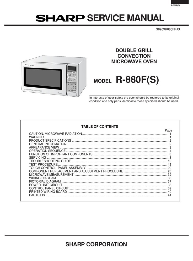
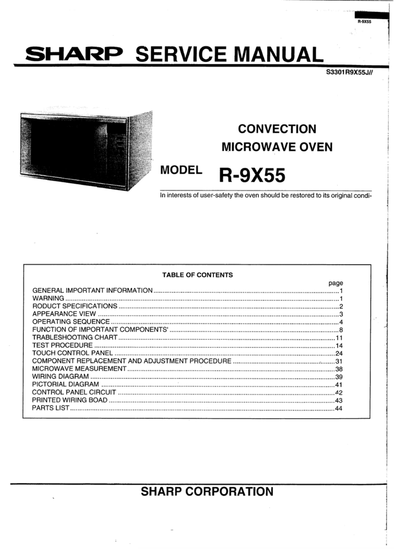
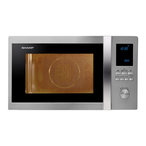
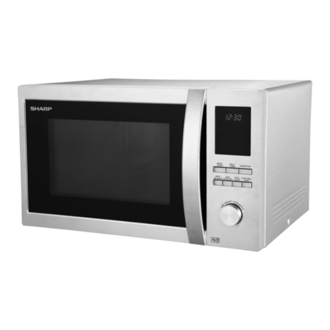
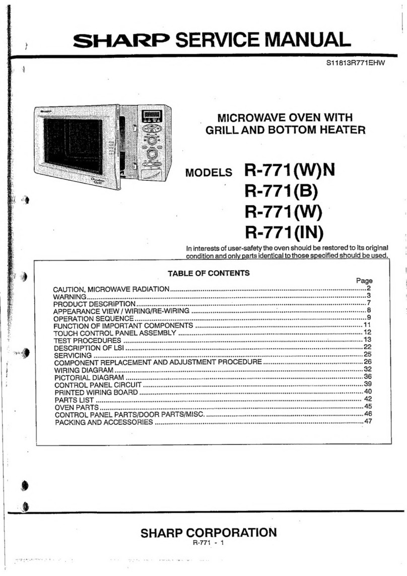
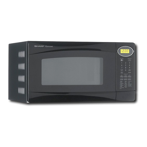
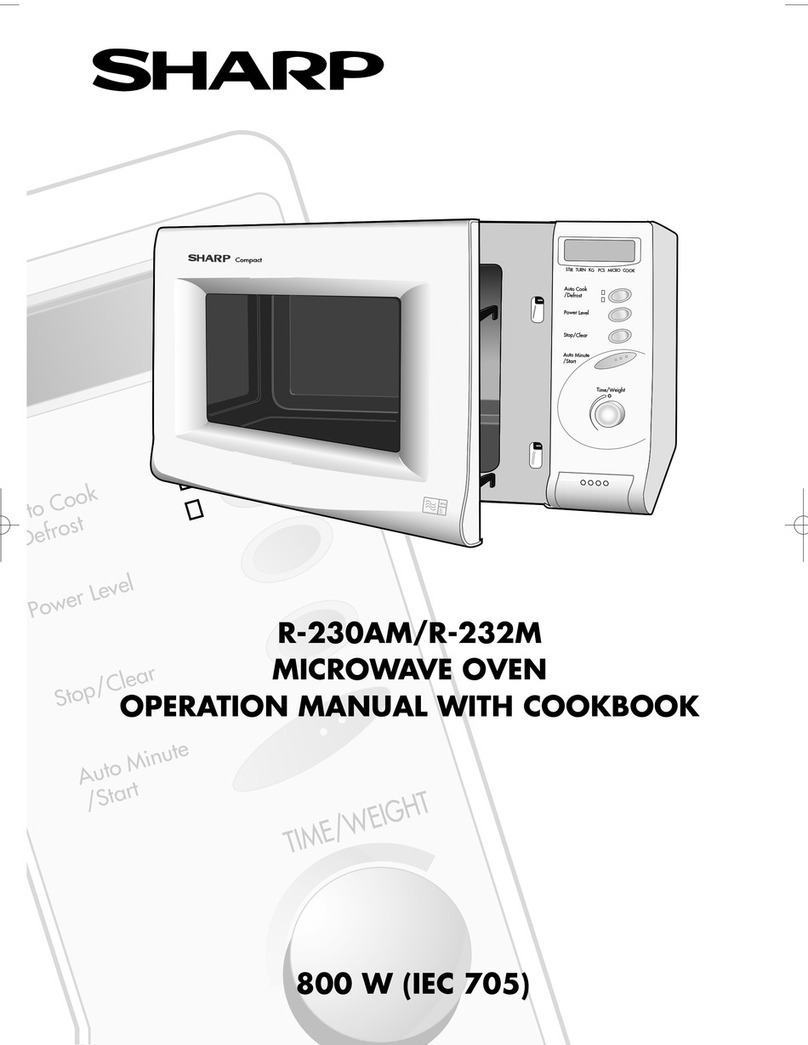
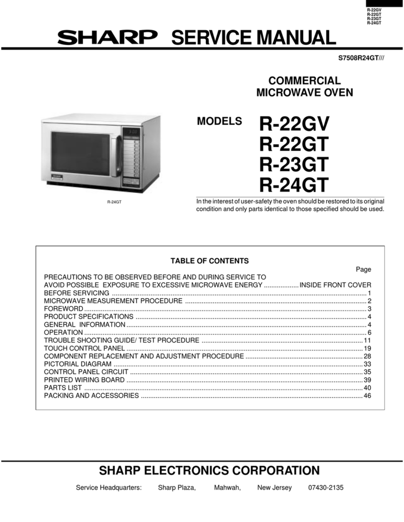
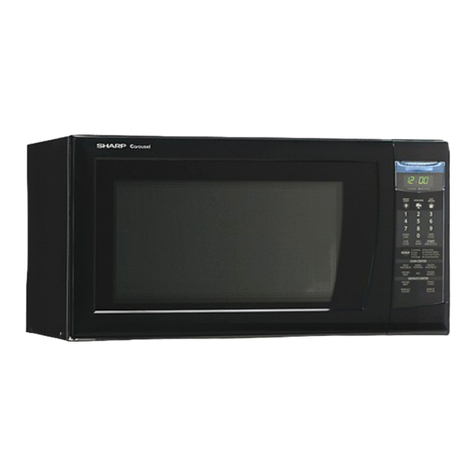
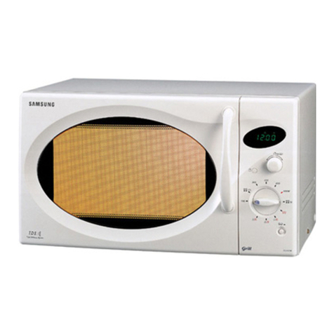
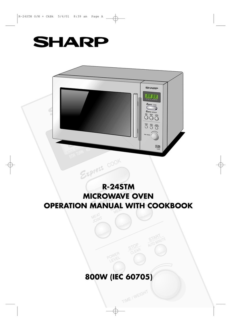
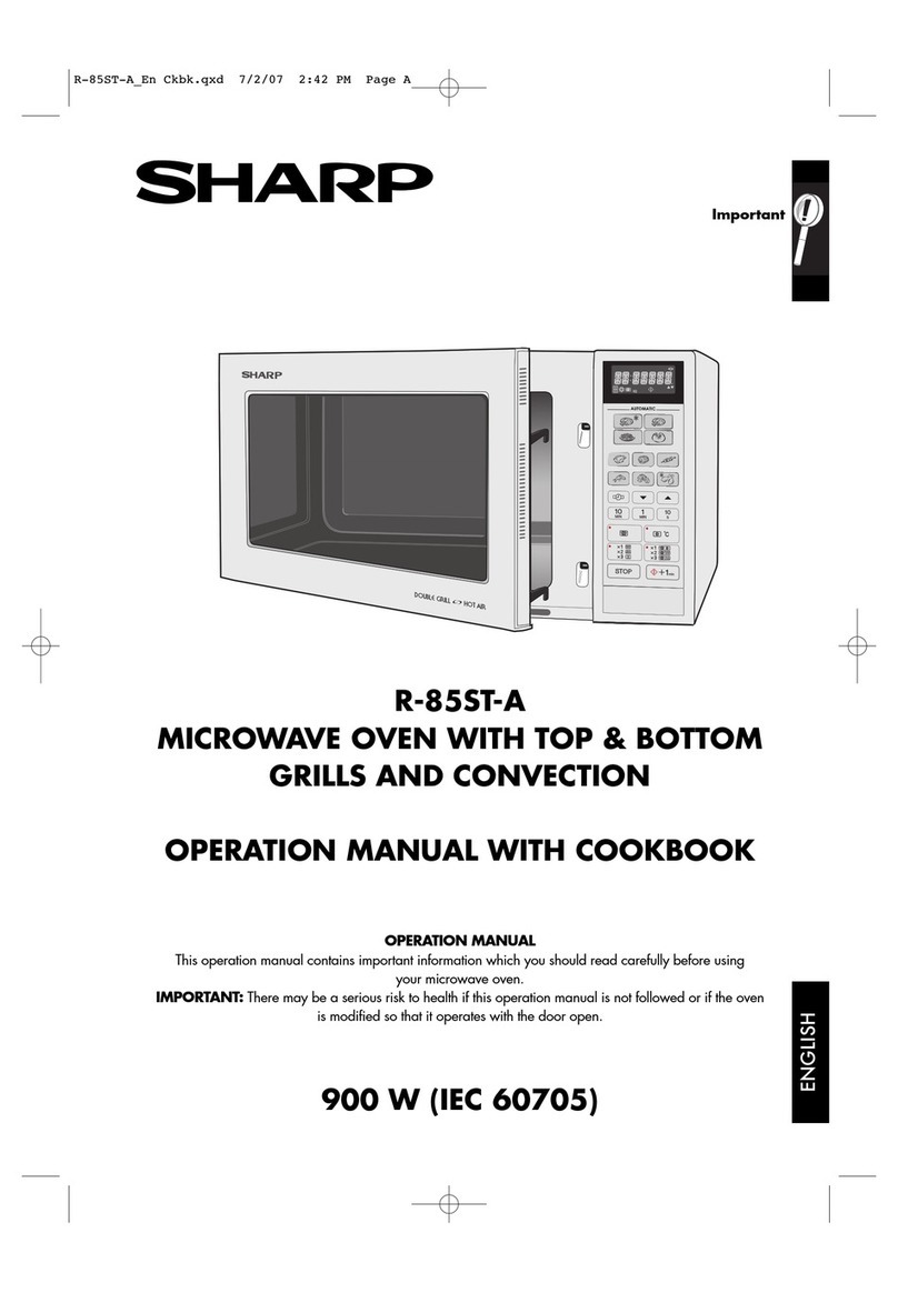
Sharp R-6R50 User manual

SHARP:
SERVICE
MANUAL
3681
8RERS50EHW
GRILL
AND
MICROWAVE
OVEN
MODELS
R-6R50(W)/(B)
R-6G50(W)/(B
R-6G52(W)/(B)
Photo
R-6R50(W)
R
-6R70(W)
/(
B)
In
interests
of
user-safety
the
oven
should
be
restored
to
its
original
condition
and
only
parts
identical
to
those
specified
should
BG
ead
This
is
a
supplemental
Service
Manual
for
Model
R-6R50(W)/(B)
etc.
Those
models
are
quite
similar
to
Base
Model
R-6G10(W)/(B)
(Refer
No.
is
SS809R6G10EHW).
Use
this
supplemental
manual
together
with
the
Base
Model
Service
Manual.
Refer
to
the
Base
Model
Service
Manual
for
complete
operation,
service
information,
etc.
sins
TABLE
OF
CONTENTS
FOREWORD
CAUTION,
MICROWAVE
RADIATION
PRODUCT
DESCRIPTION
GENERAL
INFORMATION
-
OPERATION
INSTRUCTIONS
OPERATION
SERVICING
TOUCH
CONTROL
PANEL
ASSEMBLY
..
COMPONENT
REPLACEMENT
AND
ADJUSTMENT
PROCEDURE
MICROWAVE
MEASUREMENT
PROCEDURE
..
PICTORIAL
DIAGRAM
CONTROL
PANEL
CIRCUIT
PRINTED
WIRING
BOARD
PARTS
LIST
PAGING
AND
ACCESSORIES
SHARP
CORPORATION

R-6G50(B)
R-6R50(W)
R-6R70(W)
R-6R50(B)
R-6R70(B)
R-6R50(W)/(B)
R-6G50(W}/(B)
R-6G62(W)/(B}
R-6R70(W)/(B)
SERVICE
MANUAL
ya
f
%
:
iB
(3
SHARP
PRODUCT
DESCRIPTION
GRILL
AND
MICROWAVE
OVEN
R-6R50(W)/(B)/
R-6G50(W)/(B)/ R-6G52(W)/(B)/
,
R-6R70(W)/(B)
|
FOREWORD
This
Manual
has
been
prepared
to
provide
Sharp
Corp.
Service
Personnel
with
complete
Operation
and
Service
Information
for
the
SHARP
GRILL
AND
MICROWAVE
_
ovens,
R-6R50(W)/(B)/
R-6G50(W)/(B)/
R-6G52(W)/(B)/
R-6R70(W)/(B).
=
The
Models
—_—-
R-6R50(W)/(B)/
R-6G50(W)/(B)/
R-6G52(W)/(B)/
R-6R70(W)/(B)
are
quite
similar
to
Base
Model
R-6G10(W)/(B)
(Refer
No.
SS809R6G10EHW).
It
is
recommended
that
service
personnel
carefully
study
the
a
entire
text
of
this
manual
and
Base
Model
manual,
so
they
will
i
TOUCH
CONTROL
PANEL
be
qualified
to
render
satisfactory
customer
service.
/!
ASSEMBLY
Check
interlock
switches
and
door
seal
carefully.
Special
at-
tention
should
be
given
to
avoid
electrical
shock
and
microwave
radiation
hazard.
COMPONET
REPLACEMENT
AND
ADJUSTMENT
(RD36102U)
--
CAUTION
|
MICROWAVE
RADIATION
oo
MICROWAVE
Personne!
should
not
be
exposed
to
the
microwave
energy
‘MEASUREMENT
which
may
radiate
from
the
magnetron.
or
other
microwave
generating
devices
if it
is
improperly
used
or
connected.
All
input
and
output
microwave
connections,
waveguides,flanges
|
and
gaskets
must
be
secured.
Never
operate
the
device
without
a
microwave
energy
absorbing
load
attached.
Never
look
into
an
open
waveguide
or
antenna
while
the
device
is
energized.
WIRING
DIAGRAM
Note(Parts
List)
:
The
parts
marked
”*”
are
used
in
voltage
more
than
250V.
;
”
7
(nDaez02U)
PARTS
LIST
€
|
|
_
SHARP
CORPORATION
in
OSAKA,
JAPAN

ITEM
Power
Requirements
Power
Consumption
Power
Output
Grill
Heating
element
Power
Output
Case
Dimensions
Cooking
Cavity
Dimensions
Turntable
diameter
Control
Complement
set
Weight
PRODUCT
DESCRIPTION
SPECIFICATION
DESCRIPTION
220
Volts
50
Hertz
Single
phase,
3
wire
earthed
Microwave
cooking
1.25
kW
Dual
cooking
2.55
kW
(Except
R-6R50)
Grill
cooking
1.35
kW
_
600
watts
nominal
of
RF
microwave
energy
(2
ner
water
load)
Operating
frequency
of
2450MHz
1.3
kW
Width
520
mm
Height
341
mm
mnelpeine
foot
Depth
416
mm
Width
340
mm
Height
203
mm
Depth
350
mm
330mm
Touch
Control
System
Clock(
1:00
-
12:59
)
Timer
(0
-
99
min.
99
sec.
)
Microwave
Power
for
Variable
Cooking
Repetition
Rate;
FULL:
POWER®.
-wsssazeesraseazace
Full
power
gusuanaut
the
cooking
time
ROA
cetierersittrcasscetecsei
ve
cocascvcnecs
Sctaab
asics
approx.
70%
of
Full-Power
SSIES”
‘evianshiniewei
canes
vertveeiveaseoetecieveseacaas
approx.
50%
of
Full
Power
.
DEFROST
| -
sasticsaiccedunediceeivestennnnieacetires:
approx.
30%
of
Full
Power
von
ss
aate
dba
aaa
dewearere
Sadie
Calpeata
seukeiite
site:
approx.
We
of
Full
Power
(FUNCTION.
a
ae
Pads
|
ann
med
a
|
Dual
Pads
Gril!
cooking
Rotisserie
Pad’
-
Easy
Defrost
pad
.
Less
/
More
pads
kg
/
Pes
pad
g
pad
|
a
Timer
/
Hold
pad
a
on
|
Auto
Start
/
Clock
pad
sa
as
ae
naa
Stop
/
Clear
pad
Minute
Plus
/
Start
pad
ae
Wa
Numeral
keys
:
10min.
1min.
10sec.
Approx.
23
kg
TE:
.
Numbers
and
letters
shown
after
sentences
such
as
“RD44101U”
are
for
factory
use
only.
2
tt
Hn
(RD44101U)
eae
{i
"
GENERAL
INFORMATION
WARNING
THIS
APPLIANCE
MUST
BE
EARTHED
IMPORTANT
THE
WIRES
IN
THIS
MAINS
LEAD
ARE
COLOURED
IN
ACCORDANCE
WITH
THE
FOLLOWING
CODE:
:
EARTH
:
NEUTRAL
-
:
LIVE
-
.GREEN-AND-YELLOW
BLUE
BROWN
OPERATING
INSTRUCTIONS
R-6G50,.
R-6G52
.
R-6R50,
R-6R70
:
’
dior
Waveguide
cover
Oven
lamp
Access
caver
for
oven
lamp
replacement
.
Ventilation
openings
.
Grill
heater
unit
(See
page
E-19)
Qven
door
with
see-through
window
Doar
latches
Hinges
.
Roller
stay
Removable
turntable
Low
rack
(50
mm}
.
High
rack
(135
mm)
.
Door
open
button{
VW}
.
Auto-Touch
control
panel
.
Digital
readout
.
Skewer
(R-GR50,
R-GR7O
only}
17.
Prongs
(R-6R50,
R-6R70
only)
18.
Skewer
support
{R-6R50,
R-6R70
only)
.
19,
Handles
(R-6R50,
R-6R70
only)
ahs
es
ANMAWNAObDI]GAHD
NOTES:
THE
SKEWER
SUPPORT
IS
FOR
ROTISSERIE
COOKING
ONLY.
AFTER
ROTISSERIE
COOKING
1S
FINISHED,
REMOVE
THE
SKEWER
SUPPORT
AND
STORE
WITH
OTHER
ACCESSORIES.
G@)
Time
pad
;
EASY
DEFROST
pad
Grill
syrnbol
Indicators
@
MICROWAVE
pad
MORE/LESS
pad
AE
ee
Sa
ee
ee
eee
ee.
@.
GRILL
pad...
@
-
Weight
pad
Microwave
and
Defrost.
Digital
display
@
DUAL
COOK
pad
@
TIMER/HOLD
pad
can
@
ROTISSERIE
pad
-
@
AUTO
STARTICLOCK
pad
Rotisserie
symbo!
(A-GRSO,
Indicators
®
Menu
Guide
@
-
STOP/CLEAR
pad
@
COMPUCOOK
pad
@
MINUTE
PLUS/START
pad
R-6R70
only)
EASES
ae
))
Sw
ean]
4OR+
1
byl
eae
rT}
-Siais}+'s
@®
@-
?
£
t
Ba
eee
33
af
sie
,
ofa
}-s
ofeetee*
eer
2m
a
{R-6R50}
(R-6R70)
ae
{R-6G50)
R-6R50(W)
R-6G50(W)
R-6G52(W)
R-6R70(W)
a
(B)
(B)
(B)
{B)
/
f
OPERATION
DESCRIPTION
OF
OPERATING
SEQUENCE
The
following
is
a
description
of
component
functions
during
oven
operation.
(RD74101L)
OFF
CONDITION
Closing
the
door
activates
all
door
interlock
switches
:
ist
latch
switch,
2nd
latch
switch,
heater
switch
and
stop
switch
(In
this
condiction,
the
monitor
switch
COM-INC
contacts
are
opened.)
When
oven
ts
plugged
in,
220
volts
A.C.
is
supplied
to
CPU
unit.
(Figure
0-1)
The
display
will
show
blashing
“88:88”.
To
set
any
program
or
set
the
clock,
you
must
first
*
touch
'
(stop/clear)
pad.
The
display
will
clear,
and
1:00
will
appear
and
count
up
every
minute.
NOTE:
When
the
door
is
opened,
the
oven
lamp
comes
on.
COOKING
CONDITION
FULL
POWER
COOKING
Program
desired
cooking
time
and
Variable
Cooking
Control
by
touching
the
time
pads
and
(
MICROWAVE
)
pad.
When
the
(MINUTE
PLUS/START)
pad
is
touched,
the
following
oper-
ations
occur:
1.
The
contacts
of
relays
are
closed
and
components
connected
to
the
relays
are
turned
on
as
follows.
(For
details,
refer
to
Figure
O-2)
RELAY
CONNECTED
COMPONENTS
RY-1
Oven
lamp/Turntable
motor
RY-2
Power
transformer
RY-4
Fan
motor.
'
RY-5
Rotisserie
motor
Note:
(1)The
surge
relay
(not
shown
above
table)
comes
on
only
for
200
mili
seconds
directly
after
‘MINUTE
PLUS/START‘
pad
touched,
with
closing
its
contacts.
After
that,
the
surge
relay
is.
de-energied.
and
.its.
contacs.
are.
opened.
(2)The
relay
RY-5
is
provided
to
Model
R-GR50-
and
R-6R70
only.
The
rotisserie
motor
is
activated
only
at
the
(ROTISSERIE)
pad
is
touched
befor
touching
the
-
~
(MINUTE
PLUS/START)
pad,
2.
220
volts
A.C.
is
supplied
to
the
primary
winding
of
the
power
transformer
and
is
converted
to
about
3.3
volts
A.C.
output
on
the
filament
winding,
and
approximately
2000
volts
A.C.
on
the
high
voltage
winding.
3.
The
filament
winding
voltage
heats
the
magnetron
filament
and
the
H.V.
winding
voltage
is
sent
to
a
voltage
doubler
circuit.
4,
The
microwave
energy
produced
by
the
magnetron
is
channeled
through
the
waveguide
into
the
cavity
-
feed-box,
and
then
into
the
cavity
where
the
food
is
placed
to
be
cooked.
5.
Upon
completion
of
the
cooking
time,
the
power
transformer,
oven
lamp,
etc.
are
turned
off,
and
the
generation
of
microwave
energy
is
stopped.
The
oven
will
revert
to
the
OFF
condition.
6.
When
the
door
is
opened
during
a
cook
cycle,
the
switches
operate
as
following.
2
ia
|
|
|
|
|
Switch
Contact
During
Door
Cooking
Opened
1st
Latch
Switch
COM-NOQ
Closed
Open
2nd
Latch
Switch
COM-NO
Closed
Open
Heater
Switch
-COM-NO
Closed
Open
Stop
Switch
COM-NO
Closed
Open
Monitor
Switch
COM-NC
Open
Closed
COM-NO
Closed
Open
The
circuits
to
the
turntable
motor,
the
cooling
fan
motor,
the
rotisserie
motor
(for
R-6R50
and
R-6R70),
and
the
high
voltage
components
are
‘
deenergized,
the
oven
lamp
remains
on,
and
the
digital
readout
displays
the
time
stiJl
remaining
in
the
cook
cycle
when
the
door
is
opened.
7.
The
monitor
switch
ts
electrically
monitoring
the
operation
of
the
ist
latch
switch
and
is
mechan-
ically
associated
with
the
door
so
that
it
will
func-
tion
in
the
following
sequence.
(1)
When
the
door
opens
from
a
closed
position,
the
tst
latch
switch
open
that
contacts,
and
then
the
monitor
switch
contacts
(COM-NC)
close.
(2)
When
the
door
is
closed
ae
the
open
posi-
tion,
the
monitor
switch
(COM-NC)
contacts
first
open,
and
then
the
contacts
of
the
1st
latch
switch
close.
If
the
1st
latch
switch
fails
with
its
contacts
closed
when
the
door
is
opened,
the
closing
of
the
monitor
—
switch
contacts
(COM-NC)
wili
form
a
short
circuit
through
the
fuse,
1st
latch
switch,
causing
the
monitor
fuse
to
blow.
ROAST,
SIMMER,
DEFROST,
WARM
COOKING
When
Variable
Cooking
Power
ts
programed,
the
220
volts
A.C.
is
supplied
to
the
power
transformer
~
intermittently
through
the
contacts
of
relay(RY-2)
which
is
operated
by
the
control
unit
within
a
32
sec-
ond
time
base.
Microwave
power
operation
is
as
fol-
lows:
VARI-MODE
ON
TIME
OFF
TIME
FULL
POWER
.
32
sec.
O
sec.
(100%
power)
ROAST
24
sec.
8
sec.
(approx.
70%
Jeet
SIMMER
18
sec.
14
sec.
(approx.
50%
power)
DEFROST
12
sec.
20
sec,
(approx.
30%
power}
WARM
,
6
sec.
26
sec.
(approx.
10%
power)
Note:
The
ON/OFF
time
ratio
does
not
correspond
with
the
percentage
of
microwave
power,
be-
cause
approx.
2
seconds
are
needed
for
heating
of
the
magnetron
filament.
EASY
DEFROST
COOKING
The
EASY
DEFROST
key
is
a
special
function
key
to
defrost
meats
and
other
food
faster
and
better.
EASY
DEFROST
automatically
defrosts
foods.
This
key
has
4
defrost
stages.
When
the
food
weight
is
entered
by
using
the
weight
pads,
the
oven
will
cook
according
to
the
special
cooking
sequence,
refer
to
Easy
Defrost
Chart
on
Op-
eration
Manual.
GRILL
COOKING
CONDITION
In
this
condition
the
food
is
cooked
by
grill
heating
element
energy.
Program
desired
cooking
.time
and
grill
mode
by
~
touching
the
time
pad
and
(GRILL)
pad.
When
the
(MINUTE
PLUS/STAR)
pad
is
touched,
the
grill
heating
element
etc.
come
on
by
ac-
tivating
the
relays,
refer
to
Figure
O-3
for
details.
Note:
(1)For
relay
RY-5,
refer
to
‘Note’
of
*Full
Power
Cook-
ing’
section,
(2)The
relay
RY-4
contacts
hold
ON-condition
and
the
fan
motor
rotate
for
one
minute
after
completion
of
the
grill
cooking
or
dual
cooking,
and
if
the
tem-
perature
of
the
cooling
thermal
cut-out
is
higher
than
100
°C,
the
fan
motor
continues
to
rotate
until
the
temperature
of
the
thermal
cut-out
becomes
lower
than
80
°C.
DUAL
COOKING
CONDITION
(Model
R-6G50,-6G52,-6R70)
In
this
condition
the
food
is
cooked
by
both
microwave
energy
and
grill
heating
element
energy
simultane-
ously.
Program
desired
cooking
time
and
dual
cooking
~
mode
by
touching
the
time
pad
and
the
(DUAL
COOK)
pad.
When
the
(MINUTE
PLUS/START)
pad
is
touched,
the
magnetron
and
the
grill
heating
element
©
etc.
come
on
by
activating
the
relays,
refer
to
Figure
O-5
for
details.
COMPU
COOK
CONDITION
|
COMPU
COOK
automatically
selects
the
cooking
mode
and
compute
the
cooking
timé
for
baking,
roasting
and
grilling.
It
is
based
on
specific
foods
and
the
quantity
or
weight
of
the
food.
Program
the
COMPU
COOK
mode
by
touching
the
(COMPU
COOK)
pad,
enter
the
weight.
of
the
food
by
touching
the
or
(weight)
pad
or
enter
the
quantity
of
the
food
by
touching
the
(weight)
pad,
and
touch
(MINUTE
PLUS/START)
pad.
The
oven
will
generate
the
microwave
energy
and/or
grill
heating
energy
according
to
the
programed
special
cooking
sequence.
R-6R5O(V
R-6G50(¥
R-6G52(¥
R-6R70(V

UOI}IPUOD
Busyoo5
@ABMO4D}
IA}
'Z-O
oin6i.4
meet
ee et
ge
i
:
S352
eet
eet
Se
bag
ans
8
olan
eqgr
Sore
crce
7959-H
PUB
OGH9-H
[epolA
T
wdweowinvys
wawae
1
eee
r-~
'
Hitins
43H
“OakINOl
dvd
re
3
et
|
ANVISISNIG
ALONIN
oa
wats
Ok
Me
ST
G55
oe:
A¥SH
“SING
Q3HONOL
G¥d
=
JTAYAMOUSI
—@
.'|
“diWwwyuo
"Od
AWe
ONINOOA‘2
"Oa501S
100q
‘2
N3AQ
40
NOHIONQS73L0N
DILVINSHaS
sna
P
xoomany
aunt
4
WOMMS
HOLY
aah
oe
me
Mae
oe
€S99-H
PUP
OG59-y
|epo|w
i
BaiWOstue
WMO
t
ee
ru
insu
uatvak
papas
|
Aviwic
xg
TevIdd¥
XID}
T
NZAG
20
WOWIONGS
¢
didn
Pxsoruasa,
avers
™
Le
anaes
Bea
OVEN
SCHEMATICS
Mayon
BOS
wavs
SSVdAR
2NIT
NMoUMd
¢
Hue
HOMASNNGS
ava
oF
0GH9-H.
[epoly
amioy
w1iguagM
naelanovn
a
SO¥CIDA
HOI
Ee
eens
§
peers
|
tyaues
wanwaH
*]
Dae
angias
gy
THROIANL
wales
Haims
y
kounGH
.
sums
MOOSUELNE
AUwetMat
i
HELIA
HOLY?
Peat?
ld
BOL
vevS
F5¥4d40
INIT,
ABCIY™,
PD
BOLIS
Yay
SS0u3
INIT
2HOS~
A0ZS
rr
errr
Tene
a
i,
a”
=
ia
“Gon
WOIWPUOD.
440
“L-O
esnBil4
0SH9-y
lepoW
NOWLINDYHA
anttay
yatateony
Ew)
P
WoWLGA
HOI
WL
NOM
*
HDLUAs
RIOURALAL
ABYHU
A
aascawfieicon
Aostoys#
FT
BOTIwd¥
S3¥JAn
INIT
BOLO¥dWS
Sswala
atit7
OZH9-H
[Epon
Pre]
aoolny
PDIP
ct
SousaNawn
ARYS10A
HOH
=
MaWeGsLiveL
bamce
|
sae
ee
von
Mb
onNG
Shniavaes
Siv2am
anit,
tt
me
ees
ee
ee
ee
-
0£Y9-Y
[Epo
ven
ate
~
aur
5
Wo2s¥d73
Sees
wees
’
peu
zea
Sati
STITT
MOLUIaM
SOLO
i
re
pe
ee
ACSroWN
LPO
-
MOLI
¥dvS
SI¥4L0
EXIT
METH
HOtlvdyo
stoud
ait
ee
—
>
ee,
Watuas
P
x203WaANI
ANYWIal
f
HOM
jana
oti

ce
ee
BIIBSSIJOH
YPIAA
UdHIPUDD
Buyyjoog
1115
“p-EQ
aunbiy
OGH9-
[Spo
MOzST
UOLisad
WOUNOH
€G99-a
PUB
0G59-H
ISpolj
NOKLINOWH
anatmy
Malay
c-—-
at
SBYLTOA
HOIK
;
1
MOLDY
;
L
ER
sine
'
Lue
uzaysH
ST
SOP
FHYIKL
Galv3n
Lo
wanwer
wouade
waaay
suvaiie
akwas
Han
¥
angina
eine
re
aLBVAS/SNId
SLONIW
‘
vd
<ZiHI8SLLOU
"G3HSNOt
O¥d
.
THO
*OWd
SW
SNtHO09
‘2
P
wsctwaine
AMPHIte
I
Hae
WoT
taglines
|LHv2s/snid
aLnaih
‘CIHINGL
Ova
-TUND
"Od
aWLL
ANINOOS-2,
udI}IPUDD
Bupjoog
lend
'G-O
ainbi4
€G59-H
PUB
OGD9-y
[Epo
NOwtaNOYA
aooliry
yataiaae
—
wo
204
-
=
IDVATGA
HOR
“OaHINaL
Ovd
=)
.‘
“GIHONOL
">
@.t
“ASWINVHS
‘aasoig
yood"!
N3A0
JO
NOWIONOI:310N
OYAsHoS
(Hou
ANSE
WEED
BOLO¥déTI
50H3
3N)7
-
—_—--
——
+
-
UOIPUOD
BHulyoos
|]115
“g-o
eanbiy
O0SY9-Hy
I8POW
HOW
SND
Acti
ry
uatatoay
pieces
sausage
Bayiios
Ho
;
O3IHSN01
ava
=)
,'p
Ns
Wa
WAH
“028019
Rood’)
N3A0
30
austayvy*.
bo
SOUIWa¥S
$0uo
3H
we
lava
YOO
.ti¥nd
7
WICTUALHI
Ad
yelia)
OZ4Y9-u
ISPpol
NowaNoTK
Amines
Raat
—s
ee
wrath
a
1
wousvev>
sorlica
HEH
a
1
Araaiva
waiys
!
a
p
Hou
WODUNALAT
AWYiida}
ae
Desay
wast
MOLI
UOLMFIY
WoL
OLY9-H
EPO
HOWLINOYH
ae
wansay
ws
IOVLICA
KOin
f
;
l
wQUIS¥e"d
ot"
wanwasorys
wang
OS
ian
r-7
Fuso
twain
aurea

1ST
LATCH
SWITCH
Operation
is
as
follows.
1.
When
the
door
is
closed,
the
lower
latch
head
snaps
down
above
the
switch
lever.
2.
When
the
lower
latch
head
pushes
the
switch
lever.
The
switch
lever
now
depresses
the
plunger
of
the
switch
closing
its
COM-NO
contacts
(ON
condi-
tion).
3.
When
the
open
button
is
pressed,
it
pushes
the
open
lever.
The
open
lever
raises
the
switch
lever
raising
the
Jower
latch
head.
As
that
time,
the
switch
lever
is
released
from
the
piunger
of
the,
1st
latch
switch.
The
switch
lever
is
returned
to
its
original
position.
Now,
the
COM-NO
contacts
of
the
switch
opened
(OFF
condition).
2ND
LATCH
SWITCH
The
switch
is
activated
by
the
upper
latch
head
on
the
door,
When
the
door
is
opened,
the
switch
interrupts
the
.
circuit
to
the
magnetron
or
heating
element
etc.,
refer
to
Oven
Schematic
Diagram
for
details.
STOP
SWITCH
The
switch
is
activated
by
the
upper
latch
head.
The
contacts
are
opened
at
the
door
opened
and
the
contacts
are
closed
at
the
door
closed.
MONITOR
SWITCH
|
.
The
monitor
switch
is
activated
(the
COM-NC
contacts
opened)
by
the
lower
latch
head
on
the
door
while
the
door
is
closed.
The
switch
is
intended
to
render
the
oven
inoperative
by
means
of
blowing
the
fuse(F6.3A)
when
the
contacts
of
the
1st
latch
switch
fail
to
open
when
the
door
is
opened.
Function
1.
When
the
door
is
opened,
the
monitor
switch
COM-NC
contacts
close
{to
the
ON
condition)
due
©
to
their
being
normaily
closed.
At
this
time
the
1st
latch
switch
is
in
the
OFF
condition
{contacts
open)
due
to
their
being
normally
open
contact
switches.
2.
As
the
door
goes
to
a
closed
position,
the
monitor
switch
COM-NC
contacts
are
first
opened
and
then.
the
1st
latch
switch
contacts
close.
(On
opening
|
the
door,
each
of
these
switches
operate
inversely.)
3.
If
the
door
is
opened,
and
the
1st
latch
switch
contacts
fai]
to
open,
the
fuse
blows
simultane-
ously
with
closing
of
the
monitor
switch
COM-NC
contacts.
CAUTION:
BEFORE
REPLACING
A
BLOWN
FUSE
:
TEST
THE
7ST
LATCH
SWITCH
AND
MONITOR
SWITCH
FOR
PROPER
OP-
ERATION.
(REFER
TO
CHAPTER
“TEST
PROCE-
DURE’),
NOISE
FILTER
UNIT
The-
noise
filter.
unit
prevents
the
radio-frequency:
in-
-.
.
terference.
And
it
has
Fuse,
refer
to
Oven
Schematic
Diagram
for
kind
of
this
fuse.
DESCRIPTION
AND
FUNCTION
OF
COMPONENTS
SURGE
RELAY
AND
SURGE
RESISTOR
Surge
relay
!s
located
on
the
relay
mounting
plate.
Surge
resistor
is
located
on
the
chassis
support.
When
the
cooking
start
button
is
pushed
at
microwave
cooking
or
dual
cooking
condition,
at
first
the
surge
relay
contacts
close
and
the
surge
current
flows
through
the
surge
resistor.
And
then
the
surge
relay
contacts
open
after
approx.
200
msec.
The
surge
resistor
puts
down
the
surge
current.
If
the
surge
resistor
is
open
or
the
surge
relay
does
not
op-
erate,
the
home
breaker,
home
fuse,
fuse
13A
250V
or
fuse
F6.3A
250V
may
break
down
when
the
cooking
Start
button
is
pushed
at
microwave
or
dual
cooking
condition.
ROTISSERIE
COOKING
SYSTEM
.
All
the
surfaces
of
the
food
will
be
able
to
be
grilled
uniformity
by
rotating
the
food
which
the
skewer
is
inserted
into.
~
ROTISSERIE
MOTOR
The
rotisserie
motor
is
located
on
the
rotisserie
motor
angle
assembly
which
is
located
on
the
right
side
wall
of
the
oven
cavity.
The
skewer
is
rotated
by
the
rotisserie
motor
through
the
rotisserie
motor
angle
assembly.
YyP
rt
]e4
ig
Y
1
~
tateh
at!
awilci)
“Se
SS
|
*—
Switch
lever
u
.
Opon
tavor
a)
:
oy
59
Open
bution
Figure
D-1.
Switch
Operation
aa
CAVITY
GRILL
HEATING
ELEMENT
FOOD
ROTISSERIE
OTO.
ASSEMBLY
COUPLING
ROLLER
STAY
ASSEMBLY
Figure
D-2.
Rottisserie
Mechanism
10
R-6R50(V
R-6G50(\
R-6G52(\
R-BR70(V
SERVICING
TROUBLESHOOTING
GUIDE
When
troubleshooting
the
oven,
it
is
helpfull
to
follow
the
Sequence
of
Operation
in
performing
the
checks.
Many
of
the
possible
causes
of
trouble
will
require
that
a
specific
test
be
performed.
These
tests
are
given
a
procedure
Jetter
which
will
be
found
in
the
“Test
Pro-
cedure”
section.
IMPORTANT:
If
the
oven
becomes
inoperative
be-
cause
of
a
blown
fuse
(F6.3A)
in
ist
latch
&
cook
switch
-
the
monitor
switch
circuit,
check
1st
latch
&
cook
switch
and
the
monitor
switch
before
replacing
the
fuse
(F6.3A).
PROBLEM
|
POSSIBLE
CAUSE
|
TEST
PROCEDURE
OR
CORRECTION
Home
fuse
blows
when
power
cord
is
plugged
into
wall
recepta-
cle.
Fuse(13A
250v)
blows
when
power
cord
is
plugged
into
wall
receptacle.
(For
R-6G50,
R-6G52,
R-6R70)
Fuse
F6.3A blows
when
power
cord
ts
plugged
into
wall
recepta-
cle.
:
88:88
do
not
appear
in
diaplay
oa
when
power
supply
cord
is
plugged
into
wail
outlet.
Display
does
not
operate
properly
when
(STOP/
CLEAR)
pad
is
touched.
OFF
CONDITION
Shorted’
wire
in
power
cord
or
wire
har-
|
Replace
cord
or
check
wiring.
ness.
Shorted
wire
in
wire
harness.
Defective
noise
filter
unit.
Defective
monitor
switch.
Shorted
wire
in
wire
harness.
~
Defective
noise
filter
unit.(R-6R50only)
Defective
touch
control
unit
Defective
fuse
13A
250V.(For
R-6G50,
R-6G52,
R-6R70)
|
Defective
fuse
F6.3A..
Defective
magnetron
thermal
cut-out.
Defective
noise
filter
unit.
Defective
touch
control
unit
Defective
stop
switch.
Out
of
adjustment
stop
switch.
|
Oven
lamp
does
not
light
at
door
opened.
No
power
at
outlet.
Open
wire
in
power
cord
or
wire
harness.
Blown
fuse(F6.3A).
Blown
fuse
13A
250V.(For
R-6G52,
R-6R70)
Defective
noise
filter
unit.
Defective
stop
switch.
Defective
oven
tamp.
Defective
oven
lamp
socket.
Defective
touch
control
unit
N
ol
an)
<=
R-6G50,
Defective
magnetron
thermal
cut-out.
Open
or
loose
wire
connection
to
the
above
components.
Check
and
repair
harness,
re-
place
fuse(13A
250V).
Procedure
M.
Procedure
F.
Check
and
repair
harness
and
replace
the
fuse
F6.3A.
-
Procedure
M.
Procedure
P.
Check
and
replace
fuse
13A
Procedure
N.
Procedure
H.
Procedure
M.
.
Procedure
P.
Procedure
E.
Adjust
the
stop
switch.
Check
wall
outlet.
Replace
or
repair.
Procedure
N.
Replace
the
fuse
13A
250V,
~
rocedure
M,
rocedure
E,
eplace
oven
lamp.
eplace
oven
lamp
socket.
rocedure
P,
rocedure
H.
Replace
or
repair
wiring.
—
|
|)
0)
|

-6RS50(W)/(B)
-6R70(W}/{B)
PROBLEM
POSSIBLE
CAUSE
TEST
PROCEDURE
OR
CORRECTION
MINUTE
PLUS/
START
pad
is
pushed,
but
the
oven
does
not
operate
at
Dual
cooking
condi-
tion.
DUAL
COOKING
CONDITION
The
oven
can
not
operate
at
Grill
cooking
condition.
The
oven
can
not
operate
at
Microwave
cooking
condition.
Defective
heater
switch.
Refer
to
“GRILL
COOKING
CONDITION’.
Refer
to
"MICROWAVE
COOKING
CONDITION’,
Procedure
J.
Procedure
P.
check
and
repair
wiring.
Defective
touch
control
unit
Open
or
loose
wiring
to
above
compo-
nents.
MICROWAVE
COOKING
CONDITION
Oven
lamp
does
not
light.
Fan
motor
does
not
rotate
when
MINUTE
PLUS/
START
pad
is
touched.
Turntable
motor
does
not
rotate
when
MINUTE
PLUS/
START
pad
is
touched.
(Oven
lamp
lights.)
Oven
seems
to
be
operating
but
little
or
no
heat
is
produced
in
oven
load.
.
(Microwave
cooking
control
is
set
-|-at
"FULL
POWER”
position.)
.-.
Oven
does
not
cook
properly
when
programmed
for
variabl
cooking
powers.
(Operates
prop-
erly
on
HIGH)
Oven
goes
into
cook
cycle,
but
shuts
down
before
end
of
cycle.
MINUTE
PLUS/
START
pad
is
touched.
Replace
oven
lamp
socket.
Replace
oven
jamp.
Procedure
P.
Replace
or
repair
wiring.
‘Defective
oven
Jamp
socket.
Defective
oven
lamp.
Defective
touch
control
unit
—
Open
or
loose
wire
connection
to
the
above
components.
Defective
fan
motor.
Replace
fan
motor.
Open
or
loose
wiring
to
above
compo-
|
Check
and
repair
wiring.
“
|
nents.
-Oven-stops
as
soon
as
when
the
Defective
touch
control
unit
Procedure
P.
Open
or
loose
wire
connection
to
the
|
Replace
or
repair
wiring.
above
components.
Open
or
loose
wire
connection
to
the
turntable
motor,
1st
latch
switch
or
moni-
tor
switch.
Defective
turntable
motor.
Replace
turntable
motor.
Defective
1st
latch
switch.
Procedure
E.
Defective
heater
thermal
Procedure
H.
R-6R50
only)
Defective
magnetron.
:
Check
and
repair
wiring.
cut-out.
(For
Procedure
A.
Procedure
D.
Procedure
B.
‘|
Procedure
P;
Defective
high
voltage
capacitor.
Defective
power
transformer.
Defective
touch
control
unit
Defective
2nd
latch
switch.
Procedure
E.
Defective
heater
switch.
Procedure
J.
Open
or
loose
wiring
to
above
compo-
|
Check
and
repair
wiring
nents.
Defective
touch
control
unit
Procedure
P.
Magnetron
thermal
cut-out
is
opened.
—
Procedure
H.
Defective
touch
control
unit
Procedure
P.
Fan
motor
stops
;
Check
and
repair
wiring.
Defective
rectifier.
Defective
high
voltage
rectifier
assembly.
R-6R500)
R-6G50(!
R-6G52(1
R-BR70{\
PROBLEM
POSSIBLE
CAUSE
TEST
PROCEDURE
OR
CORRECTION
GRILL
COOKING
CONDITION
When
MINUTE
PLUS/
|
Defective
grill
heating
element.
START
pad
is
touched
but
grill
|
Defective
touch
control
unit
heating
element
does
not
operate.
|
Defective
1st
latch
switch.
(R-6G50,
|
Procedure
E.
R-6G52,
R-6R70)
Defective
1st
latch
and
2nd
latch
switch.
|
Procedure
E.
(R-6R50)
Defective
heater
socket.
Replace
heater
socket.
Defective
heater
switch,
Defective
heater
thermal
cut-out.
Open
or
loose
wire
connection
to
above
|
Check
or
repair
wiring.
components.
The
two
terminals
of
grill
heater
unit
does
|
Check
and
fit
the
two
termi-
not
fit
into
the
heater
socket.
nals
of
grill
heater
unit
into
the
heater
socket,
referring
"TO
INSTALL
THE
GRILL
HEATER
UNIT”.
Defective
touch
control
unit
Procedure
P.
Defective
oven
lamp
socket.
Replace
oven
lamp
socket.
Defective
oven
lamp.
Replace
oven
lamp.
Open
or
loose
wire
connection
to
the
|
Replace
or
repair
wiring.
above
components.
Oven
lamp
does
not
light.
13

|
3-BASO(W)/(B}
R-6R50(
3-6G50(W)/(B}
.
R-6G50{
2-6G52(W)/(B}
t-BR70(W)/(B)
.
,
R-6R70(
PROBLEM
_
POSSIBLE
CAUSE
TEST
PROCEDURE
OR
TEST
PROCEDURES
CORRECTION
:
fee
PROCEDURE
a.
LETTER
COMPONENT
TEST
GRILL
COOKING
CONDITION
(CONT’D)
|
a
F
MONITOR
SWITCH
TEST
|
Disconnect
the
oven
from
the
power
supply.
sae
at
switch
Defective
fan
motor.
Replace
fan
motor.
;
i ‘
RcteEuvetauch
Golan
Procedure
P
Disconnect
the
wire
lead
from
NC
terminal
of
the
monitor
switch.
Before
performing
this
test,
make
sure
i
.
the
1st
latch
switch
is
operating
properly
referring
to
Open
or
loose
wire
connection
to
the
|
Replace
or
repair
wiring
above
components.
“Switch
Test
Procedure”,
Open
or
loose
wire
connection
to
the
|
Check
and
repair
wiring.
Connect
one
ohmmeter
lead
to
NC
terminal
of
monitor
turntable
motor,
1st
latch
switch
or
moni-
switch,
and
the
other
lead
to
COM
terminal
of
monitor
Defective
heater
thermal
cut-out.
(For
|
Procedure
H.
R-6R50
only)
tor
switch.
switch,
as
shown
figure.
When
the
door
is
opened,
the
meter
should
indicate
a
close
circuit.
When
the
plunger
of
monitor
switch
is
pushed
by
a
screw-driver
a
ey
Defective
1st
latch
switch.
Defective
turntable
motor.
Replace
turntable
motor.
Defective
touch
control
unit
through
the
latch
hook
hole
on
the
front
plate
of
the
Defective
rotisserie
motor
assembly.
Replace
rotisserie
motor
assrmbly.
oven
cavity
with
the
door
opened,
the
meter
should
Defective
1st
latch
switch.
indicate
an
open
circuit.
In
case
improper
operation
Defective
.
heater
thermal
cut-out.
(For
|
Procedure
H.
R-6R50
only)
is
indicated,
replace
the
defective
monitor
switch.
eae]
At)
ast
latch
Defective
touch
contro!
unit
Procedure
P.
Fan
motor
does
not
rotate.
2nd
latch
switch
Heater
switch
Turntable
motor
does
not
rotate
when
MINUTE
PLUS/
START
pad
ts
touched.
(Oven
lamp
lights)
The
.
rotisserie.
motor
.
assembly
does
not
oprtate.
(For
R-GR50,
R-6R70)
After
testing
the
monitor
switch,
re-connect
the
wire
lead
to
NC
terminal
of
the
monitor
switch.
eed
L
SURGE
RELAY
TEST
Disconnect
the
connector
from
the
wire
harness
(main).
Afer
stopped
the
grill
cooking,
the
fan
motor
does
not
rotate
for
more
than
1
minute.
(During
cooking,
it
rotates)
When
MINUTE
PLUS/
START
pad
touched,
but
grilt
heating
element
stops
it’s
operate
soon
(after
about
10
minutes).
CONTACTS:
With
12
volts
D.C.
applied
to
the
surge
relay
coil
(1)
and
(6),
a
check
of
contact
with
an
ohmmeter
should
indicated
(3)
and
(5)
sy
contacts
are
closed.
}
Without
12
volts
D.C.
applied
to
the
surge
relay
coil
(1)
and
(6),
tte
an
ohmmeter
should
indicate
those
contacts
are
opened.
If
im-
proper
operation
is
indicated,
replace
the-surge
relay.
If
proper
operation
is
indicated,
check
for
loase
on
broken
wire
connections.
Procedure
H.
Check
fan
blade,
fan
duct,
fan
motor,
air
intake
duct,
partt-
tion
plate,
exhaust
duct,
and
ventilation
openings.
Heater
thermal
cut-out
is
opened.
Thy
4
ta
-
wre.
7
ny
=
COIL:
A
continuity
check
of
the
surge
relay
coil
should
indicate
approxi-
mately
160
©.
If
the
motor
does
not
imdicate
above
ohms,
replace
the
surge
relay.
15

PROCEDURE
TEST
PROCEDURES
(CONT'D)
COMPONENT
TEST
NOISE
FILTER
UNIT
TEST
Disconnect
the
oven
from
the
power
supply.
Connect
ohmmeter
leads
to
connector
N
and
L
on
the
noise
filter
unite,
connector
N
and
white
terminal,
or
connector
L
and
red
terminal.
And
then
measure
the
each
resistance.
;
N
og
WINE
CAOSS
CAPACITOR
,
O,22u/AC2G0V
!
Gaoksonw
LINE
BYPASS
CAPACITOR
LINE
BYPASS
CAPACITOR
0.0047
fAC250V
B07
WACO
10M/0,5W
LINE
CROSS
CAPACITOR
0,1p/AC250V
1.665/0,5M
LINE
BYPASS
CAPACITOR
0.0033
,)/AC250¥
LINE
BYPASS
CAPACITOR
G.0033
pfaczsoy
VOM/IDL
BW
Or
rr
Oe
ere
Gn
a
a
er
Ge
SS
pe
cD
ay
R-6R50
R-6G50/6G52/6R70
MEASURING
POINTS
INDICATION
OF
OHMMETER
Between
connector
N
and
L
-
R-6R50:
Approximately
1.5M
Q
R-6G50/6G52/6R70:
Approximately
680k
Q
lf
the
ohmmeter
does
not
indicate
above
resistance,
replace
the
noise
filter
unit.
In
case
the
ohmmeter
indicates
open
circuit
when
testing
between
connector
L
and
terminal
RED,
check
the
fuse
on the
noise
filter
unit.
If
the
fuse
blows,
replace
it.
TOUCH
CONTROL
PANEL
ASSEMBLY
TEST
The
touch
contro]
panel
consists
of
circuits
including
semiconductors
such
as
LSI,
ICs,
etc.
Therefore,
unlike
conventional
microwave
ovens,
proper
maintenance
cannot
be
performed
with
only
a
voltmeter
and
ohmmeter.
In
this
service
manual,
the
touch
control
panel
assembly
is
di-
vided
into
two
units,
Control
Unit
and
Key
Unit,
trouble
shooting
by
unit
replacement
is
de-
scribed
according
to
the
symptoms
indicated.
1.
Key
Unit.
The
following
symptoms
indicate
a
defective
key
unit.
Replace
the
key.
unit.
a)
When
touching
the
pads,
a
certain
pad
produces
no
signal
at
all.
_
b)
When
touching
a
number
pad,
two
figures
or
more
are
displayed.
_
c)
When
touching
the
pads,
sometimes
a
pad
produces
no
signal.
2.
Control
Unit
2:
The
following
symptoms
indicate
a
defective
control
unit.
Replace
the
contro!
unit.
2-1
In
connection
with
pads.
a)
When
touching
the
pads,
a
certain
group
of
pads
do
not
produce
a
signal.
b)
When
touching
the
pads,
no
pads
produce
a
signal.
2-2
In
connection
with
indicators
;
a)
Ata
certain
digit,
all
or
some
segments
do
not
light
up.
b)
Ata
certain
digit,
brightness
is
low.
c)
Only
one
indicator
does
not
light
up.
©
d)
The
corresponding
segments
of
all
digits
do
not
light
up;
or
they
continue
to
light
up.
e)
Wrong
figure
appears.
.
f)
Accertain
group
of
indicators
do
not
light
up.
g)
The
figure
of
all
digits
ficker.
2-3
Other
possible
troubles
caused
by
defective
control
unit.
a)
Buzzer
does
not
sound
or
continues
to
sound.
_b)
Clock
does
not
operate
properly.
¢)
Cooking
is
not
possible.
d)
Proper
temperature
measurement
is
not
obtained.
(RD82802U)
16
PROCEDURE
|
4.
|
Pattern
at
“a”
and
“b”
are
broken.
R-6R50(W)/(B
R-6R70(W)/(B
TEST
PROCEDURES
(CONT’D)
COMPONENT
TEST
RELAY
TEST
Remove
the
outer
case
and
check
voltage
between
Pin
Nos.
5(7)
and
7(9)
of
the
7(9)-pin
connector
A
on
the
contro!
unit
with
an
A.C.
voltmeter.
The
meter
should
tndicate
220
volts,
if
not
check
oven
circuit.
Shut-off,Cook
and
Heater
Relay
Test
These
relays
are
operated
by
D.C.
voltage.
Check
voltage
at
the
relay
coil
with
a
D.C.
voltmeter
during
the
microwave
cooking
or
grill
cooking
operation.
DC.
voltage
indicated
a...
Defective
relay.
Be
a:
DC.
voltage
not
indicated
........
Check
diode
which
is
connected
to
the
relay
coll.
If
diode
is
good,
contro!
unit
is
defective.
RELAY
SYMBOL
OPERATIONAL
CONNECTED
COMPONENTS
VOLTAGE
avi
aYS
(HEATER)
oz
RYS
PROCEDURES
TO
BE
TAKEN
WHEN
THE
FOIL
PATTERN
ON
THE
PRINTED
WIRING
BOARD(PWB)
IS
OPEN.
To
protect
the
electronic
circuits,
this
model
is
provided
with
a
fine
foil
pattern
added
to
the
primary
on
the
PWB,
this
foil
pattern
serves
as
a
substitute
coil.
If
the
foil
pattern
is
open,
follow
the
troubleshooting
guide
given
below
for
repair.
Problem:
POWER
ON,
indicator
does
not
light
up.
TEPS|
OCCURANCE
CAUSE
OR
CORRECTION
1
The
rated
voltage
is
not
applied
to
POWER
terminal
|
Check
supply
voltage
and
oven
power
cord,
|of
CPU
connector
(CN-A)
;
2
The
rated
voltage
is
applied
to
primary
side
of
pawer
|
Power
transformer
or
secondary
circuit
defective.
transformer.
:
~
|
Check
and
repair.
vax?
Only
pattern
at
“a”
is
broken.
*Insert
jumper
wire
1
and
soijder.
.|*tnsert
the
coil
RCJLF2003YAZZ
between.
"c”
and|...
..—
NOTE:*
At
the
time
of
these
repairs,
make
visual
in-
spection
of
the
varistor
for
burning
damage
and
examine
the
transformer
with
tester
for
the
presence
of
layer
short-circuit
(check
primary
coil
resistance).
Hf
any
abnormal
condition
is
detected,
replace
the
defective
parts.
({RDB2X04L))
17

1-6RS50(W)/(B}
1-6
GSO(W)/(B)
1-6G52(W)/{B)
t-GR70(W)/(B}
TOUCH
CONTROL
PANEL
ASSEMBLY
OUTLINE
OF
TOUCH
CONTROL
PANEL
(R-6R50/R-6R70)
The
touch
control
section
consists
of
the
following
units
as
shown
in
the
touch
control
panel
circuit.
{1}
Key
unit
(2)
Control
unit
The
principal
functions
of
these
units
and
signal
commun-
‘ic¢ated
among
them
are
explained
below.
Key
Unit
The
key
unit
is
composed
of
a
matrix,
signals
generated
in
the
LS!
are
sent
to
the
key
unit
through
P33—pP37.
When
a
key
pad
is
touched,
a
signal
is
completed
through
the
key
unit
and
passed
back
to
the LSI
through
RO
—
R3
to
perform
the
function
that
was
requested.
Contro!
Unit
Control
unit
consists
of
LSI
(IZA153DR),
power
source
circuit,
synchronizing
signal
circuit,
ACL
circuit,
buzzer
circuit
and
indicator
circuit.
1)
LSI
This
LSI
controls
the
key
strobe
signal,
relay
driving
signal
for
oven
function
and
indicator
signal.
2)
Power
Source
Circuit
This
circuit
generates
voltages
[VC:
—5V,
VF1:
—28V,
VF2:
~26V,
VA:
—15V
and
Vp:
-34V]
necessary
in
the
contro}
unit.
3)
Synchronizing
Signal
Circuit
The
power
source
synchronizing
signal
is
available
in
order
to
compose
a
basic
standard
time
in
the
clock
circuit,
It
accompanies
a
very
small
error
because
it
works
on
commercial
frequency.
4)
ACL
Circuit
A
circuit
to
generate
signals
resetting
the
LSI
to
the
initial
state
when
power
is
supplied.
5)
Buzzer
Circuit
_
The
buzzer
is
responsive
to
signals
from
the
LSI
to
emit
noticing
sounds
(key
touch
sound
and
compietion
sound).
18
6)
Door
Switch
A
switch
to
‘tell’
the LSI
if
the
door
is
open
or
closed.
Relay
Circuit
To
drive
the
magnetron,
grill
heating
element,
cooling
fan
motor,
rotisserie
motor
and
light
the
oven
lamp.
Indicator
Circuit
Indicator
element
is
a
Fluorescent
Display.
Basically,
a
Fluorescent
Display
is
triode
having
a
cathode,
a
grid
and
an
anode.
is
directly
heated
and
the
filament
serves
as
cathode,
The
Fluorescent
Display
6-digits,
15-segments
Display
Usually,
the
cathode
of
a
Fluorescent
A-
-BR7
DESCRIPTION
OF
LSI
(R-6R50/R-6R70)
LS)
(IZA153DR)
The
VO
signal
of
the
LSI
(IZA153DR)
is
detailed
in
the
following
table.
|
Pin.
No.
|
Signal
/o
Description
Reference
voltage
input
terminal.
A
reference
voltage
applied
to
the
A/D
converter
in
the
LSI.
Connected
to
GND.
(OV)
.
2
IN7
IN
Terminal
to
change
functions
according
to
the
model.
2
|
me
|
Signal
in
accordance
with
the
model
in
operation
is
applied
to
set
up
its
function.
Input
signal
which
communicates
the
door
open/close
information
to
LSI.
'H”
level
signal
(OV)
level
signal
(—5V)
4
INS
IN
Door
closed;
Door
opened;
“L’’
IN
Terminal
not
used.
Connected
to
GND.
Terminal
to
change
functions
according
to
the
model.
9
INO
IN
|
Signal
in
accordance
with
the
mode!
in
operation
is
applied
to
set
up
its
function.
cm,
gr
fo
(
}
10
P47
OUT
Magnetron
high-voltage
circuit
driving
signal.
oa
E
“Senn
To
turn
on
and
off
the
cook
relay
(RY2).
In
High
operation,
the
signals
holds
‘‘L’’
Jevel
during
microwave
cooking
and
’’H”
jevel
while
not
cooking.
In
other
cooking
modes
(MED
HIGH,
MED,
MED
LOW,
LOW)
the
|
signai
turns
to
“H"
Jevel
and
“L"’
level
in
repetition
according
to
the
power
level,
.
:
ON
é
HIGH
|
,
ON
Lae
;
a
.
MED
HIGH
24
sec.
|
asec,
|
a
a
oo
.
os.
|
OFF
OFF
ON
:
,
OFF
fe)
+H:
GND
LOW
:
;
N
.
1
. :
:
Gaal
OFF
L
32
sec.
Oven
lamp
driving
signal
(Square
waveform:
ilala
To
turn
on
and
off
shut-off
relay
(RY?).
|
The
square
waveform
voitage
is
delivered
to
the
RY1
driving
circuit
and
relays
{RY2,
11
P46
OUT
RY3
and
surge}
control
circuit.
:
|
.
20
msec.
During
cooking
19

16
17
18
19
20
ai
15
P42
P40
P36
P34
OUT
OUT
OUT
OUT
Key
strobe
signal.
Key
strobe
signal.
Description
Grill
heating
element
driving
signal.
To
turn
on
and
off
the
grill
heater
relay
(RY3),
otherwise.
Cooling
fan
motor
driving
signal.
To
turn
on
and
off
shut-off
relay
(RY4).
“HH
level
otherwise.
ON
During
capking
(Grill)
(i;
GND
nF
“L"
level
during
GRILL;
“H"
Jevel
“1”
tevel
during
both
microwave
and
grill
_
*
GRILLIKG;
The
cocling
fan
motor
relay
is
designed
to
turn
off
1
min.
later
than
the
grill
relay.
Terminal
not
used.
Key
strobe
signal.
16
msec.
ROTISSERIE
MOTOR
driving
signal.
To
turn
on
and
off
shut-off
relay
(RY5).
"L
"H”
level
otherwise.
During
OFF
on[
kr
During
on[
sete
|
Surge
limiting
relay
driving
signal.
Signal
applied
to
touch-key
section.
OFF
H:
GND
”
fevel
during
both
microwave
and
grill;
The
surge
limiting
relay
is
designed
to
turn
on
15
msec.
earlier
than
the
cook
relay
(RY2).
OUT
Apulse
signal
is
input
to
RO
—
R3
terminal
while
one
of
G-9
line
keys
on
key
matrix
is
touched,
Signal
applied
to
touch-key
section,
A
pulse
signal
is
input
is
RO
—R3
terminal
while
one
of
G-8
line
keys
on
key
matrix
is
touched.
Signal
applied
to
touch-key
section.
A
pulse
signal
is
input
to
RO
—R3
terminal
while
one
of
G-7
line
keys
on
key
matrix
is
touched.
Key
strobe
signal.
Signal
applied
to
touch-key
section,
A
pulse
signal
is
input
to
RO
—R3
terminal
while
one
of
G-6
line
keys
on
key
matrix
is
touched.
20
R-6G50(W}
Key
strobe
signal.
Signal
applied
to
touch-key
section.
A
pulse
signa!
is
input
to
RO
—R3
terminal
while
one
of
G-5
hing
keys
on
key
matrix
is
touched.
Signal
to
sound
buzzer.
A
:
Key
touch
sound.
B_
:
Completion
sound.
C
:
When
a’stage
finishes
for
Compu
Cook.
:
0,1
sec,
i
2
sec,
|
B:
y
sec,
sec,
H:
GND
Cc:
Peng
Signal
synchronized
with
commercial
power
source
frequency.
This
is
the
basic
timing
for
all
time
processing
of
LSI.
oe
——
LI-5V)
ie
nn
20
msec.
|
Femina
mete
not
used.
ac
CNVSS
a
Ganaeéted
to
Ve.
Auto-clear
terminal.
Signal
is
input
to
reset
the LS!
to
the
initial
state
when
power
is
supplied.
Temporarily
set
to
““L”
Jevel
the
moment
power
is
supplied,
at
this
time
the
LS}
is
reset.
-
Thereafter
set
at
‘’H”
level.
‘Internal
clock
oscillation
frequency
settinginput.
=~
=
=
The
internal
clock
frequency
is
set
by
inserting
the
ceramic
filter
oscillation
circuit
with
respect
to
XOUT
terminal,
Internal
clock
oscillation
frequency
contro!
output.
Output
to
contro!
osillation
input
of
XIN.
Terminal!
not
used.
Power
source
voltage:
—5V.
VC
voltage
of
power
source
circuit
input.
Signal
coming
from:
touch-key.
When
either
one
of
G-1
line
keys
on
key
matrix
is
s
touched,
a
corresponding
signal
out
of
P33
—
P37
will
be
input
into
R3.
When
no
key
is
touched,
the
signal
is
held
at
“’L”
level.
21

Signal
similar
to
R3.
When
either
one
of
G-2
line
keys
on
key
matrix
is
touched,
a
corresponding
signal
will
be
input
into
R2.
Signal
similar
to
R3.
When
either
one
of
G-3
line
keys
on
key
matrix
is
touched,
a
corresponding
signal
will
be
input
into
R71.
Signal
similar
to
R3.
When
either
one
of
G-4
line
keys
on
key
matrix
is
touched,
a
corresponding
signal
will
be
input
into
RO.
Anode
(segment)
of
Fluorescent
Display
light-up
voltage:
.—34V.
VP
voltage
of
power
source
circuit
input.
P1i7
-
OUT
Segment
data
signals.
The
relation
between
signals
and
indicators
are
as
follows:
Segment
Signal
Segment
br
ee)
OP
Dk
i
Le
De
Pd
a
i
2
A
ee
a
a
d
Cr
Oe
i
a
A
je
i
A
Ss
od
|
ee
a
ey
hot;
i
a
os
ee
ee
ee
eh
he
ee
Cr
ee
ee ee
ey
Ce
Y
Digit
selection
signal.
The
relation
between
digit
signal
and
digit
are
as
follows:
Digit
signal
digit
-
Digit
signal
digit
PIG
Sea
ctkwe
ee
eee
00000
UPOF
Seek
cat,
|
CP
Do
A
Oe
ee
8
V
ae
ee
eT
or
ee
3rd
PeOn
i
bee
ae
Rin
oe
Ce
sours
6th
Normally,
one
pulse
is
output
in
every
f&§
period,
and
input
to
the
grid
of
the
Fluorescent
Display.
----H
"8
{5OH2}
|
|
meek
22
a
ee
__
a
R-6R50(W)/(B
R-6G50(W)/{B
R-6G52(W)/{B
R-BR70(W)/(B
Segment
data
signal.
Signal
similar
to
P17.
Digit
selection
signal.
Signal
similar
to
P16.
Segment
data
signal.
Signal
similar
to
P17.
Segment
data
signal.
Signal
similar
to
P17.
Digit
selection
signal.
Signa!
similar
to
P16.
Segment
data
signal.
Signal
similar
to
P17.
Digit
selection
signal.
Signal
similar
P16.
Segment
data
signal.
Signal
similar
to
P17.
Digit
selection
signal.
Signal
similar
P16.
Segment
data
signal.
.
Signal
similar
to
P17.
Digit
selection
signal.
Signal
similar
to
P16.
Segment
data
signal.
Signal
similar
to
P17.
Terminal
not
used.
60
OUT
-
veep
sxe
To
VSS
IN
63
wait
Terminal
for
manufacture
test.
|
Connected
to
GND.
Connected
to
GND.
23

3-BA50(W)/(B)
3-6G50{W}/(B}
t-6G52(W)/(B)
1-6R70(W)/{B)
TOUCH
CONTROL
PANEL
ASSEMBLY
OUTLINE
OF
TOUCH
CONTROL
PANEL
(R-6G50/R-6G52)
The
touch
control
section
consists
of
the
following
units
as
shown
in
the
touch
control
panel
circuit.
{1)
Key
unit
{2)
Control
unit
The
principal
functions
of
these
units
and
signat
commun-
icated
among
them
are
explained
below.
Key
Unit
The
key
unit
is
composed
of
a
matrix,
signals
generated
in
the
LS]
are
sent
to
the
key
unit
through
P33
—
P36.
When
a
key
pad
is
touched,
a
signal
is
completed
through
the
key
unit
and
passed
back
to
the
LSI
through
RO
—
R3
to
perform
the
function
that
was
requested.
Control
Unit
Control
unit
consists
of
LSI
(IZA1S53DR),
power
source
circuit,
synchronizing
signal
circuit,
ACL
circuit,
buzzer
circuit
and
indicator
circuit.
1)
LSI
This
LS!
controls
the
key
strobe
signal,
relay
driving
signal
for
oven
function
and
indicator
signal.
2)
Power
Source
Circuit
This
circuit
generates
voltages
[VC:
—5V,
VF1:
—23V,
VF2:
—26V,
VA:
—15V
and
Vp:
—34V]
necessary
in
the
contro]
unit.
3)
Synchronizing
Signal
Circuit
The
power
source
synchronizing
signal
is
available
in
order
to
compose
a
basic
standard
time
in
the
clock
circuit.
It
accompanies
a
very
small
error
because
it
works
on
commercial
frequency.
.
4)
ACL
Circuit
A
circuit
to
generate
signals
resetting
the
LSI
to
the
initial
state
when
power
is
supplied.
5)
Buzzer
Circuit
The
buzzer
is
responsive
to
signals
from
the
LSI
to
emit
noticing
sounds
(key
touch
sound
and
completion
sound).
24
6)
Door
Switch
A
switch
to
“tell”
the
LS!
if
the
door
is
open
or
closed.
7)
Relay
Circuit
To
drive
the
magnetron,
grill
heating
element,
cooling
fan
motor,
and
light
the
oven
lamp.
8)
Indicator
Circuit
Indicator
element
is
a
Fluorescent
Display.
Basically,
a
Fluorescent
Display
is
triode
having
a
cathode,
a
grid
and
an
anode.
Usually,
the
cathode
of
a
Fluorescent
Display
is
directly
heated
and
the
filament
serves
as
cathode.
The
Fluorescent
Display
6-digits,
15-segments
=
.)
i
ie
R-6R50(
R-8G5O}
R-BG52{
R-6R70(
DESCRIPTION
OF
LSI
(R-6G50/R-6G52)
LS]
(IZA1538DR)
The
I/O
signal
of
the
LS!
(IZA153DR)
is
detailed
in
the
following
table.
Pin.
No.
Description
Reference
voltage
input
terminal.
A
reference
voltage
applied
to
the
A/D
converter
in
the
LSI.
Connected
to
GND.
(OV)
Terminal
to
change
functions
according
to
the
model.
Signal
in
accordance
with
the
model
in
operation
is
applied
to
set
up
its
function.
input
signal
which
communicates
the
door
open/close
information
to
LSI.
Door
closed;
“H”
level!
signal
(OV)
Door
opened;
"L"
level
signal
(—5V)
Terminal
not
used.
Connected
to
GND.
Terminal
to
change
functions
according
to
the
model.
Signal
in
accordance
with
the
model
in
operation
is
applied
to
set
up
its
function.
Magnetron
high-voltage
circuit
driving
signal.
To
turn
on
and
off
the
cook
relay
(RY2).
In
High
operation,
the
signals
holds
“’L”
level
during
microwave
cooking
and
“H”
level
while
not
cooking.
In
other
cooking
modes
(MED
HIGH,
MED,
MED
LOW, LOW)
the’
signal
turns
to
“H”
level
and
“’L”’
level
in
repetition
according
to
the
power
level.
ON
HIGH
|
|
ON
”
MED
HIGH
24
sec.
Pa
Ss
(a
eee
MED
an
LE
Pore
|
ON
a
MED
Low
L—2#=.{,
20s]
;
4:
GND
ON
LOW
26sec.
baal
OFF
L
32
sec,
ee
—_
_
————e|
Oven
lamp
driving
signal
(Square
waveform:
50Hz).
To
turn
on
and
off
shut-off
relay
(RY1).
|
The
square
waveform
voltage
is
delivered
to
the
RY1
driving
circuit
and
relays
(RY2,
RY3
and
surge)
contro!
circuit.
t
20
msec.
TAR
Buring
cooking

16
17
18
19
20
21
P42
P41
ae
P37
P36
P34
OUT
OUT
OUT
OUT
Key
strobe
signal.
otherwise.
Cooling
fan
motor
driv
To
turn
on
and
off
shut-off
relay
(RY4).
“H"
level
otherwise.
Grill
heating
element
driving
signat.
To
turn
on
and
off
the
gril!
heater
relay
(RY3),
____,
During
cooking
{Gril
ing
signal.
4"
Javel
during
GRILL;
“H"
level
“L"
level
during
both
microwave
and
grill
*
GRILLIKG;
The
cooling
fan
motor
relay
is
designed
to
turn
off
1
min.
later
than
the
grill
relay.
Terminal
not
used.
Surge
limiting
relay
dri
During
oh
a
ving
signal.
The
surge
limiting
relay
is
designed
to
turn
on
15
msec.
earlier
than
the
cook
relay
(RY2).
Terminal
not
used.
Terminal
not
used.
200msec.
$$$
$a}
Signal
applied
to
touch-key
section.
A
pulse
signal
is
input
to
RO
—R3
terminal
while
one
of
G-8
line
keys
on
key
matrix
is
touched.
Key
strobe
signal.
Signal
applied
to
touct
1-key
section.
A
pulse
signal
is
input
to
RO
—R3
terminal
while
one
of
G
7
line
keys
on
key
matrix
is
touched.
Key
strobe
signal.
Signal
applied
to
touch-key
section.
A
pulse
signal
is
input
to
RO
—R3
terminal
while
ane
of
G-6
line
keys
on
key
matrix
is
touched.
26
R-6R50(W)/(B)
R-6G5O(W)/{B
R-6G52(W)/(B
R-6R7D(W)/(B)
Sane
22
P33
OUT
23
P32
OUT
24
P3i
Key
strobe
signal.
Signal
applied
to
touch-key
section.
A
pulse
signal
is
input
to
RO
—R3
terminal
while
one
of
G-5
line
keys
on
key
matrix
is
touched,
Signal
to
sound
buzzer.
A
:
Key
touch
sound.
B
:
Completion
sound.
C
:
When
a
stage
finishes
for
Compu
Cook.
0.1
sec.
Signal
synchronized
with
commercial
power
source
frequency.
This
is
the
basic
timing
for
all
time
processing
of
LSI.
Auto-clear
terminal.
Signal
is
input
to
reset
the LSI
to
the
initial
state
when
power
is
supplied.
Temporarily
set
to
“’L”’
level
the
moment
power
is
supplied,
at
this
time
the
LS!
is
reset.
Thereafter
set
at
ee
level.
Internal
clock
oscillation
frequency
setting
input.
The
internal
clock
frequency
is
set
by
inserting
the
ceramic
filter
oscillation
cireult
with
.
respect
to
XOUT
terminal.
Internal
clock
oscillation
frequency.
control
output.
Output
to
control
osillation
input
of
XIN.
Terminal
not
used.
Power
source
voltage:
—5V.
VC
voltage
of
power
source
circuit
input.
Terminal
not
used.
Signal
coming
from
touch-key.
When
either
one
of
G-1
line
keys
on
key
aati
is
touched,
a
corresponding
signal
out
of
-
P33
—
P36
will
be
input
into
R3.
When
no
key
i
is
touched,
the
signal
is
held
at
’’L”
level.
27

Pin
No.
35
36
37
38
39
40
Signal
1/0
Description
R2
IN
Signal
similar
to
R3.
When
either
one
of
G-2
line
keys
on
key
matrix
is
touched,
a
corresponding
signa!
will
be
input
into
R2.
Signal
similar
to
R3.
When
either
one
of
G-3
line
keys
on
key
matrix
is
touched,
a
corresponding
signal
will
be
input
into
R71.
Signal
similar
to
R3.
When
either
one
of
G-4
line
keys
on
key
matrix
is
touched,
a
corresponding
signal
will
be
input
into
RO.
Anode
(segment)
of
Fluorescent
Display
light-up
voltage:
—34V.
VP
voltage
of
power
source
circuit
input.
P17
Segment
data
signals.
The
relation
between
signals
and
indicators
are
as
follows:
Segment
Signal
|
Segment
a
tL
©
1)
a
oc
eee
eee
eee eet
eel
el
OLE
UUUUUUCUC
a
kl hl hl hl
hl
hl
hl
hl
hl
hl
hl
Ul
Cll
Ce
ee
ee
a
Y
eee
eee
eee
ee
ewe
ne we
oe
oA
00L0U0UmUmUUUUUU™CUClU
le
kl
kl
hl
hl hl hl hl
whlch
Ul
eC
le
a
a
i)
©)
Ce
ee
ee
Y
eo
6
hw
ew
ee
kk
lel
le
LO
A?
a
|
&
(50H2)
| |
|
—-n
ee
GND
a
ile
me
—-_———
Approx.
—34V
Digit
selection
signal,
;
The
relation
between
digit
signal
and
digit
are
as
follows:
Digit
signal
digit
Digit
signal
a
A
i
i
[ko
Oe
ey
Cr
SD
i
Oo
ee
er
ed
Normally,
one
pulse
is
output
in
every
&
period,
and
input
to
the
grid
of
the
Fluorescent
Display.
:
ma
a-H
B
(50H2)
|
|
|
:
week
28
R-6R50(W)/{B)
R-6R70(W)/(B)
Pin
No.
Signal
|
Description
OUT
Segment
data
signal.
Signal
similar
to
P17.
43
OUT
Digit
selection
signal.
Signal
similar
to
P16.
Segment
data
signal.
Signal
similar
to
P17.
Segment
data
signal.
Signal
similar
to
P17,
Digit
selection
signal.
Signal
similar
to
P16.
Segment
data
signal,
Signal
similar
to
P17.
Digit
selection
signal.
Signa!
similar
P16.
Segment
data
signal.
Signal
similar
to
P17.
Digit
selection
signal.
Signa!
similar
P16,
Segment
data
signal.
Signal
similar
to
P17.
‘Digit
selection
signal.
Signal
similar
to
P16,
Segment
data
signal.
Signal
similar
to
P17.
Terminal
not
used.

SERVICING
Precautions
for
Handling
Electronic
Components
This
untt
uses
PMOS
LS]
in
the
integral
part
of
the
circuits.
When
handling
these
parts,
the
following
precautions
should
be
strictly
followed.
PMOS
LSI]
have
extremely
high
impedance
at
its
input
and
output
terminals.
For
this
reason,
it
is
easily
influenced
by
the
surrounding
high
voltage
power
source,
static
electricity
charge
in
clothes,
etc,and
sometimes
it
is
not
fully
protected
by
the
built-in
protection
circuit.
In
order
to
protect
PMOS
LSt.
1)
When
storing
and
transporting,
thoroughly
wrap
them
in
aluminum
foil.
.
Also
wrap
all
PW
boards
containing
them
in
aluminium
foil.
2)
When
soldering,
ground
the
technician
as
shown
in
the
figure
and
use
grounded
soldering
iron
and
work
table.
approx,
1M
Shapes
of
Electronic
Components
wo
B
ECB
E
.
B
EC
Transistor
Transistor
Transistor
aoei
es
a
ait
DTA143ES
OTA114YS
DT-BI43ES
Servicing
of
Touch
Control
Panel
We
describe
the
procedures
to
permit
servicing
of
the
touch
contro!
panel
of
the
microwave
oven
and
the
precautions
you:
must
take
when
doing
so.
To
perform
the
servicing,
power
to
the
touch
con-
trol
panel
is
available
either
from
the
power
line
of
-
-
-
the
oven
itself
or
from
an
external
power
source.
(1)
Servicing
the
touch
control
panel
with
power
supply
of
the
oven:
.
CAUTION:
THE
HIGH
VOLTAGE
TRANSFORMER
OF
THE
MICROWAVE
OVEN
IS
STILL
LIVE
DURING
SERVICING
PRESENT
A
HAZ-
ARD.
Therefore,
when
checking
the
performance
of
the
touch
contro]
panel,put
the
outer
cabinet
on
the
oven
to
avoid
touching
the
high
voltage
transformer,
or
unplug
the
primary
terminal
(connector)
of
the
high
voltage
transformer
to
turn
it
off;
the
end
of
such
connector
shall
be
insulated
with
an
insulating
tape.
After
servic-
ing,
be
sure
to
replace
the
leads
to
their
original
locations.
se
A.
On
some
models,
the
power
supply
cord
be-
-
tween
the
touch
contral
panel
and
the
oven
it-
self
is
so
short
that
the
two
can't
be
separated.
an
For
those
models,
check
and
repair
all
the
controls
(sensor-related
ones
included)
of
the
touch
control
pane!
while
keeping
it
connected
to
the
oven.
B.
On
some
models,
the
power
supply
cord
be-
tween
the
touch
control
panel
and
the
oven
proper
is
long
enough
that
they
may
be
sepa-
rated
from
each
other.
For
those
models,
therefore,
it
is
possible
to
check
and
repair
the
controls
of
the
touch
control
panel
while
keeping
it
apart
from
the
oven
proper;in
this
Case
you
must
short
both
ends
of
the
stop
switch
(on
PWB)
of
the
touch
control
panel
with
a
jumper,
which
brings
about
an
opera-
tional
state
that
is
equivalent
to
the
oven
door
being
closed.
As
for
the
sensor-related
controls
of
the
touch
control
panel,
checking
them
is
possible
if
dummy
resistor{s)
with
resistance
equa!
to
that
of
the
controls
are
used.
(2)
Servicing
the
touch
control
panel
with
power
supply
from
an
external
power
|
source;
Disconnect
the
touch
control
panel
completely
from
the
oven
proper,and
short
both
ends
of
the
stop
switch
(on
PWB)
of
the
touch
control
panel,which
brings
about
an
operational
state
that
is
equivalent
to
the
oven
door
being
closed.
Connect
an
external
power
source
to
the
power
input
terminal
of
the
touch
control
panel,
then
it
is
possible
to
check
and
repair
the
controls
of
the
touch
control
panel;
it
is
also
possible
to
check
the
sensor-related
controls
of
the
touch
control
pane!
by
using
the
dummy
resistor(s).
:
4.
Servicing
Tools
Tools
required
to
service
the
touch
contro!
panel
_
assembly.
1)
Soldering
iron:
30W
(It
is
recommended
to
use
a
soldering
iron
with
a
grounding
terminal.}
2)
Oscilloscope:
Single
beam,
frequency
range:
DC
-
10MHz
type
or
more
ad-
vanced
model.
3)
Others:
Hand
tools
Other
Precautions
1}
Before
turning
on
the
power
source
of
the
conirol
unit,
remove
the
aluminum
foil
applied
for
preventing
static
electricity.
2)
Connect
the
connector
of
the
key
unit
to
the
control
unit
being
sure
that
the
lead
wires
are
not
twisted.
3)
After
aluminum
foil
is
removed,
be
careful
that
abnormal
voltage
due
to
static
electricity
etc.
is
not
applied
to
the
input
or
output
terminals.
4)
Attach
connectors,
electrolytic
capacitors,
etc.
to
PWB,
making
sure
that
all
connections
are
tight.
5)
Be
sure
to
use
specified
components
where
high
precision
is
required.
(RD94ZE2U)
Verse!
7.
WARNING:
To
avoid
possible
exposure
to
microwave
4.
R-6RS0(W)/(B)
R-6R70(W)/(B}
COMPONENT
REPLACEMENT
AND
ADJUSTMENT
PROCEDURE
There
is
any
defective
parts
in
the
interlock,
oven
door
or
microwave
generating
and
trans-
energy;
A.
Before
operating
the
oven
mission
assembly.
1.
Make
sure
that
unlatching
the
door
slowly
is
5.
There
is
any
other
visible
damage
to
the
oven.
accompanied
by
a
click
indicating
actuation
of
C.
Do
not
operate
the
oven
the
monitor
switch
and
latch
switches,
1.
Without
the
RF
gasket.
2.
Check
visually
the
door
seal
for
arcing
and
2.
If
the
door
is
not
closed.
eamnage:
CAUTION:
DISCONNECT
OVEN
FROM
POWER
B.
Do
not
operate
the
oven
before
any
of
the
follow-
SUPPLY
BEFORE
REMOVING
ing
conditions
are
repaired;
ve
an
OUTER
CASE.
DISCHARGE
HIGH
1.
Door
does
not
close
firmly
against
the
front
of
VOITAGE
CAPACITOR
BEFORE
appliance.
2.
There
is
a
broken
door
hinge
or
support.
3.
The
door
is
bent
or
warped.
TOUCHING
ANY
OVEN
COMPO-
NENTS
OR
WIRING.
(RDA1203U}
ROTTISSERIE
MOTOR
ASSEMBLY
REMOVAL
5.
Now,
the
rotisserie
motor
assembly
is
free.
Note:
Don’t
remove
only
the
rotisserie
motor
from
the
rotisserie
motor
angle
because
the
special
ad-
1.
Disconnect
the
oven
from
power
supply
and
remove
the
outer
case
cabinet.
2.
Discharge
the
high
voltage
capacitor.
=
SRLene
abies
mein)
tem
ny
justment
is
needed
to
install
the
rotisserie
motor
4.
Remove
the
two
(2)
screws
holding
the
rotisserie
in
the
rotisserie
motor
angle.
motor
assembly
to
the
oven
cavity.
POSITION
OF
THE
WIRE
TIES
~~
~ s |
Noise
unit
angle
Noise
fitter
unit
de
NOISE
UNIT
ANGLE
\t
Vi
on
2
HIGH
VOLTAGE
f
é
CAPACITOR
eS
oN
High
voltages
capacitor
Wire
harness
{main}
@
f
Wira
tio
Wire
tie
a
oe
Sao
POWER
SUPFLY
CORD
Wire
harness
{for
cord
connector)
Powor
supply
cord
Figure
C-1.
For
Model
R-6R50
Figure
C-2.
For
Model
R-6G50,-6G52,
-6R70
31

§-6R50(W}/{B)}
3-6G50(W)}/{B)
3-6G52(W)/(B)
3-6R70(W)/(B)
1ST
LATCH
SWITCH,
2ND
LATCH
SWITCH,
STOP
SWITCH
MONITOR
SWITCH
AND
HEATER
SWITCH
REMOVAL
Disconnect
the
oven
from
power
supply
and
remove
the
outer
case
cabinet.
—
2.
Discharge
the
high
voltage
capacitor.
3.
Remove
the
single
(1)
screw
hoiding
the
relay
mounting
plate
to
the
base
plate.
4,
Remove
the
two
(2)
screws
holding
the
latch
hook
to
the
oven.
5.
Open
the
door
and
pull
the
latch
hook
out
of
the
oven
flange.
(Refere
to
Figure
C-3.)
For
1st
latch
switch;
1)
Disconnect
the
wire
leads
from
the
1st
latch
switch.
2)
Push
the
retaining
tab(holding
the
left
side
of
the
1st
latch
switch)
lettwards
slightly,
and
then
push
the
1st
latch
switch
downwards(to
the
ar-
row
direction),
and
remove
it
from
the
[atch
hook.
For
other
switches;
The
switches
can
be
removed
by
doing
proce-
dure
as
same
as
above.
CAUTION:
WHEN
REMOVING
THE
SWITCHES,
DON’T
BREAK
THE
TABS
OF
THE
LATCH
HOOK,
Laich
hook
Stop
switch
Push
backwards
2nd
latch
switch
Push
upwards
Pull
forwards
Push
backwards
Monitor
switch
Tst
laich
“==
switch
Push
leftwards
Figure
C-3.
Switch
Removal
1ST
LATCH
SWITCH,
2ND
LATCH,
STOP
SWITCH,
HEATER
SWITCH
AND
MONITOR
SWITCH
ADJUSTMENT
om,
In
case
Ist
latch
switch,
2nd
latch,
stop
switch,
heater
switch
and
monitor
switch
do
not
operate
properly
due
to
a
mis-adjustment,
the
following
adjustment
should
be
made,
1.
Loosen
the
two
(2)
screws
holding
the
latch
hook.
2.
With
the
door
closed,
adjust
the
latch
hook
by
moving
it
back
and
forward,
or
up
and
down.,
In
and
out
play
of
the
door
allowed
by
the
latch
hook
should
be
less
than
0.5
mm,
-
The
vertical
position
of
the
latch
hook
should
be
_
placed
where
the
‘1st
latch
switch
and
2nd
latch
switch
have
activated
with
the
door
closed.
The
horizontal
position
of
the
latch
hook
should
be
placed
where
the
stop
switch,
heater
switch
and
monitor
switch
have
activated
with
the
door
closed,
3.
Secure
the
screws
with
washers
firmly.
4.
Make
sure
of
the
1st
latch
switch,
2nd
latch
switch,
.
stop
switch,
heater
switch
and
monitor
switch
op-
eration.
If
those
switches
have
not
activated
with
the
door
closed,
loose
two
(2)
screws
holding
latch
hook
and-adjust
the
latch
hook
position.
After
adjustment,
make
sure
of
the
following:
1.
The
1st
latch
switch
and
2nd
latch
switch
interrupt
the
circuit
before
the
door
open,
and
then
the
stop
switch,
heater
switch
and
monitor
switch
(COM-NO)
contacts
interrupt
the
circuit.
2.
The
monitor
switch
(COM-NC)
contacts
close
when
the
door
is
opened.
3.
Re-install
outer
case
and
check
for
microwave
leakage
around
the
door
with
an
approved
micro-
wave
survey
meter.
(Refer
to
Microwave
Measure-
ment
Procedure.)
Stop
switch
Monitor
switch
tsi
latch
swiich
Switch
Jevar
Open
lever
Open
button
Figure
C-4,
Latch
Switch
Adjustments
i
si
peat.
pee,
4
i
Rs
Q
‘
R-6R50{
R-6G50|
R-6G52
R-6R70(
MICROWAVE
MEASUREMENT
|
After
adjustment
of
door
latch
switches,
monitor
switch
and
door
are
completed
individually
or
collec-
tively,
the
following
leakage
test
must
be
performed
with
a
survey
instrument
and
it
must
be
confirmed
that
the
result
meets
the
requirements
of
the
performance
standard
for
microwave
oven.
REQUIREMENT
The
safety
switch
must
prevent
microwave
radiation
emission
in
excess
of
5mW/cm2
at
any
point
5cm
or
more
from
external
surface
of
the
oven.
PREPARATION
FOR
TESTING:
Before
beginning
the
actual
test
for
leakage,
proceed
as
follows;
1.
Make
sure
that
the
test
instrument
is
operating
normally
as
specified
in
its
instruction
booklet.
Important:
Survey
instruments
that
comply
with
the
require-
ment
for
instrumentations
as
prescribed
by
the
per-
formance
standard
for
microwave
ovens
must
be
used
for
testing.
an
Recommended
instruments
are:
NARDA
8100
NARDA
8200
HOLADAY
HI]!
1500
SIMPSON
380M
.
Place
the
oven
tray
into
the
oven
cavity.
a
.
Place
the
load
of
275
+15ml
of
water
initially
at
20
+5
°C
in
the
center
of
the
oven
tray.
The
water
container
should
be
a
low
form
of
600
mi
beaker
with
inside
diameter
of
approx.
8.5cm
and
made
of
an
electrically
non-conductive
material
such
as
glass
or
plastic.
The
placing
of
this
standard
load
in
the
oven
is
im-
portant
not
only
to
protect
the
oven,
but
also
to
in-
sure
that
any
leakage
is
measured
accurately.
.
Close
the
door
and
turn
the
oven
ON
with
the
timer.
set
for
several
minutes.
If
the
water
begins
to
boil
before
the
survey
is
completed,
replace
it
with
275m!
of
the
coo!
water.
.
Move
the
probe
slowly
(not
faster
that
2.5cm/sec.)}
along
the
gap.
.
The
microwave
radiation
emission
should
be
meas-
ured
at
any
point
of
5cm
or
more
from
the
external
surface
of
the
oven.
(RDB1103U)

;
;
R-6R50(W)/{B)
oes)
R-6G50(W)/(B.
W)/(B)
é
R7OGWH
Bi
W)/(B)
filled
WV)
/(B)
NY(B)
zl]
(a
Oo
p
al
alee
eter
.
£
4
ips
ST!
wif
TRED
[=|
6
:
3
I
:
|
Roop
a:
=
|
a=]
gs 53
Co
7]
ROTISSERIE
MOTDA
spas?
Figure
S-1.
Pictorial
Diagram
for
MQdel
R-6R50
Figure
§-2.
Pictorial
Diagram
for
Model
R-6G50,-6G52
E
<)
a
-
,
23
PEPEEETS
ara
AeSCREC
EOE
2
fe
[[sI-]
i
|
|e
a]
le
airs
(cick
i
ae
a
'
*.
y
é
ns
[O00]
s
[906]
H
©
oo
000
ea?
Oa
bal
*)
or
34

OSH9-H
[SPO
104
YND4ID
JauRg
[o13U09
“y-g
einBI4
SSF
Mest
“GSLHISdS
LON
JI
>
WK
MOWOObISD
HOLOW
132
sIassiioy
mM
m
4
|
SSA
a
:
aeerene
ee
|
S3Eb/Gi0
sao
“1
YOLOW
‘NV
Qo
~
Becauuada
a|>
Goeaagd
aad
hy
o
a
by
MI
ao
2
2
+
z
4
4S1y3H
TWHa
asnd
dWSL
n
HAWHOUSN
VEL
HaMmOd
aW¥1
N3ZA0
bK
mM
a
S3cvlvld
Zao
SAbuviaoao
[
.
YOLOW
31
wosaisn
("4
c
@vl
NYNL
t=1>[a]
A
PEE
AOS/ig'E
|
,
V3ErldLd
leo
{is
ne
I
Lia
se
od
SarbWwid.o2b
ISAs
€62aSz
10
a
M2/L
OGZ
6
2
i
;
[3
&
:
2u
AgEsM
*
Ls
ae
ee
ee
ASUMICO
Ase
AosMite's
oe
aad
Obras
a
ryt]
93
Sacrivld
Ovo
2
ciao
mt
<3
es
.
£0
10
iG
@Sa8912N'
at
ee
:
aay
TWAINH
AL
ANBWY
IS
z's
TAETOIWA
yxIsati
1sG)
2HOS
Serpe
|
lAKZ—1
43h
Aswiiog,
153i
A0@2
ov
wt
ae
z
b
mre
x
+
69
60
aszvtta
@
(ABE-)
dA
———Sami
a
B
od
:
2A
aN
a
35.
WOSOISN
26
{ASZ=124A
LINN
TOXLNOD
Isat
8a
—
tL
:
:
i]
=x
OZLY9-H
J@POW
40)
WesBeig
jeLiojoig
“¢-g
einBi4
Rw
HOE
o<m
?
=
oO
OO00
1
£
S
L
12)
0
fe)
oO
QO
N
3)
¢
-
Fea
baiateatin
tore]
noaonm
see
See
ee
aaa
22s2
[i
—
|
Oo
oD
=F
7"
_
37
36
This manual suits for next models
11
Table of contents
Other Sharp Microwave Oven manuals

Sharp
Sharp R-9H55 User manual

Sharp
Sharp SMC1131CW User manual

Sharp
Sharp YC-PS201AE User manual

Sharp
Sharp R-333F User manual

Sharp
Sharp FLATBED SM-327FH User manual

Sharp
Sharp R-363(IN) User manual

Sharp
Sharp R-24ST User manual

Sharp
Sharp R-830B User manual

Sharp
Sharp R-9380 User manual

Sharp
Sharp R-200 User manual

Sharp
Sharp Carousel R-291Z User manual

Sharp
Sharp R-754M Instruction Manual

Sharp
Sharp R-15AM User manual

Sharp
Sharp R-409Y A Series User manual

Sharp
Sharp R-899R User manual

Sharp
Sharp R-303CW User manual

Sharp
Sharp R-409EW User manual

Sharp
Sharp R-21AT User manual

Sharp
Sharp R-320HK User manual

Sharp
Sharp R-33STM Instruction Manual