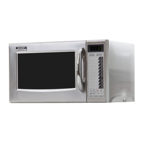
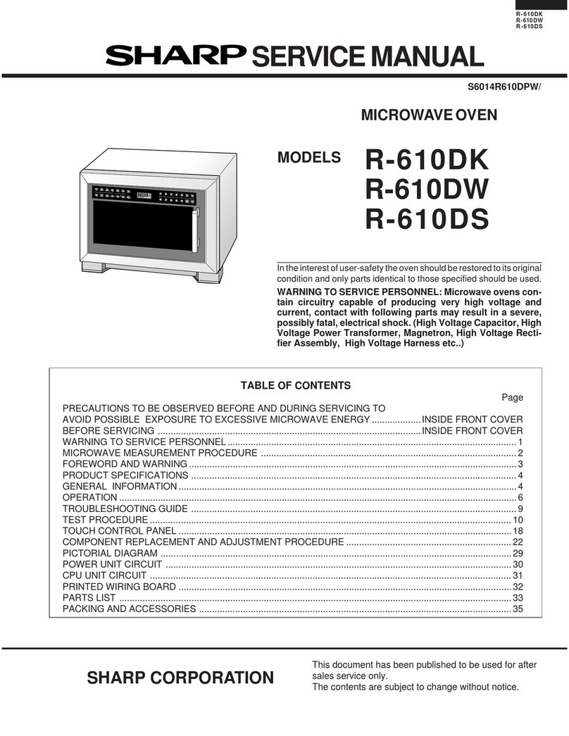
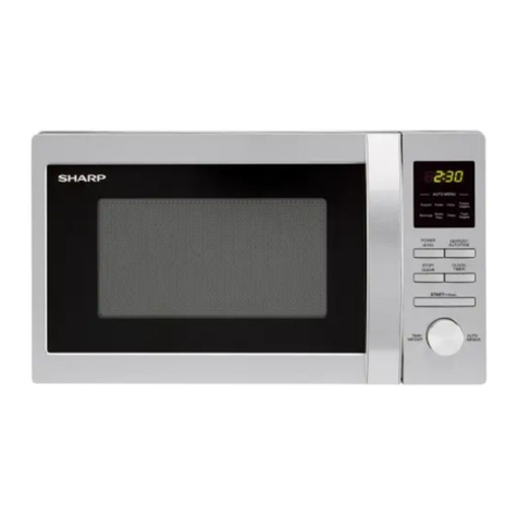
Sharp R-7H55 User manual

R-7H55
SHARP CORPORATION
SERVICE MANUAL
In interests of user-safety the oven should be restored to its original
condition and only parts identical to those specified should be used.
TABLE OF CONTENTS
CONVECTION
MICROWAVE OVEN
MODEL R-7H55
Page
CAUTION, MICROWAVE RADIATION................................................................................................................. 1
WARNING..............................................................................................................................................................1
PRODUCT SPECIFICATIONS ............................................................................................................................. 2
APPEARANCE VIEW ........................................................................................................................................... 3
OPERATION SEQUENCE.................................................................................................................................... 4
FUNCTION OF IMPORTANT COMPONENTS .................................................................................................... 7
SERVICING .......................................................................................................................................................... 9
TEST PROCEDURE ........................................................................................................................................... 12
TOUCH CONTROL PANEL .................................................................................................................................20
COMPONENT REPLACEMENT AND ADJUSTMENT PROCEDURE ............................................................... 26
MICROWAVE MEASUREMENT ........................................................................................................................ 32
WIRING DIAGRAM ............................................................................................................................................. 33
PICTORIAL DIAGRAM ....................................................................................................................................... 35
CONTROL PANEL CIRCUIT ...............................................................................................................................36
PRINTED WIRING BOARD .................................................................................................................................37
PARTS LIST ....................................................................................................................................................... 38
S6417R7H55PHR

R-7H55

R-7H55
1
SERVICE MANUAL
PRODUCT SPECIFICATIONS
CAUTION
MICROWAVE RADIATION
Serviceengineersshouldnotbeexposedtothemicrowave
energy which may radiate from the magnetron or other
microwave generating devices if it is improperly used or
connected. All input and output microwave connections,
waveguides, flanges and gaskets must be secured. Never
operate the device without a microwave energy absorbing
load attached. Never look into an open waveguide or
antenna while the device is energized.
SHARP CORPORATION
OSAKA, JAPAN
WARNING
Never operate the oven until the following points are ensured.
(A) The door is tightly closed.
(B) The door brackets and hinges are not defective.
(C) The door packing is not damaged.
(D) The door is not deformed or warped.
(E) There is not any other visible damage with the oven.
Servicing and repair work must be carried out only by trained
service engineers.
All the parts marked "*" on parts list are used at voltages more
than 250V.
Removal of the outer wrap gives access to potentials above
250V.
All the parts marked "∆" on parts list may cause undue
microwave exposure, by themselves, or when they are dam-
aged, loosened or removed.
TEST PROCEDURE
SERVICING AND
TROUBLESHOOTING CHART
FUNCTION OF IMPORTANT
COMPONENTS
OPERATING SEQUENCE
APPEARANCE VIEW
MICROWAVE MEASUREMENT
WIRING DIAGRAM
PARTS LIST
TOUCH CONTROL PANEL
ASSEMBLY
COMPONENT REPLACEMENT
AND ADJUSTMENT PROCEDURE
CONVECTION
MICROWAVE OVEN
R-7H55
GENERAL IMPORTANT INFORMATION
ThisManualhasbeenpreparedtoprovideSharpCorp.Service
engineers with Operation and Service Information.
It is recommended that service engineers carefully study the
entire text of this manual, so they will be qualified to render
satisfactory customer service.

2
R-7H55
ITEM DESCRIPTION
Power Requirements 220 Volts
50 Hertz
Single phase
Power Consumption Microwave 1.4 kW
Convection: 1.57 kW
Power Output 850 W nominal of RF microwave energy (IEC 705)
Operating frequency 2450 MHz
Convection heating element 1500 W
Case Dimensions Width 520 mm
Height 305 mm
Depth 464 mm
Cooking Cavity Dimensions Width 348 mm
Height 204 mm
Depth 340 mm
Control Complement Touch Control System
Clock (1:00 - 12:59)
Timer (0 - 99 minutes 99 seconds)
Microwave Power for Variable Cooking
Repetition Rate;
HIGH............. Full power throughout the cooking time
MEDIUM HIGH .............. approx. 70% of FULL Power
MEDIUM ........................ approx. 50% of FULL Power
MEDIUM LOW ............... approx. 30% of FULL Power
LOW............................... approx. 10% of FULL Power
Convection Temperature for Variable Cooking
CONVECTION.................. 40 to 250˚C Temp. control
LOW MIX .......... 180˚C with 10% of microwave power
HIGH MIX ......... 200˚C with 30% of microwave power
GRILL ............................................... 250˚C (Preheat)
SENSOR REHEAT pad, SLOW COOK pad
SENSOR RICE COOK pad
SENSOR STEAM MENU pad
EASY DEFROST pad, AUTO COOK pad
NUMBER and TEMPERATURE pads
MICROWAVE LEVEL pad
MORE, LESS pads
STOP/CLEAR pad
AUTO START/CLOCK pad
INSTANT COOK/START pad
Set Weight (Approx.) 22 kg
PRODUCT SPECIFICATIONS

R-7H55
3
APPEARANCEVIEW
1. Ventilation opening
2. Oven lamp
3. Door hinges
4. Door safety latches
5. See through door
6. Door seals and sealing surfaces
7. Coupling
8. Door open button
9. Touch control panel
1. SENSOR REHEAT PAD
Touch to reheat foods.
2. SLOW COOK PAD
Touch to cook slowly and longer time.
3. RICE COOK PAD
Touch to cook rice, congee or porridge.
4. STEAM MENU PAD
Touch to cook steam menus.
5. AUTO COOK MENUS
6. AUTO COOK PAD
Touch to select Auto Cook mode.
7. CONVECTION COOKING FUNCTION PADS
Press to cook for each function.
8. MICROWAVE LEVEL PAD
Press to select microwave power setting.
It not pressed, HIGH is automatically selected.
9. EASY DEFROST PAD
Press to defrost meat by entering weight..
10.MORE ( ), LESS ( ) PADS
Press to increase / decrease the time in one minute increments
duringcookingortoalterthedonenessfortheMultiCook,Instant
Action or Easy Defrost modes.
11.NUMBER AND TEMPERATURE PADS
Presstoentercookingtimes,clocktime,convectiontemperature
or to select the Auto Cook menus.
12.STOP / CLEAR PAD
Press to clear during programming.
Pressonce tostopoperationofovenduringcooking:presstwice
to cancel cooking programme.
13.AUTO START / CLOCK PAD
Press to select clock or Auto Start time.
14.INSTANT COOK / START PAD
Press once to cook for 1 minute at HIGH or increase by 1 minute
multipleseachtime this padispressedduringcookingcondition.
Press to start oven after setting programmes.
10.Digital read-out
11.Wave guide cover
12.Convection air opening
13.Power supply cord
14.Rating label
15.Low lack
16.High lack
17.Earth wire
SLOW
COOK RICE
COOK STEAM
MENU
1 High
2 Low 1 Rice
2 Congee
3 Porridge
1 Fish
2 Meat
3 Dumpling
1 Roast Chicken
2 Steak
3 Noodles
4 Jacket Potato
5 Reheat Beverage
6 Reheat Bread
AUTO COOK
GRILL
MICROWAV
E LEVEL
LESS MORE
12345
67890
STOP
CLEAR INSTANT COOK
START
AUTO
START
CLOCK
2
5
7
8
12
11
13
14
10
6
4
3
FUZZY
SENSOR
REHEAT 1
EASY
DEFROST
CONVEC
HIGH
MIX
LOW
MIX
9
40˚C 70˚C 130˚C 150˚C 160˚C
180˚C 200˚C 220˚C 230˚C 250˚C
TOUCH CONTROL PANEL
CONV
AUTO
SENSOR
REHEAT
MIX GRILL MED LOW HIGH
COOK DEFROST Kg
Indicators
3
47
11
8
10
9
52415 16
12
13
6
1
14
17

4
R-7H55
OPERATING SEQUENCE
OFF CONDITION
Closing the door activates all door interlock switches
(1st latch switch, 2nd latch switch and stop switch).
IMPORTANT
When the oven door is closed, the monitor switch contacts
COM-NC must be open.
When the microwave oven is plugged in a wall outlet, rated
voltage is supplied to the point A1+A3 in the control unit.
Figure O-1 on page 33
1. The display flashes “88:88”.
2. To set any programmes or set the clock, you must first
touch the STOP/CLEAR key.
3. “ : “appearsinthedisplayandthetimecountsupevery
minute.
NOTE: When the oven door is opened, the oven lamp
comes on at this time.
MICROWAVE COOKING CONDITION
HIGH COOKING
Enter a desired cooking time with the touching NUMBER
key and start the oven with touching START key.
Function sequence Figure O-2 on page 33
CONNECTED COMPONENTS RELAY
Oven lamp, Turntable motor (Power transformer) RY1
Power transformer RY2
Fan motor RY4
1. Rated voltage is supplied to the primary winding of the
powertransformer.Thevoltageisconvertedtoabout3.3
volts A.C. output on the filament winding and high
voltageof approximately 2000voltsA.C.onthesecond-
ary winding.
2. The filament winding voltage (3.3 volts) heats the mag-
netron filament and the high voltage (2000 volts) is sent
to the voltage doubling circuit, where it is doubled to
negative voltage of approximately 4000 volts D.C..
3. The2450 MHz microwave energy producedin the mag-
netrongeneratesawavelengthof12.24cm.Thisenergy
ischannelledthroughthewaveguide(transportchannel)
into the oven cavity, where the food is placed to be
cooked.
4. When the cooking time is up, a signal tone is heard and
the relays (RY1+RY2+RY4) go back to their home
position. The circuits to the oven lamp, power trans-
former, fan motor and turntable motor are cut off.
5. When the door is opened during a cook cycle, the
switches come to the following condition.
Condition
During Oven Door
Switch Contact Cooking Open(No cooking)
1st Latch Switch COM-NO Closed Open
Monitor Switch COM-NC Open Closed
2nd Latch Switch COM-NO Closed Open
Stop Switch COM-NO Closed Open
The circuits to the power transformer and turntable
motorarecut off when the 1stlatchswitch and 2nd latch
switchare made open.The fan motor is cutoff when the
stop switch is made open.
The oven lamp remains on even if the oven door is
opened after the cooking cycle has been interrupted,
because the relay (RY1) stays closed. Shown in the
display is the remaining time.
6. MONITOR SWITCH CIRCUIT
The monitor switch is mechanically controlled by
oven door, and monitors the operation of the 1st latch
switch and 2nd latch switch.
6-1 Whentheovendoorisopenedduringor after the cycle
of a cooking program, the contacts (COM-NC) of the
monitorswitchmustbeclosed andthecontacts(COM-
NO) of the 1st latch switch, 2nd latch switch and stop
switch must be opened at the same time.
6-2. Whentheovendoor isclosed, thecontacts (COM-NC)
ofthemonitorswitchmustbeopened andthecontacts
(COM-NO)ofthe1stlatchswitch,2ndlatchswitchand
stop switch must be closed at the same time.
6-3. Whentheovendoorisopenedandthecontacts(COM-
NO) of the 1st latch switch and the 2nd latch switch
remain closed and relay RY2 closes, the fuse M8A will
blow, because the contacts (COM-NC) of the monitor
switch and relay RY1 are closed and a short circuit is
caused.
MEDIUM HIGH, MEDIUM, MEDIUM LOW, LOW COOKING
When the microwave oven is preset for variable cooking
power, rated voltage is supplied to the power transformer
intermittently within a 32-second time base through the
relaycontactwhichiscoupledwiththecurrent-limitingrelay
RY2. The following levels of microwave power are given.
SETTING
NOTE: TheON/OFFtimeratiodoesnotexactlycorrespond
to the percentage of microwave power, because
approx. 2 seconds are needed for heating up the
magnetron filament.
CONVECTION COOKING CONDITION
PREHEATING CONDITION
Program desired convection temperature by touching the
CONVECTION pad and the temp. pad. When the START
pad is touched, the following operations occur:
1. The coil of shut-off relays RY1+RY5+RY4 are ener-
gized,theovenlamp, cooling fan motor, turntablemotor
and convection motor are turned on.
32 sec. ON
24 sec. ON
18 sec. ON
12 sec. ON
6 sec. ON
8 sec. OFF
14 sec. OFF
20 sec. OFF
26 sec. OFF
HIGH
MEDIUM HIGH
MEDIUM
MEDIUM LOW
LOW
Approx. 70%
Approx. 50%
Approx. 30%
Approx. 10%

R-7H55
5
2. Thecoilofrelay(RY6)isenergizedbytheCPUunit.The
damper is moved to the closed position, opening the
damper switch contacts. The opening of the damper
switchcontactssendsasignaltotheLSIontheCPUunit
de-energizing the relay (RY6) and opening the circuit to
the damper motor.
3. The coil of heater relay (RY3) is energized by the CPU
unitandthe main supplyvoltageisaddedtotheconvec-
tion heater.
4. Whentheoventemperaturereachestheselectedpreheat
temperature, the following operations occur:
4-1. Theheaterrelay(RY3)isde-energizedbytheCPUunit
temperature circuit and thermistor, opening the circuit
to the convection heater.
4-2. The oven will continue to function for 30 minutes,
turning the convection heater on and off, as needed to
maintain the selected preheat temperature. The oven
will shut-down completely after 30 minutes.
CONVECTION COOKING CONDITION
Whenthepreheattemperatureisreached,abeepsignalwill
sound indicating that the holding temperature has been
reached in the oven cavity. Open the door and place the
food to be cooked in the oven. Program desired cooking
time and convection temperature by touching the number
pad, CONVECTION pad and Temperature pad. When the
START pad is touched, the following operations occur:
1. The numbers of the digital readout start the count down
to zero.
2. The oven lamp, turntable motor, cooling fan motor and
convection motor are energized.
3. Heater relay (RY3) is energized (if the cavity tempera-
tureislowerthantheselectedtemperature)andthemain
supply voltage is applied to the convection heater to
return to the selected cooking temperature.
4. Upon completion of the cooking time, the audible signal
will sound, and oven lamp, turntable motor, cooling fan
motor and convection motor are de-energized. At the
end of the convection cycle, if the cavity air temperature
isabove118˚C,thecircuitto(RY4)willbemaintained(by
thethermistorcircuit)tocontinueoperationofthecooling
fan motor until the temperature drops below 118˚C, at
which time the relay will be de-energized, turning off the
fan motor. Relay (RY5) will however, open as soon as
the convection cycle has ended, turning off the convec-
tion fan motor. This will now cool and allow the damper
door to open.
5. At the end of the convection cook cycle, shut-off relay
(RY6) is energized turning on the damper motor. The
damper is returned to the open position, closing the
damper switch contacts which send a signal to the
control unit, de-energizing shut-off relay (RY6).
MIX COOKING CONDITION
Program desired cooking time and the LOW MIX or HIGH
MIXandtemperature.WhentheSTARTpadistouched,the
following operations occur:
1. The numbers of the digital readout start the count down
to zero.
2. The shut-off relay (RY1+RY5+RY4) energized, turning
ontheovenlamp,turntablemotor,coolingfanmotorand
convection motor.
3. The shut-off relay (RY6) is energized.
The damper door is closed from the open position.
4. The heater relay (RY3) is energized, adding the mains
supply voltage to the convection heater.
5. Now, the oven is in the convection cooking condition.
6. When the oven temperature reaches the selected tem-
perature, the following operations occur:
6-1. The power supply voltage is added to the convection
heater and power transformer alternately.
6-2. The convection heater operates through the heater
relay (RY3) contacts and the power transformer oper-
ates through the cook relay (RY2) contacts.
6-3. These are operated by the CPU unit to supply alter-
nately within a 32 second time base, convection heat
and microwave energy.
The relationship between the convection and micro-
wave power operations are as follows.
Note: The ON and OFF time ratio does not correspond
with the percentage of microwave power, because
approx. 2 seconds are needed for heating of the
magnetron filament.
EASY DEFROST COOKING
TheEASYDEFROSTkeyisaspecialfunctionkeytodefrost
meats and poultry faster and better. EASY DEFROST
automatically defrosts roast beef, etc.. When the EASY
DEFROST is selected and the food weight is entered by
using the number pads, the oven will cook according to the
special cooking sequence.
AUTO COOK CONDITION
AUTOCOOKwillautomaticallycomputetheoventempera-
ture, microwave power and cooking time for baking, roast-
ingandbroiling.Itisbasedonspecificfoodsandthequantity
or weight of the food. Program the AUTO COOK mode by
touchingtheAUTOCOOKpadandNumberpads,enterthe
weight of the food by touching the Number pads. When the
START pad is touched, the oven will generate the micro-
waveenergy and/or convection heater energy according to
the programmed special cooking sequence.
12 SEC. 20 SEC.
32 SEC.
LOW MIX
HIGH MIX
MICROWAVE POWER
= APPROX. 30%
CONVECTION
TEMPERATURE
= 200˚C
MICROWAVE POWER
= APPROX. 10%
CONVECTION
TEMPERATURE
= 180˚C
26 SEC.6 SEC.
ON
ON
OFF
OFF
OFF
ON
(MICRO.)
(CONVEC.)
(MICRO.)
(CONVEC.)
Note: During alternate Microwave/Convection operation,
the convection heater is energized only if the cavity
temperature drops below the set temperature.
6
R-7H55
SENSOR COOKING CONDITION
Using the SENSOR REHEAT, SENSOR RICE COOK or
SENSOR STEAM MENU function, the foods are cooked or
defrosted without figuring time, power level or quantity.
When the oven senses enough steam from the food, it
relaystheinformationtoitsmicroprocessorwhichwillcalcu-
latethe remaining cookingtime and powerlevel needed for
best results.
When the food is cooked, water vapor is developed. The
sensor "senses" the vapor and its resistance increases
gradually. When the resistance reaches the value set ac-
cording to the menu, supplementary cooking is started.
Thetimeofsupplementarycookingisdeterminedbyexperi-
ment with each food category and inputted into the LSI.
An example of how sensor works: (BAKED POTATOES)
Theshut-offrelaysandcookrelayarede-energizedand
the power transformer, oven lamp, etc. are turned off.
6. OpeningthedoorortouchingtheSTOP/CLEARpad,the
timeofdaywillreappearonthedisplayandtheovenwill
revert to an OFF condition.
FIRE SENSING FEATURE (MICROWAVE MODE)
This model incorporates a sensing feature which will stop
theoven'soperationifthereisafireintheovencavityduring
microwave cooking.
This accomplished by the LSI repeatedly measures the
voltage across the temperature measurement circuit (ther-
mistor) during it's 32-seconds time base comparing the
obtainedvoltagemeasurements.Ifthemostrecent voltage
measuredis300mVgraterthanthepreviousvoltagemeas-
ured, the LSI judges it as a fire in the oven cavity and
switches off the relays to the power transformer, fan motor
and convection motor. The LSI also stops counting down
andclosesthedamperdoorsothatnofreshairwillenterthe
oven cavity. Please refer to the following section for a more
detailed description.
Operation
Please refer to the timing diagrams below.
1. The thermistor operates within a 32-seconds time base
and it is energized for three (3) seconds and off for 29
seconds. Two (2) seconds after the thermistor is ener-
gized,thevoltageacrossthetemperaturemeasurement
circuit is sampled by the LSI and twenty one (21) sec-
onds after the thermistor is cut off the LSI turns on the
cooling fan for six (6) seconds.
2. The above procedure is repeated. If the difference
between the first voltage measured (in step 1) and the
voltagemeasuredwhentheprocedureisrepeated(step
2) is greater than 300mV the LSI makes the judgment
thatthereisafireintheovencavityandwillswitchoffthe
relays to the power transformer, fan motor and convec-
tionmotor.TheLSIalsostopscountingdownandcloses
the damper door so that no fresh air will enter the oven
cavity.
3. Once the fire sensor feature has shut the unit down, the
programmed cooking cycle may be resumed by press-
ingthe"START"padortheunitmayberesetbypressing
the "CLEAR" pad.
CONVECTION
MOTOR
THERMISTOR
Sensing
Voltage
ON
OFF
ON
OFF
ON
OFF
0 2 24 30 64 (sec.)
3 sec.
Sensing the voltage across the temperature measurement circuit.
6 sec.
332 (sec.)
IMPORTANT:
During sensor cooking operation, the fire sensing op-
erationsequence will notbegin until theAHsensor has
detected vapours and initiated a sensor cooking cycle.
This is because the operation of the convection fan
would interfere with the AH sensor's vapour detection.
MICROWAVE
MICROWAVE
AH SENSOR
1. Potatoesatroomtempera-
ture. Vapor is emitted very
slowly.
2. Heat potatoes. Moisture
andhumidityisemittedrap-
idly. You can smell the
aroma as it cooks.
3. Sensor detects moisture
and humidity and calcu-
latescookingtimeandvari-
able power.
Cooking Sequence.
1. Touch SENSOR REHEAT, SENSOR RICE COOK or
SENSOR STEAM MENU pad.
NOTE:The oven should not be operated on SENSOR
REHEAT, SENSOR RICE COOK or SENSOR
STEAM MENU immediately after plugging in the
unit. Wait five minutes before cooking on SENSOR
REHEAT, SENSOR RICE COOK or SENSOR
STEAM MENU.
2. The coils of shut-off relays (RY-1 and RY-4) are ener-
gized, the turntable motor, oven lamp and cooling fan
motor are turned on, but the power transformer is not
turned on.
3. After about 16 seconds, the cook relay (RY-2) is ener-
gized. The power transformer is turned on, microwave
energy is produced and first stage is started.
The 16 seconds is the cooling time required to remove
any vapor from the oven cavity and sensor.
NOTE: Duringthisfirststage,donotopenthedoorortouch
STOP/CLEAR pad.
4. When the sensor detects the vapor emitted from the
food,thedisplay switches overtotheremainingcooking
time and the timer counts down to zero.
At this time, the door may be opened to stir food, turn it
or season, etc.
5. Whenthe timer reaches zero, anaudible signal sounds.

R-7H55
7
FUNCTION OF IMPORTANT COMPONENTS
DOOR OPEN MECHANISM
The door is opened by
pushingtheopenbuttonon
the control panel, refer to
the Figure D-1.
When the open button is
pushed, the open button
pushesuptheswitchlever,
and then the switch lever
pushes up the latch head.
Thelatchheadsaremoved
upward and released from
latch hook. Now the door
will open.
Figure D-1. Door Open Mechanism
1ST. LATCH SWITCH, 2ND. LATCH SWITCH AND
STOP SWITCH
1. When the oven door is closed, the contacts COM-NO)
must be closed.
2. Whentheovendoorisopened,thecontacts.(COM-NO)
must be opened.
MONITOR SWITCH
1. When the oven door is closed, the contacts (COM-NC)
must be opened.
2. When the oven door is opened, the contacts (COM-NC)
must be closed.
3. If the oven door is opened and the contacts (COM-NO)
of the 1st. latch switch, 2nd. latch switch and relay RY2
fail to open, the fuse M8A blows simultaneously with
closing the contacts (COM-NC) of the monitor switch.
CAUTION: BEFORE REPLACING A BLOWN FUSE M8A
TESTTHE1ST.LATCHSWITCH,2ND.LATCH
SWITCH MONITOR SWITCH, RELAYS (RY1
AND RY-2) AND MONITOR RESISTOR FOR
PROPER OPERATION.
MONITOR RESISTOR R 0.8Ω20W
The monitor resistor prevents the fuse M8A bursting when
the fuse M8A blows due to the operation of the monitor
switch.
ASYMMETRIC RECTIFIER
Theasymmetricrectifierisasolidstatedevicethatprevents
currentflow in bothdirections. And it prevents thetempera-
ture rise of the power transformer by blowing the fuse M8A
when the high voltage rectifier is shorted.
The rated peak reverse voltage of D1 of the asymmetric
rectifier is 6 KV The rated peak reverse voltage of D2 of the
asymmetricrectifieris1.7KV.D1andD2oftheasymmetric
rectifier or high voltage rectifier are shorted when the each
peak reverse voltage goes beyond the each rated peak
reverse voltage. (The process of blowing the fuse M8A.)
1. Thehigh voltagerectifierisshortedbyanycauseswhen
microwave cooking.
2. The peak reverse voltage of D2 of the rectifier goes
beyond the rated peak reverse voltage 1.7 KV in the
voltage doubler circuit.
3. D2 of the rectifier is shorted.
4. The large electric currents flow through the high voltage
winding of the power transformer.
5. ThelargeelectriccurrentsbeyondM8Aflowthroughthe
primary winding of the power transformer.
6. The fuse M8A blows by the large electric currents.
7. The power supply to the all electrical parts are cut off.
FUSE M8A
1. ThefuseM8Ablowswhenthecontacts(COM-NO)ofthe
1st. latch switch 2nd. latch switch and relay RY2 remain
closed with the oven door open and when the monitor
switch closes.
2. The fuse M8A also blows when asymmetric rectifier,
H.V. rectifier, H.V. wire harness, H.V. capacitor, magn-
etron or secondary winding of power transformer is
shorted.
3. If the wire harness or electrical components are short-
circuited, this fuse M8A blows to prevent an electric
shock or fire hazard.
THERMAL CUT-OUT 145˚C (MG)
This thermal cut-out protects the magnetron against over-
heating. If the temperature goes up higher than 145˚C
because the fan motor is interrupted, the ventilation open-
ings are blocked, the thermal cut-out will open and the line
voltage to the power transformer will be cut off and the
operation of the magnetron will be stopped.
The defective thermal cut-out must be replaced with new
one.
THERMAL CUT-OUT 150˚C (CONVECTION)
The thermal cut-out protect the convection motor against
overheating.Ifitstemperatureoftheconvectionmotor rises
above 150˚C because the convection fan motor is inter-
rupted, the ventilation openings are obstructed or the other
abnormal matter occurs, the thermal cut-out opens and
switch of the oven. When thermal cut-out cools itself down
to130˚C,thecontactsofthethermalcut-outwillcloseagain.
THERMAL CUT-OUT 95˚C (FAN MOTOR)
Thethermalcut-out protect the fan motoragainstoverheat-
ing.Ifitstemperaturegoesuphigherthan95˚Cbecausethe
fanmotor is locked orthe ventilation operatingare blocked,
the contacts of the thermal cut-out will open and switch off
the oven. When the oven cools itself down to 75˚C, the
contacts of the thermal cut-out will close again.
LATCH
HEADS
LATCH HOOK
2ND. LATCH
SWITCH
MONITOR
SWITCH
SWITCH
LEVER
STOP SWITCH
1ST. LATCH
SWITCH
D2 D1
ASYMMETRIC
RECTIFIER
HIGH VOLTAGE RECTIFIER
AB
C

8
R-7H55
THERMISTOR
The thermistor is a negative temperature coefficient type.
The temperature in the oven cavity is detected through the
resistanceofthe thermistor, andthenthecontrolunitcause
theheatingelement relay to operate, thusthecurrent to the
heating element is turned ON/OFF.
TURNTABLE MOTOR
The turntable motor drives the turntable roller assembly to
rotate the turntable.
CONVECTION MOTOR
The convection motor drives the convection fan and pro-
vides the heated air.
FAN MOTOR
The fan motor drives a blade which draws external cool air.
This cool air is directed through the air vanes surrounding
the magnetron and cools the magnetron. This air is chan-
nelled through the oven cavity to remove steam and va-
pours given off from the heating foods. It is then exhausted
through the exhausting air vents at the oven cavity
HEATING ELEMENT
The heating element is located at the rear side of the oven
cavity.Itisintendedto heatairdrivenbytheconvectionfan.
The heated air is kept in the oven and force-circulated and
reheated by the heating element.
CONVECTION COOKING SYSTEM
This oven is designed with a hot air heating system where
food is not directly heated by the heating element, but is
heated by forced circulation of the hot air produced by the
heating element.
The air heated by the heating element is circulated through
theconvection passage providedon the outercasing of the
oven cavity by means of the convection fan which is driven
bytheconvectionmotor.Itthenenterstheinsideoftheoven
throughtheventholesprovidedontherearsideoftheoven.
Next, the hot air heats the food on the turntable and leaves
the oven cavity through the vent in the center of the oven
cavity rear side wall.
Without leaving the oven, this hot air is reheated by the
heating element, passes through the convection passage
and enters the inside of the oven cavity again, in a continu-
ing cycle.
In this way, the hot air circulates inside the oven cavity to
raise its temperature and, at the same time, comes into
contact with the food being cooked.
When the temperature inside the oven cavity reaches the
selectedtemperature,theheatingelementisde-energized.
When the temperature inside the oven cavity drops below
theselectedtemperature,the heating element is energized
again.Inthisway,theinsideoftheovencavityismaintained
at approximately the selected temperature.
Whentheconvectiontimereaches0,theheatingelementis
de-energized and the convection fan stops operating and
the oven shuts off.
DAMPER OPEN-CLOSE MECHANISM
Usually, the damper is in the open position except during
convection cooking.
Damper position is set automatically by damper motor,
damper switch, damper cam and damper shaft.
These components are operated by a signal that judges if
microwave cooking or convection cooking operation is
selected by the control unit.
Microwave Cooking:
Damperisintheopenposition,becauseaportionofcooling
air is channeled through the cavity to remove steam and
vapors given off from the heating foods
It is then exhausted at the top of the oven cavity into a
condensation compartment.
Convection Cooking:
Damper is in the closed position, so that no hot air will be
allowed to leak out the oven cavity.
Damper Operation
1-1. When power supply cord is plugged in, a signal is
sensed in the control unit, and operates shut-off relay
(RY6).
1-2. Contacts of shut-off relay (RY6) close, the damper
motor is energized, opening the damper door.
1-3. When thedamper is movedto the openposition by the
dampercamthedamperswitchisclosed(ONposition).
1-4. The signalof damper switchis re-sensedin thecontrol
unit and shut-off relay (RY6) is turned off.
1-5. The A.C.line voltage to the damper motor is removed
and the motor turns off.
2. When oven is microwave cooking:
Damper is in the open position.
3. When oven is convection cooking:
3-1. Dampermotorisenergizedbytouchingtheconvection,
temperature and START pads.
3-2. When damper is in the closed position (damper switch
is OFF), its signal is sensed by the control unit, and
shut-off relay (RY6) is de-energized.
3-3. The damper is held in the closed position during the
convection cooking operation.
3-4. At the end of the convection cooking, shut-off relay
(RY6) is energized, and the damper is returned to the
open position.
NOTE: If the damper door is not in the proper position,
closedduringconvectionoropenduringmicrowave,
the control unit will stop oven operation after 1
minute.
Figure D-2. Damper Mechanism
DAMPER CAM DAMPER SWITCH
DAMPER SHAFT
DAMPER DUCT
CUSHION
DAMPER MOTOR DAMPER PLATE

R-7H55
9
TROUBLESHOOTING GUIDE
When troubleshooting the microwave oven, it is helpful to
follow the Sequence of Operation in performing the
checks. Many of the possible causes of trouble will require
that a specific test be performed. These tests are given a
procedure letter which will be found in the "Test
Procedure"section.
IMPORTANT: Iftheovenbecomesinoperativebecauseof
a blown fuse M8A in the 1st. latch switch -
2nd. latch switch - relay RY1 - relay RY2 -
monitor switch - monitor resistor circuit,
checkthe1st.latchswitch,2nd.latchswitch,
monitor switch relay RY1, relay RY2 and
monitor resistor before replacing the fuse
M8A.
SERVICING
WARNING TO SERVICE PERSONNEL
Microwave ovens contain circuitry capable of producing very high voltage and current, contact with any part of the
high voltage circuit will result in electrocution. High voltage capacitor, Power transformer, Magnetron, High voltage
rectifier assembly, High voltage harness.
REMEMBER TO CHECK 3D
1) Disconnect the supply.
2) Door opened, and wedged open.
3) Discharge high voltage capacitor.
WARNING: AGAINST THE CHARGE OF THE
HIGH-VOLTAGE CAPACITOR
The high-voltage capacitor remains charged about
60 seconds after the oven has been switched off.
Wait for 60 seconds and then short-circuit the con-
nection of the high-voltage capacitor (that is, of the
connectingleadofthehigh-voltagerectifier)against
thechassiswiththeuseofaninsulatedscrewdriver.
Sharp recommend that wherever possible fault-finding
is carried out with the supply disconnected. It may in,
some cases, be necessary to connect the supply after
theouter case hasbeenremoved,inthisevent carry out
3D checks and then disconnect the leads to the primary
of the power transformer. Ensure that these leads re-
main isolated from other components and the oven
chassis. (Use insulation tape if necessary.) When the
testing is completed carry out 3D checks and reconnect
the leads to the primary of the power transformer.
Whenallserviceworkiscompleted,andtheovenisfullyassembled,themicrowavepoweroutputshouldbechecked
and microwave leakage test carried out
REMEMBER TO CHECK 4R
1) Reconnect all leads removed from components dur-
ing testing.
2) Replace the outer case (cabinet).
3) Reconnect the supply.
4) Run the oven. Check all functions.
Microwave ovens should not be run empty. To test for
thepresenceofmicrowaveenergy within a cavity, place
acup of coldwater on theoven turntable, closethe door
andset the microwavetimerfortwo(2)minutes. Setthe
powerlevelto HIGH and push theSTARTbutton. When
the two minutes has elapsed (timer at zero) carefully
checkthatthewaterisnowhot.Ifthewaterremainscold
carry out 3D checks and re-examine the connections to
the component being tested.
NOISE FILTER
The noise filter prevents the radio frequency interference that might flow back in the power circuit.

10
R-7H55
OFF
CONDITION
PROBLEM
CONDITION
CK = Check / RE = Replace
COOKING
CONDITION
(COMMON)
COOKING
CONDITION
(MICROWAVE)
COOKING
CONDITION
(
CONVECTION
)
POSSIBLE CAUSE
AND
DEFECTIVE PARTS
TEST PROCEDURE
SENSOR
COOKING
CONDITION
Home fuse blows when power supply cord
is plugged into wall outlet.
Fuse M8A blows when the door is opened.
FUSE M8A blows when power supply cord
is plugged into wall outlet.
"88:88" does not appear in display when
power supply cord is first plugged into wall
outlet.
Display does not operate properly when
STOP/CLEAR pad is touched. (The time of
day should be appear on the display with
beep sound during normal condition.)
Oven lamp does not light at door opened.
Oven lamp does not light at all.
Turntable motor does not operate. (Oven
lamp light.)
Cooling fan motor does not operate.
The oven stops after 1 minute.
Oven does not go into cook cycle, when
START pad is touched.
Low or no power is produced during micro-
wave cooking (The food is heated incom-
pletely or not heated at all)
Extremely uneven heating is produced in
oven load (food).
Functionofvariable cooking does not oper-
ate properly except HIGH power.
CONV indicator lights, but heating element
does not heat.
Temperature in the oven cavity is lower or
higher than preset.
When preheating, the oven does not stop.
Convection cycle runs 4 minutes and 15
seconds then the oven shuts down.
AH sensor does not end during Sensor
Cooking condition.(Oven does not shut off
when a cup of water is boiling by Sensor
Cooking.)
Oven stops at 16 sec. after starting
MAGNETRON
POWER TRANSFORMER
H.V. RECTIFIER ASSEMBLY
HIGH VOLTAGE CAPACITOR
1ST. LATCH SWITCH
2ND. LATCH SWITCH
STOP SWITCH
MONITOR SWITCH
FUSE M8A
THERMAL CUT-OUT 145˚C (MG.)
THERMAL CUT-OUT 95˚C (FAN)
THERMAL CUT-OUT 150˚C (CONV.)
FAN MOTOR
TURNTABLE MOTOR
CONVECTION MOTOR
CONVECTION HEATER
THERMISTOR
ABC
D
EEEEF GGGHHH I J

R-7H55
11
HERE
L
M N N N N N N CKRERECK K P CK O
DAMPER MOTOR
DAMPER SWITCH
OVEN LAMP OR SOCKET
TOUCH CONTROL PANEL
KEY UNIT
RELAY (RY-1)
RELAY (RY-2)
RELAY (RY-3)
RELAY (RY-4)
RELAY (RY-5)
RELAY (RY-6)
OPENED WIRE HARNESS
SHORTED WIRE HARNESS
POWER SUPPLY CORD
NO POWER AT WALL OUTLETT
MONITOR SESISTOR
FOIL PATERN ON PWB.
OPEN WIRING TO THERMISTOR
AH SENSOR ASSEMBLY
NOISE FILTER
Q

12
R-7H55
TEST PROCEDURES
PROCEDURE
LETTER
CARRY OUT 3D CHECK
Isolate the magnetron from high voltage circuit by removing all leads connected to filament terminal.
To test for an open circuit filament use an ohmmeter to make a continuity test between the magnetron
filament terminals, the meter should show a reading of less than 1 ohm.
To test for short filament to anode condition, connect ohmmeter between one of the filament terminals
and the case of the magnetron (ground). This test should be indicated an infinite resistance. If a low or
zero resistance reading is obtained then the magnetron should be replaced.
MICROWAVE OUTPUT POWER (1 Litre water load)
The following test procedure should be carried out with the microwave oven in a fully assembled
condition (outer case fitted). Microwave output power from the magnetron can be measured by way of
IEC 705, i.e. it can be measured by using water load how much it can be absorbed by the water load.
Tomeasurethe microwave output power inthemicrowaveoven,therelationofcalorieandwattis used.
When P(W) heating works for t(second), approximately P x t/4.187 calorie is generated. On the other
hand, if the temperature of the water with V(ml) rises∆T (°C) during this microwave heating period, the
calorie of the water is V x ∆T.
NEVER TOUCH ANY PART IN THE CIRCUIT WITH YOUR HAND OR AN INSULATED TOOL
WHILE THE OVEN IS IN OPERATION.
AMAGNETRON TEST
The formula is as follows;
P x t / 4.187 = V x ∆T P (W) = 4.187 x V x ∆T / t
Our condition for water load is as follows:
Room temperature..............around 20°C PowersupplyVoltage.........Ratedvoltage
Water load.........1000 g Initial temperature...........10±2°C Heating time.........49 sec.
P = 85 x ∆T
Measuring condition:
1. Container
The water container must be a cylindrical borosilicate glass vessel having a maximum material
thickness of 3 mm and an outside diameter of approximately 190 mm.
2. Temperature of the oven and vessel
The oven and the empty vessel are at ambient temperature prior to the start the test.
3. Temperature of the water
The initial temperature of the water is (10±2)°C.
4. Selecttheinitial and finalwater temperature so thatthe maximum difference betweenthe final water
temperature and the ambient temperature is 5K.
5. Select stirring devices and measuring instruments in order to minimize addition or removal of heat.
6. Thegraduationof the thermometermustbescaledby0.1°Catminimumandaccuratethermometer.
7. The water load must be (1000±5) g.
8. “t” is measured while the microwave generator is operating at full power. Magnetron filament heat-
up time is not included.
NOTE:The operation time of the microwave oven is “t + 2” sec. 2 sec. is magnetron filament heat-up time.
Measuring method:
1. Measure the initial temperature of the water before the water is added to the vessel.
(Example: The initial temperature T1 = 11°C)
2. Add the 1 litre water to the vessel.
3. Place the load on the centre of the shelf.
4. Operate the microwave oven at HIGH for the temperature of the water rises by a value ∆T of
(10 ±2) K.
5. Stir the water to equalize temperature throughout the vessel.
COMPONENT TEST

R-7H55
13
TEST PROCEDURES
PROCEDURE
LETTER COMPONENT TEST
6. Measure the final water temperature. (Example: The final temperature T2 = 21°C)
7. Calculate the microwave power output P in watts from above formula.
Initial temperature .................................................................................................. T1 = 11°C
Temperature after (49 + 2) = 51 sec. ..................................................................... T2 = 21°C
Temperature difference Cold-Warm.................................................................... ∆T1 = 10°C
Measured output power
The equation is “P = 85 x ∆T” ...................................................... P = 85 x 10°C = 850 Watts
JUDGMENT: The measured output power should be at least ±15 % of the rated output power.
CAUTION: 1°C CORRESPONDS TO 85 WATTS REPEAT MEASUREMENT IF THE POWER IS
INSUFFICIENT.
Heat up for 51 sec.
1000g
1000g
1000g
T1˚C T2˚C
B POWER TRANSFORMER TEST
WARNING: Highvoltagesandlargecurrentsarepresentatthesecondarywindingandfilament
winding transformer. It is very dangerous to work near this part when the oven is
on.NEVERmakeanyvoltagemeasurementsofthehigh-voltagecircuits,including
the magnetron filament.
CARRY OUT 3D CHECKS
Disconnect the leads to the primary winding of the power transformer. Disconnect the filament and
secondarywindingconnectionsfromtherestoftheHVcircuitry.Usinganohmmeter,setonalowrange,
it is possible to check the continuity of all three windings. The following readings should be obtained:
a. Primary winding ....................approx. 1.2 Ω
b. Secondary winding ...............approx. 92.6 Ω
c. Filament winding...................less than 1 ohm
If the reading obtained are not stated above, then the power transformer is probably faulty and should
be replaced.
CARRY OUT 4R CHECKS
CHIGH VOLTAGE RECTIFIER ASSEMBLY TEST
HIGH VOLTAGE RECTIFIER TEST
CARRY OUT 3D CHECKS.
Isolate the high voltage rectifier assembly from the HV circuit. The high voltage rectifier can be tested
using an ohmmeter set to its highest range. Connect the ohmmeter across the terminal B+C of the high
voltage rectifier and note the reading obtained. Reverse the meter leads and note this second reading.
The normal resistance is infinite in one direction and more than 100 kΩin the other direction.

14
R-7H55
TEST PROCEDURES (CONT'D)
COMPONENT TEST
PROCEDURE
LETTER
CARRY OUT 4R CHECKS
ASYMMETRIC RECTIFIER TEST
CARRY OUT 3D CHECKS.
Isolate the high voltage rectifier assembly from the HV circuit. The asymmetric can be tested using an
ohmmeter set to its highest range across the terminals A+B of the asymmetric rectifier and note the
reading obtained. Reverse the meter leads and note this second reading. If an open circuit is indicated
in both direction then the asymmetric rectifier is good. If an asymmetric rectifier is shorted in either
direction,thentheasymmetricrectifierisprobablyfaultyandmustbereplacedwithhighvoltagerectifier.
Whentheasymmetricrectifierisdefective,checkwhethermagnetron,highvoltagerectifier,highvoltage
wire or filament winding of the power transformer is shorted.
CARRY OUT 4R CHECKS
NOTE: FOR MEASUREMENT OF THE RESISTANCE OF THE RECTIFIER, THE BATTERIES OF THE
MEASURING INSTRUMENT MUST HAVE A VOLTAGE AT LEAST 6 VOLTS, BECAUSE
OTHERWISE AN INFINITE RESISTANCE MIGHT BE SHOWN IN BOTH DIRECTIONS.
AB
C
D2 D1
ASYMMETRIC
RECTIFIER
HIGH VOLTAGE RECTIFIER
D HIGH VOLTAGE CAPACITOR TEST
E SWITCH TEST
Table: Terminal Connection of Switch
Plunger Operation COM to NO COM to NC
Released O.C. S.C.
Depressed S.C. O.C.
COM; Common terminal,
NO; Normally open terminal
NC; Normally close terminal
S.C.; Short,
O.C.; Open circuit
If incorrect readings are obtained, make the necessary switch or replace the switch.
CARRY OUT 4R CHECKS.
Isolate the switch to be tested and using an ohmmeter check between the terminals as described in the
following table.
CARRY OUT 3D CHECKS
CARRY OUT 3D CHECKS
A. Isolate the high voltage capacitor from the circuit.
B. Continuity check must be carried out with measuring instrument which is set to the highest resistance
range.
C. Anormalcapacitorshowscontinuityforashorttime(kick)andthenaresistanceofabout10MΩafterithas
been charged.
D. A short-circuited capacitor shows continuity all the time.
E. An open capacitor constantly shows a resistance about 10 MΩbecause of its internal 10MΩresistance.
F. When the internal wire is opened in the high voltage capacitor shows an infinite resistance.
G. The resistance across all the terminals and the chassis must be infinite when the capacitor is normal.
If incorrect reading are obtained, the high voltage capacitor must be replaced.
CARRY OUT 4R CHECKS
F BLOWN FUSE M8A
CARRY OUT 3D CHECKS
1. If the fuse M8A is blown, there could be shorts or ground in electrical parts or wire harness.
Check them and replace the defective parts or repair the wire harness.
2. If the fuse M8A is blown when the door is opened, check the 1st. latch switch, 2nd. latch switch,
monitor switch, monitor resistor, relay RY1 and relay RY2.
IfthefuseM8Aisblownbyincorrectdoorswitchingreplacethedefectiveswitch(s)andthefuseM8A.

R-7H55
15
TEST PROCEDURES (CONT'D)
PROCEDURE
LETTER COMPONENT TEST
3. Ifthe fuse M8A is blown, there could be a short inthe asymmetricrectifier or there could be a ground
in wire harness. A short in the asymmetric rectifier may have occured due to sh ort or ground in H.V.
rectifier, magnetron, power transformer or H.V. wire. Check them and replace the defective parts or
repair the wire harness.
CARRY OUT 4R CHECKS
CAUTION: Only replace fuse M8A with the correct value replacement.
G THERMAL CUT-OUT TEST
CARRY OUT 3D CHECKS
Disconnect the leads from the terminals of the thermal cut-out. Then using an ohmmeter, make a
continuity test across the two terminals as described in the table below.
CARRY OUT 4R CHECKS
CARRY OUT 3D CHECKS
Disconnect the leads from the motor.
Using an ohmmeter, check the resistance between the two terminals as described in the table below.
H MOTOR WINDING TEST
Table: Resistance of Motor
Motors Resistance
Fan motor Approximately 370 Ω
Turntable motor Approximately 12 kΩ
Convection fan motor Approximately 180 Ω
Damper motor Approximately 11 kΩ
If incorrect readings are obtained, replace the motor.
CARRY OUT 4R CHECKS
Table: Thermal cut-out Test
Temperature of "ON" condition Temperature of "OFF" condition Indication ofohmmeter
Parts Name (closed circuit) (˚C) (open circuit) (˚C) (When room temperature
is approx. 20˚C)
Thermal cut-out 145˚C This is not resetable type Above 145˚C Closed circuit.
Thermal cut-out 150˚C Below130˚C Above 150˚C Closed circuit.
Thermal cut-out 95˚C Below 75˚C Above 95˚C Closed circuit.
If incorrect readings are obtained, replace the thermal cut-out.
An open circuit thermal cut-out 145˚C (MG) indicates that the magnetron has overheated, this may be
dueto resistrictedventilation, coolingfan failureor afault conditionwithin themagnetron orH.V. circuit.
Anopencircuit thermalcut-out150˚C(CONV.)indicatesthattheconvectionmotorhasoverheated,this
may be due to convection motor locked..
Anopencircuitthermalcut-out95˚C(FAN)indicatesthatthefanmotorwindinghasoverheated,thismay
be due to blocked ventilation or locked cooling fan.
ICONVECTION HEATER TEST
CARRY OUT 3D CHECKS
Before carring out the following tests make sure the heater is fully cool.
1. Resistance of heater
Disconnect the wire leads to the heater to be tested. Using ohmmeter with low resistance range.
Check the resistance across the terminals of the heater. The resistance of heater is approximately
32 ohms.

16
R-7H55
TEST PROCEDURES (CONT'D)
PROCEDURE
LETTER COMPONENT TEST
2. Insulation resistance
Disconnect the wire leads to the heater to be tested. Check the insulation resistance between the
element and cavity using a 500V - 100Mohms insulation tester. The insulation resistance should be
more than 10Mohms in the cold start.
If the results of above test 1 and/or 2 are out of above specifications, the heater is probably faulty and
should be replaced.
CARRY OUT 4R CHECKS
CARRY OUT 3D CHECKS
Disconnectconnector-B fromtheCPUunit.Measuretheresistanceofthethermistorwithanohmmeter.
Connect the ohmmeter leads to Pin No’s B-5 and B-6 of the thermistor harness.
Room Temp..........................................20˚C - 30˚C
Resistance..................... Approx. 350 kΩ-- 155 kΩ
If the meter does not indicate above resistance, replace the thermistor.
CARRY OUT 4R CHECKS
JTHERMISTOR TEST
KMONITOR RESISTOR TEST
CARRY OUT 3D CHECKS.
Disconnecttheleadsfromthemonitorresist.Usinganohmmeterandsetonalowrange.Checkbetween
the terminals of the monitor resistor.
The resistance of monitor resistor is approx. 0.8 ohms.
If incorrect readings are obtained, replace the monitor resistor.
CARRY OUT 4R CHECKS.
LTOUCH CONTROL PANEL ASSEMBLY TEST
The touch control panel consists of circuits including semiconductors such as LSI, ICs, etc. Therefore,
unlike conventional microwave ovens, proper maintenance cannot be performed with only a voltmeter
and ohmmeter.
In this service manual, the touch control panel assembly is divided into two units, Control Unit and Key
Unit, and troubleshooting by replacement is described according to the symptoms indicated.
1. Key Unit. Note: Check key unit ribbon connection before replacement.
The following symptoms indicate a defective key unit. Replace the key unit.
a) When touching the pads, a certain pad produces no signal at all.
b) When touching a number pad, two figures or more are displayed.
c) When touching the pads, sometimes a pad produces no signal.
2. Control Panel
Thefollowingsymptoms indicateadefectivecontrolunit. Beforereplacingthecontrolunit,perform
the Key unit test (Procedure M) to determine if control unit is faulty.
2-1 In connection with pads.
a) When touching the pads, a certain group of pads do not produce a signal.
b) When touching the pads, no pads produce a signal.
2-2 In connection with indicators
a) At a certain digit, all or some segments do not light up.
b) At a certain digit, brightness is low.
c) Only one indicator does not light.
d) The corresponding segments of all digits do not light up; or they continue to light up.
e) Wrong figure appears.
f) A certain group of indicators do not light up.
g) The figure of all digits flicker.

R-7H55
17
TEST PROCEDURES (CONT'D)
PROCEDURE
LETTER COMPONENT TEST
2-3 Other possible problems caused by defective control unit.
a) Buzzer does not sound or continues to sound.
b) Clock does not operate properly.
c) Cooking is not possible.
M KEY UNIT TEST
Ifthe display failstoclearwhentheSTOP/CLEAR pad isdepressed,firstverifytheflat ribbon ismarking
goodcontact, verify thatthe door sensingswitch(stop switch) operatesproperly; that isthe contacts are
closed when the door is closed andopen when the door is open. If the door sensing switch(stop switch)
is good, disconnecct the flat ribbon cable that connects the key unit to the control unit and make sure
thedoor sensingswitchisclosed(eitherclose thedoororshortthe doorsensingswitchconnecter).Use
the Key unit matrix indicated on the control panel schematic and place a jamper wire between the pins
that correspond to the STOP/CLEAR pad marking momentary contact. If the control unit responds by
clearing with a beep the key unit is faulty and must be replaced. If the control unit does not respond, it
isafaultyandmustbereplaced. Ifaspecificpaddoesnotrespond,theabovemethodmaybeused(after
clearing the control unit) to determine if the control unit or key pad is at fault.
KEY UNIT
G-1
G-2
G-3G-4G-5G-6G-7
G-8
G-9
G-10
G-11
G-12
5
SLOW
COOK
GRILL
MICRO
WAVE
LEVEL
EASY
DEFROST
AUTO
COOK
MORE
LESS
STOP
CLEAR
INSTANT
COOK
START
LOW
MIX
HIGH
MIX
SENSOR
REHEAT
CONVEC
160˚C
4
150˚C
3
130˚C
2
70˚C
1
40˚C
0
250˚C
9
230˚C
8
220˚C
7
200˚C
6
180˚C
AUTO
START
CLOCK
STEAM
MENU RICE
COOK
CARRY OUT 4R CHECKS
NRELAY TEST
CARRY OUT 3D CHECKS
Remove the outer case and check voltage between Pin Nos. 1 and 3 of the 9 pin connector (A) on the
control unit with an A.C. voltmeter.
The meter should indicat 220 volts, if not check oven circuit.
Relay Test
Check voltage at the relay coil with a D.C. voltmeter during the microwave cooking operation,
convection cooking operation or grill cooking operation.
DC. voltage indicated............................. Defective relay.
DC. voltage not indicated....................... Check diode which is connected to the relay coil. If diode is
good, control unit is defective.
CARRY OUT 4R CHECKS
RELAY SYMBOL OPERATIONAL
VOLTAGE CONNECTED COMPONENTS
RY1 Approx. 26.0V.D.C. Oven lamp/Turntable motor
RY2 Approx. 25.5V.D.C. High voltage transformer
RY3 Approx. 25.0V.D.C. Convection heating element
RY4 Approx. 26.0V.D.C. Fan motor
RY5 Approx. 26.0V.D.C. Convection motor
RY6 Approx. 26.0V.D.C. Damper motor

18
R-7H55
TEST PROCEDURES (CONT'D)
PROCEDURE
LETTER COMPONENT TEST
O PROCEDURES TO BE TAKEN WHEN THE FOIL PATTERN ON THE PRINTED WIRING BOARD
(PWB) IS OPEN
To protect the electronic circuits, this model is provided with a fine foil pattern added to the primary on
thePWB,this foil pattern actsas a fuse. Ifthefoil pattern isopen,follow the troubleshooting guidegiven
below for repair.
Problem: POWER ON, indicator does not light up.
CARRY OUT 3D CHECKS
STEPS OCCURANCE CAUSE OR CORRECTION
1 The rated AC voltage is not present at
POWER terminal of CPU connector (CN-A) Check supply voltage and oven power cord.
2 The rated AC voltage is present at primary
side of low voltage transformer. Low voltage transformer or secondary circuit defective.
Check and repair.
3 Only pattern at "a" is broken. *Insert jumper wire J1 and solder. (CARRY OUT 3D
CHECKS BEFORE REPAIR)
4 Pattern at "a" and "b" are broken. *Insert the coil RCILF2003YAZZ between "c" and "d".
(CARRY OUT 3D CHECKS BEFORE REPAIR)
NOTE: At the time of these repairs, make a visual
inspectionofthevaristor for burning damage
and examine the transformer with tester for
the presence of layer short-circuit (check
primary coil resistance). If any abnormal
condition is detected, replace the defective
parts.
CARRY OUT 4R CHECKS
P AH SENSOR TEST
Checking the initial sensor cooking condition
(1) The oven should be plugged in at least five minutes before sensor cooking.
(2) Room temperature should not exceed 95˚F(35˚C).
(3) The unit should not be installed in any area where heat and steam are generated. The unit should
not be installed, for example, next to a conventional surface unit. Refer to the "INSTALLATION
Instructions" .
(4) Exhaust vents are provided on the back of the unit for proper cooling and air flow in the cavity. To
permit adequate ventilation, be sure to install so as not to block these vents. There should be some
space for air circulation.
(5)Besuretheexteriorofthecookingcontainerandtheinterioroftheovenaredry.Wipeoffanymoisture
with a dry cloth or paper towel.
(6) The Sensor works with food at normal storage temperature.For example, chicken pieces would be
at refrigerator temperature and canned soup at room temperature.
(7) Avoid using aerosol sprays or cleaning solvents near the oven while using Sensor settings. The
sensor will detect the vapor given of by the spray and turn off before food is properly cooked.
(8) If the sensor has not detected the vapor of the food, ERROR will appear and the oven will shut off.
Water load cooking test
Make sure the oven has been plugged in at least five minutes before checking sensor cook operation.
The cabinet should be installed and screws tightened.
(1) Fill approximately 200 milliliters (7.2 oz) of tap water in a 1000 milliliter measuring cup.
(2) Place the container on the center of tray in the oven cavity.
(3) Close the door.
(4) Touch SENSOR REHEAT pad. The oven will operate for the first 16 seconds, without generating
microwave energy.
NOTE: ERROR will appear if the door is opend or STOP/CLEAR pad is touched during first stage of
sensor cooking.
Table of contents
Other Sharp Microwave Oven manuals

Sharp
Sharp Carousel R-1850A User manual

Sharp
Sharp R-820BW User manual

Sharp
Sharp R-242M Instruction Manual

Sharp
Sharp R-852 User manual

Sharp
Sharp Carousel R-980E User manual

Sharp
Sharp Carousel R-9H76 User manual

Sharp
Sharp R-259 Instruction Manual

Sharp
Sharp R-937 User manual

Sharp
Sharp R-361J User manual

Sharp
Sharp R-874M Instruction Manual

Sharp
Sharp Carousel R-2V58 Use and care manual

Sharp
Sharp R-15AT User manual

Sharp
Sharp R-242E User manual

Sharp
Sharp R-247 Instruction Manual

Sharp
Sharp R-822STWE User manual

Sharp
Sharp R-522E User manual

Sharp
Sharp R-33STD Instruction Manual

Sharp
Sharp R-9H11 User manual

Sharp
Sharp R-677W User manual

Sharp
Sharp R-852N User manual