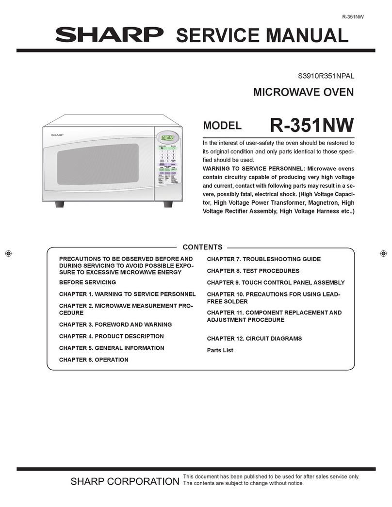
Sharp R-9360 User manual

R-9360
SHARP SERVICE MANUAL
S0506R9360J//
MICROWAVE OVEN
MODEL R-9360
In the interests of user-safety the set should be restored to its original
condition and only parts identical to those specified be used.
TABLE OF CONTENTS
Page
FOREWORD .................................................................................................................................................. 1
CAUTION, MICROWAVE RADIATION .............................................................................................................. 1
THUMB INDEX ............................................................................................................................................... 1
PRODUCT DESCRIPTION ................................................................................................................................ 2
OPERATING INSTRUCTIONS .......................................................................................................................... 3
OPERATION ................................................................................................................................................ 1 1
SERVICING ................................................................................................................................................. 16
TOUCH CONTROL PANEL ASSEMBLY ........................................................................................................... 23
COMPONENT REPLACEMENT AND ADJUSTMENT PROCEDURES ..................................................................... 38
MICROWAVE MEASUREMENT ...................................................................................................................... 45
SCHEMA-TIC DIAGRAM ................................................................................................................................ 46
PICTORIAL DIAGRAM .................................................................................................................................. 47
CONTROL PANEL CIRCUIT ........................................................................................................................... 49
PRINTED WIRING BOARD ............................................................................................................................. 51
PACKING AND ACCESSORIES ...................................................................................................................... 52
PARTS LIST ................................................................................................................................................ 53
SHARP CORPORATION


R-9360
SERVICE MANUAL
SHARP
R-9360
FOREWORD
PRODUCT DESCRIPTION
.‘:b&P
2
\\W>&,‘la
This Manual has been prepared to provide Sharp Service
Personnel with complete Operation and Service Information
for the Sharp Microwave Oven, R-9360.
It is recommended that service personnel carefully study the
entire text of this Manual so they will be qualified to render
satisfactory customer service.
CAUTION
ll_l----- ” <
I
1%;
-c,z OPERATING
,I INSTRUCTIONS
^
OPERATION
^“ran
MICROWAVE RADIATION
Personnel should not be exposed to the microwave energy
which may radiate from the magnetron or other microwave
generating devices if it is improperly used or connected.
All input and output microwave connections, waveguides,
flanges, and gaskets must be secured.
Never operate the device without a microwave energy ab-
sorbing load attached.
Never look into an open waveguide or antenna while the
device is energized.
SHARP CORPORATION
OSAKA, JAPAN
b
.i COMPONENT REPLACEMENT
$’ AND ADJUSTMENT PROCEDURE
I-, t
I
MICROWAVE MEASUREMENT
-I-‘;:PARTS LIST

R-9360
PRODUCT DESCRIPTION
EXPLANATION OF MICROWAVE COOKING
The Sharp Counter Top Microwave Oven uses microwave ener- Materials with a high moisture content, like most foods, will
gy to produce heat in the food to be cooked. Unlike conven- absorb microwave energy. As the microwave energy at a fre-
tional ovens microwave energy will cook foods without quency of 2450 Megahertz enters the food, the molecules align
applying external heat. themselves with the energy. Because the microwave are
changing polarity every half cycle, the food molecules are
Microwaves, which are short electromagnetic waves of RF (ra-
dio frequency) energy, pas5. .-;rrough materials such as glass,
paper, china and most plastics. Materials such as metal and
aluminum foil tend to reflect microwaves and may be used only
as recommended in the cooking instructions.
changing direction every half cycle or oscillating back and forth
4,900,000,000 times per second. This high speed oscillation
causes friction between the molecules, thereby converting the
microwave energy to heat.
SPECIFICATIONS
ITEMS DESCRIPTIONS
Power requirements 240V .
50Hz
Single phase, 3 wire earthed
Power consumption
Microwave output power
Case dimensions
Width
Height
Depth
Cooking cavity dimensions
Width
Height
Depth
Turntable diameter
Control complement
1.4kW
700W (2 litre water load)
622mm
382mm
476mm
406mm
248mm
422mm
395mm
Clock (l:OO- 12:59)
Minute Timer (O- 99 minutes 99 seconds)
Variable Cooking Mode Selector
Repetition Rate:
HIGH .........................Full power throughout the cooking time
MED HIGH .................24 sec. ON, 8 sec. OFF, approx. 70% of full power
MED ..........................18 sec. -CN, 14 sec. OFF, approx. 50% of full power
MED LOW
DEFROST ...................12 sec. ON, 20 sec. OFF, approx. 30% of full power
LOW ..........................6 sec. ON, 26 sec. OFF, approx. 10% of full power
Auto Start Cooking
Instant Cooking
Compu. Defrost Cooking
Ueight Approx. 27kg
2
R-9360
OPERATING INSTRUCTIONS
COMPU ME0 LOW ME0 HIGH
OEFROST ITI /\,// /F-l /\/1 /v-l
Ir\l /,\I 121 //\I Ir\l-
COOK AUTO K9
il
Minced beef - 1 Whole chvzken - 3 -
S&i& - 2 Chicken pieces - 4
Roast bed -3 Porkchops -5
Roast pork -3 lambchops -5
Roast iamb -3
I I I I
11 I2 13-t
4 5 6
t I I I
INDICATORS
Indicator lights for variable cooking, compu
defrost, auto start, cook and kg.
LIGHTED DIGITAL DISPLAY
Shows readout of cooking time, compu
defrost operation or time of day.
COMPU DEFROST PADS
Touch to select compu defrost setting.
COMPU DEFROST CHART
Foods cooked with compu defrost settings.
NUMBERING PADS
Touch to enter cooking times, clock time
or weights of food.
PROGRAM SELECTOR PADS
Touch to set clock, auto start or timer.
VARIABLE COOKING CONTROL PADS
Touch to select power setting.
If not touched, HIGH is automatically selected.
STOP PAD
I
Touch to stop operation of oven during cooking.
CLEAR PAD
Touch to erase during programming.
~sT?~~h~~tart oven.
INSTANT COOK PAD
Touch to cook for 1 minute at HIGH or increase
1 minute at variable cooking during cooking.
OPEN DOOR
i-
3

R-9360
CLOCK SETTING
Your oven functions as a clock to keep the time of day. To set the clock, follow this procedure.
When the oven is plugged in, the display will show [m,$?fl and variable cooking indicators flashing
each second. Touch the CLEAR pad; [::l;‘:_;‘] will appear. After one minute the display will show
r-1 *
* Suppose you want to enter the correct time of day 1230 (A.M. or P.M.)
,,.,.,.,,,,:,;,:,,
2. Enter the correct time of day
by touching the numbers in
sequence.
3. Touch the AUTO START/CLOCK
pad again.
Pad Order I Display
Au-r0 SW
CLOCK
I ,i 1 I7
1L -1 LI
I 1 l ,7 I7
II- l -//-I
The clock is now set and will keep the time of day. If power to the unit is interrupted, all in-
dicators will light and -1 and variable cooking indicators will flash on and off every second,
after the power is reinstated. To reset the clock, touch the CLEAR pad and then repeat the steps
above.
NOTE: * This is a 12-hour clock. ]E/~/%~j will appear in the readout if you attempt to enter in-
correct clock time. For example, if you attempt to enter 8:61 or 13:00, [m]and
incorrect clock time will appear repeatedly. To erase [E,c,c3lcj touch the CLEAR pad.
If you accidentaly touch more than 4 number pads, the last 4 numbers you have
touched will appear on the display.
MINUTE TIMER SETTING
This oven can be used as a timer for timing up to 99 minutes, 99 seconds. There is no cooking
involved.
* Suppose you want to time a 3 minute long distance phone call.
Procedure Pad Order Display
1. Enter desired time.
2. Touch the TIMER pad.
The timer will begin counting down to zero. When the timer reaches zero, the signal will sound.
The time of day will reappear on the display. To cancel the minute timer during operation, simply
touch the CLEAR pad and the time of day will reappear.

R-9360
MICROWAVE COOKING
Multiple Sequence Cooking
Your oven can be programmed for up to 3 automatic cooking sequences, switching from one
variable power setting to another automatically.
Check the microwave recipe section of your Sharp Carousel Microwave Cookbook for ideas on
when to use multiple sequence cooking.
* Suppose you want to roast beef for 5 minutes at HIGH, and continue to cook for 30 minutes at
MED HIGH. -
Procedure Pad Order Display
1. Enter desired time for first cooking
sequence. -_ p--l/1ipJ 71
2. Select first variable cooking control
setting.
--
3. Enter desired time for second
cooking sequence. ~p-lp-p-j - 3E-q
4. Select second variable cooking
control setting.
5. Touch the START pad. pi&T-j
VI
The timer will count down
the first sequence and when
it reaches zero, the second
sequence will appear on
display and begin a count
down.
WI
When the timer reaches zero, all indicators will go out and an audible signalwill sound. The time of
day will reappear on the display.
NOTE: If HIGH is selected as the final sequence, it is not necessary to touch the HIGH pad.
If HIGH is programmed as the first or second sequence, the HIGH pad must be touched.
If you accidentally touch the wrong variable cooking control pad, immediately touch the
correct pad. The last pad touched will be the setting the oven accepts. For example, if
you touch the MED HIGH pad and then immediately touch the MED pad, the oven will
cook at MED.
OF’ERATION FOR INSTANT COOK’”
The “Instant Cook” system allows you to cook for an extra minute at HIGH by simply touching
the “INSTANT COOK” pad. You can also extend cooking time in multiples of 1 minute by
repeatedly touching the “INSTANT COOK” pad during a cooking program.
5

R-9360
* Suppose you want to cook 1 minute at HIGH easily.
Procedure Pad Order
,
Display
Touch the INSTANT COOK pad. JINSII\NT] /i:ylK :.,y/!q
The timer begins to count
down.
When the timer reaches zero, all indicators will go out and an audible signal will sound. The time of
day will reappear on the display.
NOTE: The Instant Cook system can be only inputted within 1 minute after cooking or closing the
door. The Instant Cook can’t be used to start the oven if any program is on display.
+ Suppose you want to increase 1 minute cooking time during 5 minutes at MED HIGH cooking.
I Procedure
r
1. Enter desired cooking time.
2. Select desired variable cooking control
setting.
3. Touch the START pad.
4. Touch the INSTANT COOK pad.
Pad Order
P--lmm
M.HIGH
Display
r-- i-ii-l
-I i-1i-1
MED HIGH
c r-i I7
-I l i-i i-i
I MED HIGH
1 COOK 1
The timer begins to count
down.
MED HIGH I
I 2 I7
I l -I i-i
COOK
The cooking time is increas-
ed 1 minute and continues
to count down.
When the timer reaches zero, all indicators will go out and an audible signal will sound. The time of
day will reappear on the display.
NOTE: The cooking time can be increased in multiples of 1minute by repeatedly touchingthe
“INSTANT COOK” pad during the cooking program.
OPERATIONFORCOMPU DEFROST‘"COOKING
Your Sharp Microwave Oven has special function keys to defrost meats faster and better.
Compu Defrost 1 - 5 automatically defrosts minced beef, steak, whole chicken, chicken pieces and
chops. Each key has 3 cooking stages. Select the desired Compu Defrost number and input the
food weight by using the number pads.
6

* Suppose you want to defrost 1.36 kg steak by Compu Defrost.
Procedure Pad Order
1. Select food category for
Compu Defrost. l--i 2
Display
COMPU i- i-1 \ I i- i-i
DEFFoSTI- i-i 1,I, i-i
-1
COVER and EDGE WIII be
displayed repeatedly and
COMPU DEFROST ap-
pears, the kg symbol WIII
continue to flash calling
for you to enter the weight
Into the oven.
2. Touch number pads to enter weight.
(Ex: 1.36 kg should be 1.4 kg)
Flashing of kg stops and
kg goes on.
3. Touch the START pad.
1.4 and kg will go off
and 13.27 will appear.
VI
The timer begins to count down. When the 1st stage finishes, an
audible signal will sound and oven is stopped.
pii5~,i~~,i\~ 1
p----fq
-1
-1
TURN, OVER and COVER,
EDGE will be displayed
repeatedly.
4. Open the door. Turn over and shield
the hot portions.
R-9360
7

R-9360
Procedure
5. Please place food in the oven.
Close the door.
Pad Order Display .
Touch the START pad.
I J
START will be displayed.
i MED
The timer begins to count down. When the 2nd stage finishes, an
audible signal will sound.
The 3rd stage continues after the 2nd stage without stopping.
The cooking time will count down to zero. When the timer reaches
zero, an audible signal will sound.
L /
STAND will be displayed
continuously.
When door is opened or the CLEAR pad is touched, STAND will go out and the time of day will
appear on the display.
NOTE:
1. To enter 1 kg into the oven it is necessary to press key pad 1 then 0. Kilograms should be rounded
off to the nearest 0.1 kg.
(Example: 1.75 kg should be rounded off to 1.8 kg)
2. Foods weighing more or less than the quantity listed in the chart should be defrosted following
guidelines in the cookbook. If the incorrect weight is entered and the START pad is touched,
-1 and incorrect weight will be displayed repeatedly. The CLEAR pad has to be touched
to reprogram the oven.

R-9360
Compu-Defrost’“Chart
L.- --.-
Compu Defrost
Setting Food
Minced
beef
Amount
0.5
215 kg
Display Procedure Comment
I
4
l----l
5
Steak 0.2
I
2.0 kg
l Before defrosting . . .
Shield the edge and
the thin portions.
l After the 1st stage . . .
Turn over and shield
the’warm portions.
l After the 2nd stage
. . . If there are warm
portions, shield them.
Stand,
10-15 covered ‘2
minutes.,
Whole
chicken
Roast beef
1.0
I
[‘I -1 l Before defrosting . . .
Shield the thin por-
3.0 kg tions, wing tips and
pork
lamb legs.
I- im l Afterthe1St stage
J=8:‘ERlm . . . Turn over and
shield the warm
portions.
Stand, covered .
IO-15 minutes. :
]C,“:IEm -1 l After the 2nd stage
. . . If there are warm
portions, shield them.
___ --- .- __----.-
Chicken
pieces 0.2
I
1.5 kg
[TI::7::lm] l After the 1st stage 3
r
,r
I- -1 . . . Turn over and . -2
1
rearrange. “k:
r
[,cE- -1 l After the 2nd stage i
. . . If there are warm Stand, covered i
or thawed portions, 1O-l 5 minutes.
rearrange or remove. L~
Pork chops 0.5
I pm-j-]
Lamb chops 3.0 kg j-TF---ypFKj
JKE--I8RRNC1
___--
l After the 1st stage
. * . Turn over and
rearrange.
l After the 2nd stage
. . . If there are warm
or thawed portions,
rearrange or remove.
/
7
------I
Stand, covered
lo-15 minutes.
NOTE: On No. 2 and 5 key, remove any thawed steaks and chops only after the second stage, if
necessary.
9

R-9360
AUTO START SETTING
If you wish to program your oven to begin cooking automatically at a designated time of day,
follow this procedure:
* Suppose you want to start cooking a stew for 50 minutes on MED at 4:30 this afternoon.
Before setting, check to make sure the clock is showing the correct time of day.
Procedure
1. Enter the desired start time.
2. Touch the AUTO START/CLOCK
pad.
3. Enter the desired cooking time.
4. Select desired ME D setting.
5. Touch the START pad.
Pad Order
/%FJ
I
MED
Display
The colon (:) will flash on
and off. I
Suppose you are setting at
1:OO p.m.
I I
--
I : :ly:
AUTO
The oven will commence to
cook at 4:30 P.M.
/I
The cooking time will count down to zero. When the timer reaches zero, all indicators will go out
and an audible signal will sound. The time of day will reappear on the display.
NOTE: The Auto Start feature can be used for any of the programs described on the previous
pages except Compu Defrost settings.
Once you have correctly programmed the oven for Auto Start, the correct time of day
(not the Auto Start time) will appear on the display. To check the programmed Auto
Start time, touch the AUTO START/CLOCK pad. The programmed Auto Start time will
appear on display as long as your finger is touching the pad.
To cancel Auto Start, simply touch the STOP pad and then the CLEAR pad.
TO CANCEL A PROGRAM DURING COOKING
If you are in the process of cooking and wish to stop the oven and cancel the entire cooking
program, follow either of the steps below:
1. Open the oven door. 2. Close the door. 3. Touch the CLEAR pad.
or
1. Touch the STOP pad. 2. Touch the CLEAR pad.
WHEN ELECTRICAL POWER IS INTERRUPTED
If the electrical power supply to your microwave oven should be interrupted, all digital display and
indicator lights will appear after the power is reinstated.
ing program and the time of day will be erased. If this occurs during cooking, your cook-
Simply reset the clock for the correct time of day.
10

R-9360
OPERATION
DESCRIPTION OF OPERATING SEQUENCE
The following is a complete description of component func-
tions during oven operation.
OFF CONDITION
Closing the door activates both door interlock switches; low-
er latch switch and upper latch switch.
(In this condition, the monitor switch contacts are opened)
The stop switch is activated (contacis closed) by the lower
latch head, when the door is closed.
When oven is plugged in, the power supply voltage is added
to the control unit. But no components in the oven will oper-
ate, (Figure O-l) -.
Note: When the door is opened by pushing the door open but-
ton, the oven lamp comes on.
1. The display will show flashing “88:88”.
To set any program or set the clock, you must first touch
the STOP/CLEAR pad. The display will clear, and 1:OO will
appear and count up every minute.
COOKING CONDITION
1. HIGH COOKING
Program desired cooking time and Variable Cooking Con-
trol by touching the NUMBER pads and the HIGH pad of the
Variable Cooking Control.
When the COOK (or START) pad is touched, the following
operations occur:
l-l.
1-2.
l-3.
1-4.
1-5.
1-6.
1-7.
1-8.
The power transformer, oven lamp, etc. are turned on.
(For details, refer to Figure O-2.)
The power supply voltage is added to the primary
winding of the power transformer and is converted
to about 3 volts A.C. output on the filament winding,
and approximately 2300 volts A.C on the high vol-
tage winding.
About 3 volts A.C. output from the filament winding
heats the megnetron filament.
The 2300 volts A.C. is converted to approximately
4000 negative D.C. volts by the voltage doubler cir-
cuit consisting of a H.V. capacitor and rectifier and
sent to the magnetron cathode.
This causes the magnetron to oscillate and produce
the 2450 MHz cooking frequency.
This RF energy is channeled through the waveguide
into the cavity feed-box, and then into the cavity
where the food is placed to be cooked.
Upon completion of the cooking time, the power trans-
former, oven lamp, etc. are turned off, and the gener-
ation of microwave energy is stopped. The oven will
revert to the OFF condition.
When the door is opened during a cook cycle, the latch
switches, stop switch and monitor switch are activat-
ed with the following results. The circuits to the turnt-
able motor, the cooling fan motor, and the high voltage
components are deenergized, the oven lamp remains
on, and the digital readout displays the time still re-
maining in the cook cycle when the door was opened.
l-9. The monitor switch is electrically monitoring the oper-
ation of the upper latch switch and is mechanically
associated with the door so that it will function in the
following sequence.
(1) When the door opens from a closed position, the
upper latch switch opens their contacts, and then
the monitor switch contacts close.
(2) When the door is closed from the open position,
the monitor switch contacts first open, and then
the contacts of the upper latch switch closes.
If the upper latch switch fails with its contacts closed when
the door is opened, the closing of the monitor switch contacts
will form a short circuit through the fuse, temp. fuse, upper
latch switch, causing the monitor fuse to blow.
2. MED HIGH, MED, MED LOW or LOW COOKING.
When the Variable Cooking is programed, power supply vol-
tage is supplied to the power transformer intermittently
through the contacts of the cook relay which is operated
by the control unit within a 32 second time base.
The microwave power operation is as follows:
HIGH
ME0
HIGH
ME0
ME0
LOW
LOW
t-
ON 32 sec.
-8 sec.
m 24 sec. OFF
ON - 14 sec.
OFF I
ON 20 sec.
12 sec. OFF I
6 sec.
MICROWAVE POWER
= 100%
MICROWAVE POWER
= Approx. 70%
MICROWAVE POWER
= Approx. 50%
MICROWAVE POWER
= Approx. 30%
MICROWAVE POWER
= Approx 10%
Note: The ON/OFF time ratio does not correspond with the per-
centage of microwave power, because approx. 2 se-
conds are needed for heating of the magnetron filament.
11

3. COMPU DEFROST COOKING
The COMPU DEFROST key is a special function key to
defrost meats and poultry faster and better.
COMPU DEFROST 1 to 5 automatically defrosts minced
beef, steak, whole chicken, chicken pieces and chops.
Each key has 3 defrost stages.
When the desired COMPU DEFROST number is selected and
the food weight is entered by using the number pad’s, the
oven will cook according to the special cooking sequence,
refer to page 9.
12

R-9360 -
240V 50Hz
SCHEMETIC
NOTE: CONDITION
OF OVEN
1. DOOR CLOSED
2. CLOCK APPEARS
ON DISPLAY
MONITOR SWITCH
CONTROL ’
UNIT I
iTOP
iWITCH
I--------- J
FAN MOTOR
TURNTABLE MOTOR
POWER TRANSFORMER
I -----
sHqg?y~~
PROTECTOR ’
1
FUSE
MlOA
I
I TEMP
FUSE
1
J LOWER
LATCH
SWITCH
Figure O-l. Oven Schematic-Off Condition
13

R-9360
240V 50Hz
SCHEMATIC
NOTE: CONDITION
OF OVEN
1. DOOR CLOSED
2. COOKING TIME
PROGRAMMED
3. VARIABLE
COOKING
CONTROL
HIGH
4. “START” PAD
TOUCHED
I O/O
MONITOR SWITCH t
UPPER
LATCH
SWITCH
7 1
OVEN LAMP .
I A2
STOP
SWITCH
IA6
FAN MOTOR
SHORT
PROTECTOR
MAGNETRON
1
1FUSE
MlOA
1
1
1TEMP
FUSE
1
b LOWER
LATCH
) SWITCH
---TURNTABLE MOTOR
POWER TRANSFORMER
Figure O-2. Oven Schematic-Cooking Condition
14

R-9360
DESCRIPTION AND FUNCTION OF COMPONENTS
DOOR OPEN MECHANISM
The door can be opened by pushing the open button on the
control panel, refer to Figure D-l. When the open button is
pushed, the open plate on the open device pushes in the door
lever on the door, operating the latch head linkage. The lower
and upper latch heads are moved upward, and released from
the lower and upper latch hooks. Now, the door can be opened.
DOOR
\ / ASSEMBLY
OPkN
BUTTON
Figure D-1. Door Open Mechanism
LOWER AND UPPER LATCH SWITCHES
The lower latch switch is mounted in the lower latch hook and
the upper latch switch is mounted in the upper latch hook. They
are activated by the latch heads on the door. When the door
is opened, the switches interrupt the circuit to all components
except the oven lamps.
A cook cycle cannot take place until the door is firmly closed
thereby activating both interlock switches.
MONITOR SWITCH
The monitor switch, mounted on the upper latch hook, is acti-
vated (the contacts opened) by the upper latch head on the
door while the door is closed. This switch is intended to render
the oven inoperative by means of blowing the fuse when the
contacts of the upper latch switch failes to open when the door
is opened.
Functions:
1. When the door is opened, the monitor switch contacts close
(to ON condition) due to their being normally closed. At this
time the upper latch switch is in the OFF condition (con-
tacts open) due to their being normally open contact
switches.
2. As the door goes to a closed position, the monitor switch
contacts are first opened and then the upper latch switch
contacts close. (On opening the door, each of these
switches operate inversely.)
3. If the door is opened and the upper latch switch contacts
fail to open, the fuse blows simultaneously with the clos-
ing of the monitor switch contacts.
CAUTION: BEFORE REPLACING A BLOWN FUSE, TEST
THE UPPER LATCH SWITCH SWITCH AND
MONITOR SWITCH FOR PROPER OPERATION.
(REFER TO CHAPTER “TEST PROCEDURE”)
I
IT0
CH
LATCH
SWITCH
LOWER
LATCH
I
STOP
SWITCH
STOP
SWITCH
LEVER
t’ LOWER
LATCH
SWITCH
Figure D-2. Latch Switches and Monitor Switch
15

R-9360
SERVICING
TROUBLESHOOTING GUIDE
When troubleshooting the microwave oven, it is helpful to fol-
low the Sequence of Operation in performing the checks. Many
of the possible causes of trouble will require that a specific test
be performed. These tests are given a procedure letter which
will be found in the “Test Procedures” section.
IMPORTANT: If the oven becomes inoperative because of a
blown monitor fuse in the upper latch switch-
monitor-switch circuit, check the upper latch
switch and monitor switch before replacing the
monitor fuse.
PROBLEM POSSIBLE CAUSE TEST PROCEDURE OR
CORRECTION
OFF CONDITION
Home fuse blows when power cord Shorted wire in power cord or wire harness. Replace cord or check wiring.
is plugged into wall receptacle.
Monitor fuse blows when power Shorted wire in power cord or wire harness. Replace power cord or check and
cord is plugged into wall receptacle. repair wire harness.
Defective monitor switch. Procedure F.
88:88 do not appear in display No power at outlet. Check home fuse.
when power cord is first plugged
into wail outlet. Blown monitor fuse. Procedure G.
Blown magnetron temp. fuse. Procedure H.
Open wire in power cord, wiring harness, Replace or repair wiring.
or wiring between control panel assembly
units.
Display does not operate properly
when STOP/CLEAR key is touched.
(Buzzer should sound and time of
day should appear in display.)
&en lamps do not light with
door opened.
Defective control unit. Procedure I.
Defective key unit. Procedure J.
Defective control unit. Procedure I.
Defective stop switch. Procedure E.
No power in home. Check wall outlet.
Open wire in power cord or wire harness.
Defective oven lamp.
Defective lower latch switch.
Open or loose wire connection to the
above components.
Replace same or repair wiring.
Replace.
Procedure E.
Check wiring.
Blown monitor fuse or magnetron temp.
fuse.
Procedure G or H.
16

R-9360
TROUBLESHOOTING GUIDE (CONT’D)
PROBLEM POSSIBLE CAUSE TEST PROCEDURE OR
CORRECTION
COOKING CONDITION
Oven lamps do not light in cook Defective control relay (RY-1) of control unit. Procedure I.
cycle.
(Does light when door is opened) Defective control unit. Procedure I.
Oven lamps do not light at all. Burned out bulb. Replace.
Open wiring to oven lamp. Check and repair wiring.
Oven lamps light, but turntable Defective control relay (RY-1) of.control unit. Procedure I.
motor does not operate. Defective turntable motor. Replace.
Turntable motor operates. Defective cooling fan motor. Replace.
normally but fan motor does not
operate. Open or loose wiring to the fan motor. Check and repair wiring.
Oven does not go into a cook Interlock switches defective or out of Procedures E.
cycle when START key is touched. adjustment.
Defective cook relay (RY-2) of control unit. Procedure I.
Defective control unit. Procedure I.
Defective key unit. Procedure J.
Open or loose wiring to above components. Check and repair wiring.
Oven seems to be operating but lit- Defective magnetron. Procedure A.
tle or no heat is produced in oven
load. (Food incompletely cooked or Defective cook relay (RY-2) of control unit. Procedure I.
not cooked at all at end of cook
cycle) Defective power transformer. Procedure B.
Defective rectifier. Procedure C.
Defective high voltage capacitor. Procedure D.
Defective control unit. Procedure I.
Open or loose wiring to above components. Check and repair wiring.
Oven goes into a cook cycle but Turntable motor does not operate. Refer to preceding turntable
extremely uneven heating is motor problem.
produced in oven load (food).
Oven does not cook properly when
programmed for variable cooking
mode.
(Operates properly on HIGH)
Defective control unit.
Defective key unit.
Open or loose wiring between above
components.
Procedure I.
Procedure J.
Check and repair wiring.
17

R-9360
TEST PROCEDURES
PROCEDURE COMPONENT TEST
LETTER
A MAGNETRON ASSEMBLY TEST
DISCHARGE THE HIGH VOLTAGE CAPACITOR BEFORE TOUCHING ANY OVEN
COMPONENTS OR WIRING.
To test for an open filament, isolate the magnetron from the high voltage circuit. A continuity check across
the magnetron filament leads should indicate less than 1 ohm.
To test for a shorted magnetron, connect the ohmmeter leads between the magnetron filament leads and
chassis ground. This test should indicate an infinite resistance. If there is little or no resistance, the magne-
tron is grounded and must be replaced.
Power output of the magnetron can be measured by performing a water temperature rise test. This test
should only be used if above tests do not indicate a faulty magnetron and there is no defect in the following
components or wiring: rectifier, high voltage capacitor, heater transformer and power transformer.
MICROWAVE OUTPUT POWER
Microwave output power from the magnetron can be measured by way of substitution, i.e. it can be meas-
ured by using water load how much it can be absorbed by the water load. To measure the microwave output
power in the microwave oven, the relation of calorie and watt is used.
When P (W) heating works for t (second), approximately P.t/4.2 calorie is generated. On the other hand,
if the temperature of the water with V (ml) rises AT (“C) during this microwave heating period, the calorie
of the water is V.AT.
The formular is as follows;
Pet
- =VaAT
4.2
P= 4.2 . : . AT (w) .
Our condition for the water load is as follows;
Water load .. ... 2000 ml
Heating time .... 120 seconds (2 minutes)
/I
Measuring method;
1. Put the water load of two (2) litres on the center of the oven shelf.
The water load should be arranged in two (2) Pyrex beakers, the size of which is one (1) litre, and be
placed at right and left, side by side, on the oven shelf.
2. Measure the temperature of water before heating and also after heating during two minutes by micro-
wave, and calculate the temperature rise.
The temperature rise should be the average of temperature differences measured in each beaker.
3. The output power should be calculated as follows.
In case the measuring result is not satisfactory, execute the measurement several times and judge the
result from the synthetic point of view.
Microwave output power should be within f 15% of the nominal one.
18
Table of contents
Other Sharp Microwave Oven manuals

Sharp
Sharp R-200 User manual

Sharp
Sharp R642WW User manual

Sharp
Sharp R-200 User manual

Sharp
Sharp R-290H User manual

Sharp
Sharp R-370EK User manual

Sharp
Sharp Carousel R1514TY Use and care manual

Sharp
Sharp R260 User manual

Sharp
Sharp R-299T(S) Technical specifications

Sharp
Sharp R-678P User manual

Sharp
Sharp Carousel R-1214 Specification sheet

Sharp
Sharp R-402FW User manual

Sharp
Sharp R-343WM User manual

Sharp
Sharp R-380D User manual

Sharp
Sharp KB6002LS - 1.0 cu. Ft. Microwave Drawer Assembly instructions

Sharp
Sharp R-222STWE User manual

Sharp
Sharp R-204EWA User manual

Sharp
Sharp R-8000E User manual

Sharp
Sharp YC-MS01E-S User manual

Sharp
Sharp R-8000G User manual

Sharp
Sharp R-370E User manual