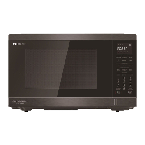
Sharp R-939(BK) User manual

CHAPTER 1. BEFORE SERVICING
CHAPTER 2. WARNING TO SERVICE PERSONNEL
CHAPTER 3. PRODUCT SPECIFICATIONS
CHAPTER 4. APPEARANCE VIEW
CHAPTER 5. OPERATION SEQUENCE
CHAPTER 6. FUNCTION OF IMPORTANT COMPO-
NENTS
CHAPTER 7. TROUBLESHOOTING GUIDE
CHAPTER 8. TEST PROCEDURES
CHAPTER 9. TOUCH CONTROL PANEL ASSEMBLY
CHAPTER 10. PRECAUTIONS FOR USING LEAD-
FREE SOLDER
CHAPTER 11. COMPONENT REPLACEMENT AND
ADJUSTMENT PROCEDURE
CHAPTER 12. MICROWAVE MEASUREMENT
CHAPTER 13. TEST DATA AT A GLANCE
CHAPTER 14. CIRCUIT DIAGRAMS
Parts List
S9614R939PHW/
SERVICE MANUAL
R939(W)
CONTENTS
This document has been published to be used for
after sales service only.
The contents are subject to change without notice.
TopPage
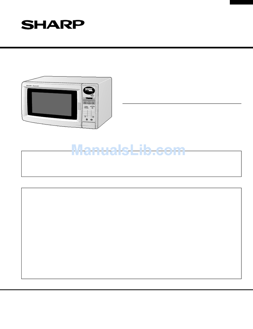
MICROWAVE OVEN WITH
GRILL AND CONVECTION
R-939(BK)
R-939(IN)
R-939(W)
MODELS
In interests of user-safety the oven should be restored to its
original condition and only parts identical to those specified
should be used.

CONTENTS
CHAPTER 1. BEFORE SERVICING
[1] GENERAL IMPORTANT INFORMA-
TION ........................................................... 1-1
[2] WARNING................................................... 1-1
[3] CAUTION MICROWAVE RADIATION ........ 1-2
CHAPTER 2. WARNING TO SERVICE PERSON-
NEL
CHAPTER 3. PRODUCT SPECIFICATIONS
CHAPTER 4. APPEARANCE VIEW
[1] OVEN.......................................................... 4-1
[2] TOUCH CONTROL PANEL ........................ 4-1
CHAPTER 5. OPERATION SEQUENCE
[1] OFF CONDITION........................................ 5-1
[2] MICROWAVE COOKING CONDITION....... 5-1
[3] GRILL COOKING CONDITION .................. 5-2
[4] CONVECTION COOKING CONDITION..... 5-2
[5] DUAL COOKING CONDITION ................... 5-2
[6] ON/OFF TIME RATIO ................................. 5-3
[7] AUTOMATIC COOKING ............................. 5-3
[8] POWER OUTPUT REDUCTION ................ 5-3
[9] FAN MOTOR OPERATION......................... 5-3
[10] CONVECTION MOTOR OPERATION........ 5-3
CHAPTER 6. FUNCTION OF IMPORTANT COM-
PONENTS
[1] DOOR OPEN MECHANISM ....................... 6-1
[2] MONITORED LATCH SWITCH (SW1) ....... 6-1
[3] STOP SWITCH (SW2)................................ 6-1
[4] MONITOR SWITCH (SW3)......................... 6-1
[5] FUSE (F1) 20A 250V .................................. 6-1
[6] FUSE (F2) F8A 250V (NOISE FILTER) ...... 6-1
[7] TC TRANSFORMER .................................. 6-1
[8] THERMAL CUT-OUT (TC1) 125C (MG)..... 6-1
[9] THERMAL CUT-OUT (TC2) 170C
(GRILL) ....................................................... 6-1
[10] THERMAL CUT-OUT (TC3) 170C
(CONV.)....................................................... 6-1
[11] ASYMMETRIC RECTIFIER ........................ 6-1
[12] NOISE FILTER............................................ 6-2
[13] TURNTABLE MOTOR (TTM)...................... 6-2
[14] FAN MOTOR (FM) ...................................... 6-2
[15] CONVECTION MOTOR (CM)..................... 6-2
[16] GRILL HEATING ELEMENT (GH) .............. 6-2
[17] CONVECTION HEATING ELEMENT
(CH) ............................................................ 6-2
[18] CONVECTION COOKING SYSTEM .......... 6-2
[19] FIRE SENSING FEATURE ......................... 6-2
[20] OPEN JUDGE BY THERMISTOR .............. 6-2
[21] DAMPER OPEN-CLOSE MECHANISM..... 6-2
CHAPTER 7. TROUBLESHOOTING GUIDE
[1] FOREWORD............................................... 7-1
[2] CHART........................................................ 7-2
CHAPTER 8. TEST PROCEDURES
[1] Procedure A: MAGNETRON TEST ............ 8-1
[2] Procedure B: HIGH VOLTAGE TRANS-
FORMER TEST .......................................... 8-2
[3] Procedure C: HIGH VOLTAGE RECTIFI-
ER TEST..................................................... 8-2
[4] Procedure D: HIGH VOLTAGE CAPACI-
TOR TEST .................................................. 8-2
[5] Procedure E: SWITCH TEST...................... 8-3
[6] Procedure F: THERMISTOR TEST ............ 8-3
[7] Procedure G: THERMAL CUT-OUT
TEST........................................................... 8-3
[8] Procedure H: MOTOR WINDING TEST..... 8-3
[9] Procedure I: NOISE FILTER TEST............. 8-4
[10] Procedure J: BLOWN FUSE (F1) 20A........ 8-4
[11] Procedure K: BLOWN FUSE (F2) 8A
(NOISE FILTER) ......................................... 8-4
[12] Procedure L: GRILL HEATING ELE-
MENTS (TOP) AND CONVECTION
HEATING ELEMENT TEST ........................ 8-4
[13] Procedure M: CONTROL PANEL AS-
SEMBLY TEST ........................................... 8-4
[14] Procedure N: JOG AND SWITCH UNIT
TEST........................................................... 8-5
[15] Procedure O: RELAY TEST ........................ 8-6
[16] Procedure P: PROCEDURES TO BE
TAKEN WHEN THE FOIL PATTERN ON
THE PRINTED WIRING BOARD (PWB)
IS OPEN ..................................................... 8-6
CHAPTER 9. TOUCH CONTROL PANEL ASSEM-
BLY
[1] OUTLINE OF TOUCH CONTROL PAN-
EL ............................................................... 9-1
[2] SERVICING FOR TOUCH CONTROL
PANEL ........................................................ 9-1
CHAPTER 10. PRECAUTIONS FOR USING LEAD-
FREE SOLDER
CHAPTER 11. COMPONENT REPLACEMENT
AND ADJUSTMENT PROCEDURE
[1] BEFORE OPERATING ..............................11-1
[2] OUTER CASE REMOVAL .........................11-1
[3] HIGH VOLTAGE COMPONENTS RE-
MOVAL.......................................................11-1
[4] HIGH VOLTAGE TRANSFORMER RE-
MOVAL.......................................................11-2
[5] MAGNETRON REMOVAL .........................11-2
[6] CONTROL PANEL ASSEMBLY RE-
MOVAL.......................................................11-2
[7] FAN MOTOR REREPLACEMENT.............11-2
[8] TURNTABLE MOTOR REPLACEMENT....11-3
[9] CONVECTION MOTOR AND CONVEC-
TION HEATING ELEMENT REMOVAL .....11-3
[10] POSITIVE LOCK........................................11-4
[11] OVEN LAMP SOCKET REMOVAL............11-4
R939(W)
1 – 1
R939(W) Service Manual
CHAPTER 1. BEFORE SERVICING
[1] GENERAL IMPORTANT INFORMATION
This Manual has been prepared to provide Sharp Corp. Service engineers with Operation and Service Information.
It is recommended that service engineers carefully study the entire text of this manual, so they will be qualified to render satisfactory customer ser-
vice.
[2] WARNING
Never operate the oven until the following points are ensured.
(A) The door is tightly closed.
(B) The door brackets and hinges are not defective.
(C) The door packing is not damaged.
(D) The door is not deformed or warped.
(E) There is not any other visible damage with the oven.
Servicing and repair work must be carried out only by trained service engineers.
Removal of the outer wrap gives access to potentials above 250V.
All the parts marked “*” on parts list may cause undue microwave exposure, by themselves, or when they are damaged,
loosened or removed.
WARNING: THIS APPLIANCE MUST BE EARTHED
IMPORTANT
THE WIRES IN THIS MAINS LEAD ARE COLOURED IN ACCORDANCE WITH THE FOLLOWING CODE:
GREEN-AND-YELLOW --------------EARTH
BLUE -----------------------------------NEUTRAL
BROWN ---------------------------------------LIVE

R939(W)
1 – 2
[3] CAUTION MICROWAVE RADIATION
Personnel should not be exposed to the microwave energy which may radiate from the
magnetron or other microwave generating devices if it is improperly used or connected.
All input and output microwave connections, waveguides, flanges and gaskets must be
secured.
Never operate the device without a microwave energy absorbing load attached.
Never look into an open waveguide or antenna while the device is energized.

R939(W)
2 – 1
R939(W) Service Manual
CHAPTER 2. WARNING TO SERVICE PERSONNEL
REMEMBER TO CHECK 3D
1) Disconnect the supply.
2) Door opened, and wedged open.
3) Discharge high voltage capacitor.
WARNING: AGAINST THE CHARGE OF THE
HIGH-VOLTAGE CAPACITOR
GB Microwave ovens contain circuitry capable of producing very high voltage and current, contact with following
parts will result in electrocution.
High voltage capacitor, High voltage transformer, Magnetron, High voltage rectifier assembly, High voltage
harness.
REMEMBER TO CHECK 4R
1) Reconnect all leads removed from components dur-
ing testing.
2) Replace the outer case (cabinet).
3) Reconnect the supply.
4) Run the oven. Check all functions.
NL Magnetronovens bevatten circuits die een zeer hoge spanning en stroom kunnen voortbrengen. Contact met de
volgende onderdelen kan elektrocutie tot gevolg hebben.
Hoogspanningscondensator, hoogspanningstransformator, magnetron, hoogspanningsgelijkrichter, hoogspannings
kabelboom.
VERGEET DE VOLGENDE 3 STAPPEN NIET
1) Haal de stekker uit het stopcontact.
2) Open de deur en zorg ervoor dat hij niet dicht kan vallen.
3) Ontlaad de hoogspanningscondensator.
PAS OP VOOR DE ELECTRISCHE LADING VAN DE
HOOGSPANNINGSCONDENSATOR
VERGEET DE VOLGENDE 4 STAPPEN NIET
1) Sluit de draden weer aan diezijn losgehaald voor de test.
2) Plaats de buitenmantel weer om het toestel heen (kabinet).
3) Stop de stekker weer in het stopcontact.
4) Zet de oven aan. Controleer alle functies.
Wanneer alle reparaties zijn uitgevoerd en de oven weer in
elkaar is gezet, moet de het magnetronvermogen worden
gecontroleerd en moet worden gecontroleerd of er geen
microgolflekkage is.
The high-voltage capacitor remains charged about
60 econds after the oven has been switched off. Wait
for 60 seconds and then short-circuit the connection
ofthe high-voltage capacitor (that is, of the connectin-
glead of the high-voltage rectifier) against the chas-
siswith the use of an insulated screwdriver.
Sharp recommend that wherever possible fault-findingis
carried out with the supply disconnected. It may in,some
cases, be necessary to connect the supply after the out-
er case has been removed, in this event carry out 3D
checks and then disconnect the leads to the primary of
the high voltage transformer. Ensure that these leadsre-
main isolated from other components and the oven chas-
sis. (Use insulation tape if necessary.) When the testing
is completed carry out 3D checks and reconnectthe
leads to the primary of the high voltage transformer.
Microwave ovens should not be run empty. To test for
the presence of microwave energy within a cavity, place
a cup of cold water on the oven turntable, close the door
and set the power to HIGH and set the microwave timer
for two (2) minutes. When the two minutes has elapsed
(timer at zero) carefully check that the water is now hot.If
the water remains cold carry out 3D checks and re-
examine the connections to the component being tested.
When all service work is completed, and the oven is
fully assembled, the microwave power output should
be checked and a microwave leakage test should be
carriedout.
De hoogspanningscondensator blijft nog ongeveer 60
seconden lang opgeladen, nadat de oven is uitgeschakeld.
Wacht 60 seconden voordat u de verbinding van de
hoogspannings-condensator (m.a.w. de verbindingsdraad
van de hoogspanningsgelijkrichter) met een ge soleerde
schroevedraaier kortsluit tegen het chassis.
Sharp beveelt ten sterkste aan dat, voor zover mogelijk,
defecten worden opgespoord wanneer de stekker uit het
stopcontact is gehaald. Soms is het nodig om de stroomtoevoer
weer tot stand te brengen nadat de buitenmantel verwijderd is.
Herhaal dan de bovengenoemde 3 stappen en haal
deelectrische draden uit de primaire zijde van de
vermogenstransformator. Zorg ervoor dat deze draden
ge•soleerd blijven van andere elementen en van het chassis
van de oven. (Gebruik zo nodig isolatieband.) Wanneer de
test is uitgevoerd, herhaalt u de bovenstaande 3 stappen en
verbindt u de electrische draden weer aan de primaire zijde
van de vermogenstransformator.
Magnetronovens mogen niet leeg aangezet worden. Om te
controleren of er microgolf-energie binnen de oven wordt
geproduceerd, plaatst u een mok met koud water op de
draaitafel van de oven, sluit de deur, zet de oven op HIGH en
stelt de klok van de magnetron in op twee (2) minuten. Wanneer
de twee minuten voorbij zijn (klok staat op nul), controleert u
voorzichtig of het water heet is. Indien het water nog steeds
koud is, herhaalt u de allereerste drie stappen en controleer
nogmaals de aansluitingen naar de geteste onderdelen.

R939(W)
2 – 2

R939(W)
2 – 3

R939(W)
3 – 1
R939(W) Service Manual
CHAPTER 3. PRODUCT SPECIFICATIONS
TEM DESCRIPTION
Power Requirements
230 Volts
50 Hertz
Single phase, 3 wire earthed
Power Consumption Microwave cooking 1.5 kW Approx 6.7A
Convection cooking 2.8 kW Approx 12.2A
Grill cooking 2.8 kW Approx 12.2A
Dual cooking Micro and Grill ----------------2.80kW Approx 12.4A
Micro and Convection ----- 2.95kW Approx. 13.0A
Power Output 900 watts nominal of RF microwave energy (IEC60705 Test Procedure)
Operating frequency 2450 MHz
Grill heating element Power
Output 1300W (650W x 2)
Convection heating element
Power Output 1450W
Outer Case Dimensions
Width 550 mm
Height 368 mm including foot
Depth 537 mm NOTE: The Depth does not include the door opening handle.
Cooking Cavity Dimensions
Width 375 mm NOTE: Internal capacity is calculated by measuring maximum width, depth and height.
Height 272 mm Actual capacity for holding food is less.
Depth 395 mm
Turntable diameter 362 mm
Control Complement
Touch Control System
Timer (0 - 90 minutes)
Clock (1:00 - 12:59) or (0:00 - 23:59)
Microwave Power for Variable Cooking
Repetition Rate;
900W ....................................... Full power throughout the cooking time
630W ...................................... approx. 70% of FULL Power
450W ..................................... approx. 50% of FULL Power
270W ......................................approx. 30% of FULL Power
90W .......................................approx. 10% of FULL Power
Convection temperature control range:
250°C, 230°C, 220°C, 200°C, 190°C, 180°C, 160°C, 130°C, 100°C and 40°C
LESS( )/ MORE( ) buttons
LANGUAGE button
INFORMATION button
EXPRESS COOK button
EXPRESS DEFROST button
AUTO REHEAT button
AUTO COOK button
COOKING MODE dial
CONVECTION button
MICROWAVE POWER LEVEL button
TIMER/WEIGHT dial
CLOCK setting button
STOP button,
(START)/+ 1min button
Net Weight Approx. 23 kg

R939(W)
4 – 1
R939(W) Service Manual
CHAPTER 4. APPEARANCE VIEW
[1] OVEN
1. Grill heating element
2. Oven lamp
3. Control panel
4. Shelf runners
5. Waveguide cover
6. Oven cavity
7. Coupling
8. Door seals and sealing surfaces
9. Door opening handle
10.Air-vent openings
11.Outer cabinet
12.Power cord
13.Turntable
14.Turntable support 15.High Rack 16.Low Rack 17.Baking tin 18. Square shelf 19. Square fin
[2] TOUCH CONTROL PANEL
Digital display and indicators:
1. COOKING IN PROCESS indicator
2. GRIL indicator
3. CONVECTION indicator
4. MICROWAVE indicator
5. INFO indicator
Operating buttons:
6. INFORMATION button
7. LANGUAGE button
8. EXPRESS DEFROST button
9. AUTO REHEAT button
10.COOKING MODE dial: Rotate the dial so that indicator points to appropriate symbol.
for microwave cooking
for microwave cooking with GRILL
for microwave cooking with CONVECTION
for GRILL
for CONVECTION
11. CONVECTION button
Press to change the convection temperature.
12. TIMER/WEIGHT knob
Rotate the knob to enter either the cooking/defrosting time or weight food.
13. (START) / 1 min button (See note)
NOTE: This features is disabled after three minutes when the oven is not in use. This feature is
automatically enabled when the door is opened and closed or the STOP button is pressed.
14. STOP button
15. CLOCK SETTING button
16. MICROWAVE POWER LEVEL button: Press to change the microwave power setting.
17. AUTO COOK button
18. EXPRESS COOK button 19. LESS / MORE buttons
15
3
214
12
11
10
13
8
9
14
16
18
(R-939(BK) only)
19
(R-939(BK) only)
7 6 5 17
3
4
5
6
7
9
8
10
12
13
14
16
17
15
11
18
1
2
19

R939(W)
5 – 1
R939(W) Service Manual
CHAPTER 5. OPERATION SEQUENCE
[1] OFF CONDITION
Closing the door activates the monitored latch switch and the stop
switch.
IMPORTANT
When the oven door is closed, the contacts COM-NC of the moni-
tor switch must be open. When the microwave oven is plugged in
a wall outlet (230V / 50Hz), the line voltage is supplied to the noise
filter.
Figure O-1 on page 14-1
1. The control unit is not energized. The display shows nothing (Fig.
O-1 (a)).
2. Open the door. The contacts (COM-NC) of the monitored latch
switch are closed and the control unit is energized. Then contacts
of relays RY1 and RY5 are closed, and the oven lamp will light and
the display will show “SELECT LANGUAGE” in 5 languages. (Fig.
O-1(b)).
NOTE: NOTE: Once the language is selected using the LANGUAGE
key, the display will show “ENERGY SAVE MODE TO GO
OUT OF ENERGY SAVE MODE SET CLOCK” when the oven
is plugged in.
3. Close the door. The contacts (COM-NC) of the monitored latch
switch are opened and the contacts of relay RY1 are opened and
the oven lamp will be turned off. The display will show “ . 0". (Fig.
O-1(c)).
NOTE: Energy save mode
1) If the oven has not been used for more than 3 minutes, the
contacts of the relay RY5 will be opened and the control
unit will be not energized. Open and close the door, the
control unit will resume.
2) If the clock is set, this energy save mode does not work.
3) If the display shows different messages from ENERGY
SAVE MODE, the oven may be set in demo mode. Close
the door, see operation manual to cancel demo mode.
[2] MICROWAVE COOKING CONDITION
1. HIGH COOKING
Rotate the COOKING MODE dial to the micro setting. And press the
POWER LEVEL button once. And enter the cooking time by rotating
the TIMER/WEIGHT dial. And start the oven by pressing START but-
ton.
Function sequence
Figure O-2 on page 14-2
1. The line voltage is supplied to the primary winding of the high volt-
age transformer. The voltage is converted to about 3.3 volts A.C.
output on the filament winding and high voltage of approximately
2000 volts A.C. on the secondary winding.
2. The filament winding voltage (3.3 volts) heats the magnetron fila-
ment and the high voltage (2000 volts) is sent to the voltage dou-
bling circuit, where it is doubled to negative voltage of
approximately 4000 volts D.C..
3. The 2450 MHz microwave energy produced in the magnetron gen-
erates a wavelength of 12.24 cm. This energy is channelled
through the waveguide (transport channel) into the oven cavity,
where the food is placed to be cooked.
4. When the cooking time is up, a signal tone is heard and the relays
RY1 + RY2 + RY6 go back to their home position.
The circuits to the oven lamp, high voltage transformer, fan motor
and turntable motor are cut off.
5. When the oven door is opened during a cooking cycle, the switches
come to the following condition.
The circuit to the high voltage transformer is cut off when the contacts
of relay RY2, and the contacts (COM-NO) of the monitored latch
switch SW1 and monitor switch SW3 are made open. The circuit to the
fan motor is cut off when the relay RY6 is made open. The circuit to the
turntable motor is cut off when the contacts (COM-NO) of the moni-
tored latch switch SW1 are made open. The oven lamp remains on
even if the oven door is opened after the cooking cycle has been inter-
rupted, because the relay RY1 stays closed. Shown in the display is
remaining time.
6. MONITOR SWITCH CIRCUIT
The monitor switch SW3 is mechanically controlled by the oven
door, and monitors the operation of the monitored latch switch
SW1.
1) When the oven door is opened during or after the cycle of a
cooking program, the monitored latch switch SW1 and stop
switch SW2 must open their contacts (COM-NO) first. And the
contacts (COMNC) of the monitored latch switch SW1 are made
closed. After that the contacts (COM-NC) of the monitor switch
SW3 can be closed and the contacts (COM-NO) of monitor
switch SW3 are made open.
2) When the oven door is closed, the contacts (COMNC) of the
monitor switch SW3 must be opened and the contacts (COM-
NO) of monitor switch SW3 must be closed. After that the con-
tacts (COM-NO) of the monitored latch switch SW1 and the stop
switch SW2 are made closed. And the contacts (COM-NC) of
the monitored latch switch SW1 are made open.
3) When the oven door is opened and the contacts (COM-NO) of
the monitored latch switch SW1 remain closed, the fuse F2 F8A
will blow. Because the relay RY1 and monitor switch SW3 are
closed and a short circuit is caused.
2. MEDIUM HIGH, MEDIUM, MEDIUM LOW, LOW
COOKING
When the microwave oven is preset for variable cooking power, the
line voltage is supplied to the high voltage transformer intermittently
within a 32-second time base through the relay contact which is cou-
pled with the current-limiting relay RY2. The following levels of micro-
wave power are given.
CONNECTED COMPONENTS RELAY
Oven lamp, Turntable motor RY1
High voltage transformer RY2
Fan motor, RY6
CONDITION
SWITCH CONTACT
DURING
COOKING
DOOR OPEN
(NO COOKING)
Monitored latch
switch
COM-NO
COM-NC
Closed
Opened
Opened
Closed
Stop switch COM-NO Closed Opened
Monitor switch COM-NO
COM-NC
Closed
Opened
Opened
Closed

R939(W)
5 – 2
SETTING;
NOTE: The ON/OFF time ratio does not exactly correspond to the
percentage of microwave power, because approx. 3 seconds
are needed for heating up the magnetron filament.
[3] GRILL COOKING CONDITION
1. TOP GRILL (Figure O-3)
In this condition the food is cooked by the top grill heating element .
Rotate the COOKING MODE dial to GRILL setting. And enter the
desired cooking time by rotating the TIMER/WEIGHT dial. When the
START button is pressed, the following operations occur:
1. The numbers on the digital readout start the count down to zero.
2. The oven lamp, cooling fan motor and turntable motor are ener-
gized.
3. The relay RY3 is energized and the main supply voltage is applied
to the top grill heating elements.
4. Now, the food is cooked by the top grill heating elements.
NOTE: The convection cooking condition will be carried out simulta-
neously until the temperature of the oven cavity rise to 220°C.
[4] CONVECTION COOKING CONDITION
1. PRE-HEATING (by 40°C - 130°C)
Rotate the COOKING MODE dial to the convection setting. And
programme the desired convection temperature of 40°C - 130°C by
touching CONVECTION button. When the START button is touched,
the following operations occur:
1. The relays RY1, RY6 and RY7 are energized, the oven lamp, turn-
table motor, fan motor and convection motor are turned on.
2. The relay RY4 is energized and the main supply voltage is applied
to the convection heating element.
3. After the temperature of oven cavity rises to the selected one, the
oven will continue to turned the convection heating element on and
off to maintain the temperature for 30 minutes.:
2. PRE-HEATING (by 160°C - 250°C)
Rotate the COOKING MODE dial to the convection setting. And
programme the desired convection temperature of 160°C - 250°C by
touching CONVECTION button. When the START button is touched,
the following operations occur:
1. The relays RY1, RY6 and RY7 are energized, the oven lamp, turn-
table motor, fan motor and convection motor are turned on.
2. The relay RY4 and RY3 are is energized and the main supply volt-
age is applied to the convection heating element and the grill heat-
ing elements.
3. After the temperature of oven cavity rises to the selected one, the
oven will continue to turned the convection heating element on and
off to maintain the temperature for 30 minutes. And simultaneously
the grill heating element will be operated at 10% power output.
3. CONVECTION COOKING (by 250°C)
Rotate the COOKING MODE dial to the convection setting. And
enter the cooking time by rotating the TIMER/ WEIGHT dial. And
select the desired cooking temperature 250°C by pressing the CON-
VECTION button. When the START button is pressed, the following
operations occur:
1. The relays RY1, RY6 and RY7 are energized, the oven lamp, turn-
table motor, fan motor and convection motor are turned on.
2. The relay RY4 and RY3 are energized and the main supply voltage
is applied to the convection heating element and the grill heating
elements.
3. The oven will continue to turn the convection heating element on
and off to maintain the temperature for the programmed cooking
time. And simultaneously the grill heating elements will be operated
at 10% power output.
4. CONVECTION COOKING (by 40°C - 230°C)
Rotate the COOKING MODE dial to the convection setting. And
enter the cooking time by rotating the TIMER/ WEIGHT dial. And
select the desired cooking temperature 40°C - 230°C by pressing the
CONVECTION button. When the START button is pressed, the follow-
ing operations occur:
1. The relays RY1, RY6 and RY7 are energized, the oven lamp, turn-
table motor, fan motor and convection motor are turned on.
2. The relay RY4 is energized and the main supply voltage is applied
to the convection heating element.
3. The oven will continue to turn the convection heating element on
and off to maintain the temperature for the programmed cooking
time.
[5] DUAL COOKING CONDITION
1. MICROWAVE AND CONVECTION (Figure O-5a)
Rotate the COOKING MODE dial to DUAL 1 setting. And enter the
desired cooking time by rotating the TIMER/WEIGHT dial. And press
POWER LEVEL button to set the desired microwave power. And press
the CONVECTION button to set the cooking temperature. When the
START button is pressed, the following operations occur:
NOTE: The 100% microwave power level can not be selected.
When the START button is touched, the following operations occur:
1. The numbers on the digital read-out start the count down to zero.
2. The oven lamp, fan motor, turntable motor and convection motor
are energized.
3. The relay RY4 will be energized and the main supply voltage is
applied to the convection heating element.
4. The relay RY2 is energized and the microwave energy is generated
by magnetron.
5. Now, the food is cooked by microwave and convection energy
simultaneously.
2. MICROWAVE AND TOP GRILL (Figure O-5b)
Rotate the COOKING MODE dial to DUAL 2 setting. And enter the
desired cooking time by rotating the TIMER/ WEIGHT dial. And press
POWER LEVEL button to set the desired microwave power. When the
START button is pressed, the following operations occur:
1. The numbers on the digital read-out start the count down to zero.
2. The oven lamp, fan motor and turntable motor are energized.
3. The relay RY3 is energized and the main supply voltage is applied
to the grill heating elements.
4. The relay RY2 is energized and the microwave energy is generated
by magnetron.
5. Now, the food is cooked by microwave and grill simultaneously.
100% (HIGH)
32 sec. ON
70%
(MEDIUM
HIGH)
Approx. 70%
100%
24 sec. ON 8 sec. OFF
14 sec. OFF
20 sec. OFF
26 sec. OFF
50% (MEDIUM) Approx. 50%
18 sec. ON
30%
(MEDIUM
LOW)
Approx. 30%
12 sec. ON
10% (LOW) Approx. 10%
6 sec. ON

R939(W)
5 – 3
[6] ON/OFF TIME RATIO
In dual cooking, the magnetron operate within a 48 second time base.
The following table is the ON / OFF time ratio at each power output of
the magnetron.
[7] AUTOMATIC COOKING
Auto Cook functions automatically work out the correct cooking mode
and cooking time and/or cooking temperature. They will cook accord-
ing to the special cooking sequence.
[8] POWER OUTPUT REDUCTION
After the same cooking mode is carried out for more than the basis
cooking time, the power output is automatically reduced by turning the
control relays on and off intermittently, as shown in the table below.
This is to protect the oven door against temperature rising.
NOTE: 1) If the multiple sequence cooking is carried out in the same
mode, the basis cooking time is calculated from the first.
2) Even if the cooking is stopped by the STOP key or opening
the door, the basis cooking time is calculated from the first.
3) If the same cooking mode is repeated within 1 minute and
15 seconds, the basis cooking time is calculated from the
first.
4) If the same menu of Automatic Cooking is repeated within
1 minute and 15 seconds, the power output of the micro-
wave or the grill will be reduced to 70% after 20 minutes
when the oven is started at first.
[9] FAN MOTOR OPERATION
(in Grill, Convection and Dual mode)
When oven is stopped during cooking, or after the cooking is com-
pleted, the fan motor will operate if the oven cavity temperature is
above 120°C, and the fan motor will stop if the oven cavity tempera-
ture is below 105°C.
[10] CONVECTION MOTOR OPERATION
If the temperature of oven cavity is higher than 120°C after and when
operated by 250°C convection cooking, 250°C dual convection cook-
ing or 250°C preheating, the convection motor will operate for maxi-
mum 1 minute until the oven cavity temperature drops below 105°C.
ON/OFF TIME RATIO
In grill cooking, convection cooking or dual cooking, the top heater,
bottom heater or magnetron operate within a 48 second time base.
The following table is the ON / OFF time ratio at each power output of
the top heaters, bottom heater or magnetron.
POWER OUTPUT ON TIME OFF TIME
100% 48 sec. 0 sec.
70% 36 sec. 12 sec.
50% 26 sec. 22 sec.
30% 16 sec. 32 sec.
10% 8 sec. 40 sec.
Cooking mode Basis cooking
time (minutes)
Reduced power
output (%)
Time base
(seconds)
Microwave (100%) 20 70 32
Grill 15 70 48
Convection No reduction
D
U
A
L
Micro. (70%)
+ Grill
40 (Micro.) 50 48
15 (Grill) 50 48
Micro. (100%)
+ Grill
15 (Micro.) 50 48
15 (Grill) 50 48
Micro. (70%)
+ Conv.
40 (Micro.) 50 48
No reduction

R939(W)
6 – 1
R939(W) Service Manual
CHAPTER 6. FUNCTION OF IMPORTANT COMPONENTS
[1] DOOR OPEN MECHANISM
The door can be opened by pulling the door handle.
When the door handle is pulled, the latch head is moved upward, and
released from the latch hook now the door can be opened.
Figure D-1. Door Open Mechanism
[2] MONITORED LATCH SWITCH (SW1)
1. When the oven door is closed, the contacts (COM-NO) of the
switch must be closed. And the contacts (COMNC) must be
opened.
2. When the oven door is opened, the contacts (COMNO) of the
switch must be opened. And the contacts (COM-NC) must be
closed.
[3] STOP SWITCH (SW2)
1. When the oven door is closed, the contacts (COM-NO) of the
switch must be closed.
2. When the oven door is opened, the contacts (COMNO) of switch
must be opened.
[4] MONITOR SWITCH (SW3)
The monitor switch is activated (the contacts opened) by the upper
latch head on the door while the door is closed. The switch is intended
to render the oven inoperative by means of blowing the fuse F2 F8A
when the contacts of the monitored latch switch SW1 fail to open when
the door is opened.
Function
1. When the door is opened, the contacts (COM-NC) of monitor
switch SW3 close (to the ON condition) due to their being normally
closed and contacts (COM-NO) open. At this time the contacts
(COM-NO) of monitored latch switch SW1 is in the OFF condition
(contacts open) due to their being normally open contact switches.
2. As the door goes to a closed position, the monitor switch SW3 con-
tacts (COM-NC) are opened and contacts (COM-NO) closed and
then contacts (COM-NO) of monitored latch switch SW1 and stop
switch SW2 are closed.(On opening the door, each of these
switches operate inversely.)
3. If the door is opened and the monitored latch switch SW1 contacts
(COM-NO) fail to open, the fuse F2 F8A blows immediately after
closing of the monitor switch SW3 (COM-NC) contacts.
CAUTION: BEFORE REPLACING A NOISE FILTER (BLOWN FUSE
F2 F8A), TEST THE MONITORED LATCH SWITCH SW1
AND MONITOR SWITCH SW3 FOR PROPER OPERA-
TION. (REFER TO CHAPTER “TEST PROCEDURE”).
[5] FUSE (F1) 20A 250V
If the wire harness or electrical components are shortcircuited, this
fuse F1 20A blows to prevent an electric shock of fire hazard.
[6] FUSE (F2) F8A 250V (NOISE FILTER)
1. If the wire harness or electrical components are shortcircuited, this
fuse blows to prevent an electric shock or fire hazard.
2. The fuse also blows when the monitored latch switch SW1 remains
closed with the oven door open and when the monitor switch SW3
contact (COM-NC) closes.
3. The fuse also blows when the asymmetric rectifier, H.V. rectifier,.
H.V. wire harness, H.V. capacitor, magnetron or secondary winding
of high voltage transformer is shorted.
[7] TC TRANSFORMER
T/C transformer converts A.C. line voltage into low voltage to drive the
control unit.
[8] THERMAL CUT-OUT (TC1) 125C (MG)
This thermal cut-out protects the magnetron against overheat. If the
temperature goes up higher than 125°C because the fan motor is
interrupted or the ventilation openings are blocked, the thermal cut-out
TC1 will open and switch off all the electrical parts. The defective ther-
mal cut-out must be replaced with a new one.
[9] THERMAL CUT-OUT (TC2) 170C (GRILL)
This thermal cut-out protects the oven against the overheat during grill
cooking, convection cooking or dual cooking. If the temperature rises
above 170°C because the fan motor is interrupted, the air inlet duct is
blocked or the ventilation openings are obstructed, the thermal cut-out
TC2 opens and switches off all the electrical parts. When the cut-out
cools itself down to the operating temperature of 155°C, the contacts
of the thermal cut-out will close again.
[10] THERMAL CUT-OUT (TC3) 170C
(CONV.)
This thermal cut-out protects the convection motor against overheat-
ing. If the temperature of the thermal cut-out TC3 rises above 170°C
because the convection fan is interrupted, the ventilation openings are
obstructed or the other abnormal matter occurs, the thermal cut-out
opens and switches off the convection heating element and the other
electrical parts. When the cut-out cools itself down to the operating
temperature of 155°C, the contacts of the thermal cut-out will close
again.
[11] ASYMMETRIC RECTIFIER
The asymmetric rectifier is solid state device that prevents current flow
in both directions. And it prevents the temperature rise of the high volt-
age transformer by blowing the fuse F2 F8A when the high voltage
rectifier is shorted.
Latch hook
Door
SW2: Stop switch
Latch
Heads
SW3: Monitor switch
SW1: Monitored
latch switch
Tab
D2 D1
ASYMMETRIC
RECTIFIER HIGH VOLTAGE
RECTIFIER

R939(W)
6 – 2
the asymmetric rectifier is 1.7 KV. D1 and D2 of the asymmetric recti-
fier or high voltage rectifier are shorted when the each peak reverse
voltage goes beyond the each rated peak reverse voltage. (The pro-
cess of the blowing the fuse F2 F8A.)
1. The high voltage rectifier is shorted by some fault when microwave
cooking or dual cooking.
2. The peak reverse voltage of D2 of the rectifier goes beyond the
rated peak reverse voltage 1.7 KV in the voltage doubler circuit.
3. D2 of the rectifier is shorted.
4. The large electric currents flow through the high voltage winding of
the high voltage transformer.
5. The large electric currents beyond 8A flow through the primary
winding of the high voltage transformer.
6. The fuse F2 F8A blows by the large electric currents.
7. The power supplying to the high voltage transformer is cut off.
[12] NOISE FILTER
The noise filter assembly prevents radio frequency interference that
might flow back in the power circuit.
[13] TURNTABLE MOTOR (TTM)
The turntable motor rotates the turntable.
[14] FAN MOTOR (FM)
The fan motor drives a blade which draws external cool air. This cool
air is directed through the air vanes surrounding the magnetron and
cools the magnetron. This air is channelled through the oven cavity to
remove steam and vapours given off from heating food. It is then
exhausted through the exhausting air vents of the oven cavity.
[15] CONVECTION MOTOR (CM)
The convection motor drives the convection fan and provide the
heated air.
[16] GRILL HEATING ELEMENT (GH)
The grill heating elements are provided to brown the food and are
located on the top of the oven cavity.
[17] CONVECTION HEATING ELEMENT
(CH)
The convection heating element situated at the rear of the oven cavity.
It is intended to heat air driven by the convection fan. The heated air is
kept in the oven and force-circulated and reheated by the convection
heating element.
[18] CONVECTION COOKING SYSTEM
This oven is designed with a hot air heating system where food is
heated by forced circulation of the hot air produced by the grill heaters.
The air heated by the grill heating elements is circulated through the
convection passage provided on the outer casing of the oven cavity by
means of the convection fan which is driven by the convection motor. It
is then enters the inside of the oven through the vent holes provided
on the back side of the oven. Next, the hot air heats the food on the
turntable and leaves the oven cavity through the vent in the oven cav-
ity rear wall. In this way, the hot air circulates inside the oven cavity to
raise its temperature and, at the same time, comes into contact with
the food being cooked. When the temperature inside the oven cavity
reaches the selected temperature, the heating elements are de-ener-
gized. When the temperature inside the oven cavity drops below the
selected temperature, the heating elements are energized again. In
this way, the inside of the oven cavity is maintained at approximately
the selected temperature.
When the convection time reaches “0”, the heating elements are deen-
ergized and the convection fan stops operating and the oven shuts off.
At that time if the cavity air temperature has risen above 120°C, the
fan motor remains rotating. Automatically the fan motor will be shut
down at low temperature (less than 105°C).
Figure D-2. Convection Cooking System
[19] FIRE SENSING FEATURE
The oven will stop its operation when there is a fire in the oven cavity
in microwave cooking condition. LSI measures the voltage across the
temperature measurement circuit intermittently within 32-seconds time
base since the oven is started in microwave cooking condition. The
oven will stop its operation when the difference of the voltage is more
than 0.39 volts in microwave cooking condition.
1. Within a 32-seconds base, the thermistor is energized for 2 sec-
onds. At that time, the voltage across the temperature measure-
ment circuit is measured.
2. The oven carries out the procedure above again. If the second volt-
age is 0.39V higher than first voltage, LSI judges it is a fire in the
oven cavity and stop the oven.
3. When LSI judges it is a fire in the oven cavity, LSI will switch off the
relays to high voltage transformer and fan motor and LSI stops
counting down.
[20] OPEN JUDGE BY THERMISTOR
1. If the temperature of the thermistor does not rise to more than 40°C
after 4 minutes and 15 seconds from when the oven is started in
convection, grill or dual cooking mode, the oven is turned off.
2. When the thermistor or the wire harness to the thermistor is
opened, the oven is turned off after 4 minutes and 15 seconds
because this condition is same as above.
[21] DAMPER OPEN-CLOSE MECHANISM
Damper position is set automatically by damper motor DM, damper
switch and motor cam. These components are operated by a signal
that judges if microwave cooking or convection cooking operation is
selected by the CPU unit.
Door Oven Cavity
Grill Heating
Elements Convection
Passage
Cooling
Fan
Convection
Motor
Convection
Fan
Turntable
Turntable Motor
Roller Stay
Convection
Heating Element
THERMISTOR
Sensing
Voltage
ON
OFF
ON
OFF
Sensing the voltage across temperature measurement circuit.

R939(W)
6 – 3
1. Microwave Cooking:
Damper is in the open position, because a portion of cooling air is
channelled through the cavity to remove steam and vapours given off
from the heating foods. It is then exhausted at the top of the oven cav-
ity into a condensation compartment.
2. Convection Cooking:
Damper is in the closed position, so that no hot air will be allowed to
leak out the oven cavity.
3. Damper Operation
1. When power supply cord is plugged in or when the control unit
resumes after energy save mode finishes:
1) When power supply cord is plugged in, a signal is sensed in the
control unit, and operates shut-off relay (RY8).
2) Contacts of shut-off relay (RY8) close, the damper motor DM is
energized, opening the damper door.
3) When the damper is moved to the open position by the damper
cam, damper switch SW4 is closed (ON position).
4) The signal of damper switch SW4 is re-sensed in the control
unit and shut-off relay (RY8) is turned off.
5) The rated voltage to the damper motor DM is stopped and the
motor turns off.
2. When oven is microwave cooking: Damper is in the open position
3. When oven is convection cooking:
1) Damper motor DM is energized right after the oven is started.
2) When damper is in the closed position (damper switch SW4 is
OFF), its signal is sensed by the control unit, and shut-off relay
(RY8) is de-energized.
3) The damper is held in the closed position during the convection
cooking operation.
4) At the end of the convection cooking, when the fan motor FM
stops, shut-off relay (RY8) is energized, and the damper is
returned to the open position.
NOTE: If the damper door is not in the proper position, closed during
convection, grill or dual, or open during microwave, the control
unit will stop oven operation after 1 minute.
4. Operation of damper is shown below.
Cooking Mode Operation of Damper
Microwave cooking Open
Convection cooking Closed
Grill; during backed up with convection
heating element Closed
Grill; after convection heating element
backed up has stopped Open
Dual (Microwave and Convection) Closed
Dual (Microwave and Grill) Open Open
Fire sensing condition Closed Closed

R939(W)
7 – 1
R939(W) Service Manual
CHAPTER 7. TROUBLESHOOTING GUIDE
[1] FOREWORD
When troubleshooting the microwave oven, it is helpful to follow the Sequence of Operation in performing the checks.
Many of the possible causes of trouble will require that a specific test be performed. These tests are given a procedure letter which will be found in the
“Test Procedure” section.
IMPORTANT:
If the oven becomes inoperative because of a blown fuse F2 (F8A) in the monitored latch switch SW1 - monitor switch SW3 circuit, check the moni-
tored latch switch SW1 and monitor switch SW3 before replacing the noise filter (fuse F2 (F8A)).

R939(W)
7 – 2
[2] CHART
Fuse F2 (F8A) blows when the door is opened.
Home fuse blows when power cord is plugged into wall outlet.
Fuse F1 20A blows when power cord is plugged into wall outlet.
Nothing appears in display when power cord is plugged into wall outlet
and the door is opened and closed.
Display does not operate properly when STOP button is pressed.
Oven lamp does not light when door is opened. (Display operates.)
Oven does not start when the START button is pressed. (Display operates.)
Oven lamp does not light and turntable motor does not operate.
Fan motor does not operate. (Oven lamp lights.)
Convection fan motor does not operate. (Fan motor operates.)
Turntable motor does not operate. (Oven lamp lights.)
Oven or any electrical parts (except fan motor) does not stop when
cooking time is 0 or STOP button is pressed.
Oven stops after 4 minutes and 15 seconds since START button is
pressed. (Except Microwave mode and Dual cook mode)
Display operates properly but all electrical parts do not operate.
Oven goes into cook cycle but shuts down before end of cooking cycle.
After cooking, the temperature of oven cavity is higher than 120ºC but
fan motor does not operate.
The oven stops 1 minute after starting.
Oven seems to be operating but little or no heat is produced in oven
load. (Microwave power control is set at 100%)
Oven does not seem to be operating properly during variable cooking
condition except 100% cooking condition.
Oven goes into cook cycle but shuts down before end of cooking cycle.
Convection cooking mode does not heat.
Oven seems to be operating but the temperature in the oven cavity is
lower or higher than preset one.
Grill heating element does not operate.
Oven goes into cook cycle but shuts down before end of cooking cycle.
Oven seems to be operating but little or no heat is produced in oven
load. (Microwave power does not seem to be generated properly)
Oven seems to be operating but the temperature in the oven cavity is
lower or higher than preset one.
Convection heating elements do not heat.
Grill heating element does not heat.
OFF
CONDITION
COOKING
CONDITION
(COMMON MODE)
MICROWAVE
COOKING
CONDITION
GRILL COOKING
CONDITION
CONVECTION
COOKING
CONDITION
DUAL COOKING
CONDITION
(COMMON MODE)
DUAL COOKING
CONDITION
(MICRO./CONV.)
DUAL COOKING
CONDITION
(MICRO./GRILL)
CONDITION
PROBLEM
BLOCKED
COOLING FAN
BLOCKED
CONVECTION FAN
NO POWER AT WALL OUTLET
HOME FUSE OR BREAKER
MIS-ADJUSTMENT OF SWITCHES
BLOCKED VENTILATION OPENINGS
OPENED WIRE HARNESS
SHORTED WIRE HARNESS
OVEN LAMP OR SOCKET
POWER SUPPLY CORD
FOIL PATTERN ON P.W.B.
RELAY RY8
RELAY RY7
RELAY RY6
RELAY RY5
RELAY RY4
RELAY RY3
RELAY RY2
RELAY RY1
KEY UNIT
TOUCH CONTROL PANEL
TC TRANSFORMER
CONVECTION HEATING ELEMENT
GRILL HEATING ELEMENT
NOISE FILTER (FUSE F2 F8A)
FUSE F1 20A
NOISE FILTER
DAMPER MOTOR DM
CONVECTION FAN MOTOR
FAN MOTOR FM
TURNTABLE MOTOR TM
THERMAL CUT-OUT 170ºC TC3
THERMAL CUT-OUT 170ºC TC2
THERMAL CUT-OUT 125ºC TC1
THERMISTOR
DAMPER SWITCH SW4
MONITOR SWITCH SW3
STOP SWITCH SW2
MONITORED LATCH SWITCH SW1
HIGH VOLTAGE CAPACITOR
H.V. HARNESS
H.V. RECTIFIER ASSEMBLY
HIGH VOLTAGE TRANSFORMER
MAGNETRON
TEST PROCEDURE
POSSIBLE CAUSE
AND
DEFECTIVE PARTS
I J K L L MN OOOOO OOOP

R939(W)
8 – 1
R939(W) Service Manual
CHAPTER 8. TEST PROCEDURES
[1] Procedure A: MAGNETRON TEST
NEVER TOUCH ANY PART IN THE CIRCUIT WITH YOUR HAND OR AN INSULATED TOOL WHILE THE OVEN IS IN OPERATION.
CARRY OUT 3D CHECKS.
Isolate the magnetron from the high voltage circuit by removing all leads connected to the filament terminal.
To test for an open circuit filament use an ohmmeter to make a continuity test between the magnetron filament terminals, the meter should show a
reading of less than 1 ohm.
To test for a short circuit filament to anode condition, connect ohmmeter between one of the filament terminals and the case of the magnetron
(ground). This test should be indicated an infinite resistance. If a low or zero resistance reading is obtained then the magnetron should be replaced.
MICROWAVE OUTPUT POWER (IEC60705)
The following test procedure should be carried out with the microwave oven in a fully assembled condition (outer case fitted). Microwave output power
from the magnetron can be measured by IEC test procedure, i.e. it can be measured by using water load how much it can be absorbed by the water
load. To measure the microwave output power in the microwave oven, the relation of calorie and watt is used. When P(W) heating works for t(sec-
ond), approximately P x t/4.187 calorie is generated. On the other hand, if the temperature of the water with V(ml) rises T (°C) during this microwave
heating period, the calorie of the water is v x T.
Measuring condition:
1) Container
The water container must be a cylindrical borosilicate glass vessel having a maximum material thickness of 3 mm and an outside diameter of
approximately 190 mm.
2) Temperature of the oven and vessel
The oven and the empty vessel are at ambient temperature prior to the start of the test.
3) Temperature of the water
The initial temperature of the water is (10±2)°C
4) Select the initial and final water temperature so that the maximum difference between the final water temperature and the ambient temperature is
5°C.
5) Select stirring devices and measuring instruments in order to minimize addition or removal of heat.
6) The graduation of the thermometer must be scaled by 0.1°C at minimum and an accurate thermometer.
7) The water load must be (1000±5) g.
8) "t" is measured while the microwave generator is operating at full power. Magnetron filament heat-up time is not included.
NOTE: The operation time of the microwave oven is "t + 3" sec. 3 sec. is magnetron filament heat-up time.
Measuring method:
1) 1.Measure the initial temperature of the water before the water is added to the vessel.
(Example: The initial temperature T1 = 11°C)
2) Add the 1 litre water to the vessel.
3) Place the load on the centre of the shelf.
4) Operate the microwave oven at 100% for the temperature of the water rises by a value T of 10°C.
5) Stir the water to equalize temperature throughout the vessel.
6) Measure the final water temperature. (Example: The final temperature T2 = 21°C)
7) Calculate the microwave power output P in watts from above formula.
JUDGEMENT: The measured output power should be at least ±15 % of the rated output power.
CAUTION: 1°C CORRESPONDS TO 90 WATTS. REPEAT MEASUREMENT IF THE POWER IS INSUFFICIENT.
The formula is as follows;
P x t / 4.187 = V x T+ 0.55 x mc (T2-T0)/4.187 P (W) = 4.187 x V x T / t + 0.55 x mc (T2-T0)/t
Our condition for water load is as follows:
Room temperature (T0) ......................... around 20°C Power supply ........................... VoltageRated voltage
Water load .........................................................1000 g Initial temperature (T1) .................................... 10±1°C
Heating time ..................................................... 47 sec. Mass of container (mc) ...................................... 330 g
T2 .................................................... Final Temperature T = T2 - T1 P = 90 x T + 0.55 x mc (T2-T0)/47
Room temperature ................................................................... To = 21°C
Initial temperature ..................................................................... T1 = 11°C
Temperature after (47 + 3) = 50 sec ...................................... T2 = 21°C
Temperature difference Cold-Warm ( T = T2 - T1) .......... T = 10°C
Measured output power
The equation is "P = 90 x T" .................... P = 90 x 10°C = 900 Watts

R939(W)
8 – 2
[2] Procedure B: HIGH VOLTAGE TRANSFORMER TEST
1. CARRY OUT 3D CHECKS.
2. Disconnect the leads to the primary winding of the high voltage transformer. Disconnect the filament and secondary winding connections from the
rest of the HV circuitry. Using an ohmmeter, set on a low range, it is possible to check the continuity of all three winding. The following readings
should be obtained:
a.Primary winding -------------------- approximately 1.9 Ω
b.Secondary winding --------------- approximately 123 Ω
c.Filament winding --------------------------- less than 1 Ω
If the readings obtained are not stated as above, then the high voltage transformer is probably faulty and should be replaced.
3. Also, the high voltage transformer has the thermal cut-out in the primary coil. The thermal cut-out will open when the temperature of the thermal
cut-out in the primary coil reaches approximately 150°C. The thermal cut-out resets automatically at 130°C. If an ohmmeter indicates an open cir-
cuit under normal condition, replace the high voltage transformer because the primary coil (thermal cut-out) has opened. An open primary coil
(thermal cut-out) indicates overheating of the high voltage transformer. Check for restricted air flow to the high voltage transformer, especially the
ventilation opening.
4. CARRY OUT 4R CHECKS.
[3] Procedure C: HIGH VOLTAGE RECTIFIER TEST
CARRY OUT 3D CHECKS.
Isolate the high voltage rectifier assembly from the HV circuit. The high voltage rectifier can be tested using an ohmmeter set to its highest range.
Connect the ohmmeter across the terminal B+C of the high voltage rectifier and note the reading obtained. Reverse the meter leads and note this
second reading. The normal resistance is infinite in one direction and more than 100 kΩin the other direction.
CARRY OUT 4R CHECKS.
ASYMMETRIC RECTIFIER TEST
CARRY OUT 3D CHECKS.
Isolate the high voltage rectifier assembly from the HV circuit. The asymmetric rectifier can be
tested using an ohmmeter set to its highest range across the terminals A+B of the asymmetric
rectifier and note the reading obtained. Reverse the meter leads and note this second reading.
If an open circuit is indicated in both directions then the asymmetric rectifier is good. If the
asymmetric rectifier is shorted in either direction, then the asymmetric rectifier is faulty and must be replaced with high voltage rectifier. When the
asymmetric rectifier is defective, check whether magnetron, high voltage rectifier, high voltage wire or filament winding of the high voltage transformer
is shorted.
CARRY OUT 4R CHECKS.
NOTE: FOR MEASUREMENT OF THE RESISTANCE OF THE RECTIFIER, THE BATTERIES OF THE MEASURING INSTRUMENT MUST HAVE
A VOLTAGE AT LEAST 6 VOLTS, BECAUSE OTHERWISE AN INFINITE RESISTANCE MIGHT BE SHOWN IN BOTH DIRECTIONS.
[4] Procedure D: HIGH VOLTAGE CAPACITOR TEST
CARRY OUT 3D CHECKS.
1. Isolate the high voltage capacitor from the circuit.
2. Continuity check must be carried out with measuring instrument which is set to the highest resistance range.
3. A normal capacitor shows continuity for a short time (kick) and then a resistance of about 10MΩafter it has been charged.
4. A short-circuited capacitor shows continuity all the time.
5. An open capacitor constantly shows a resistance about 10 MΩbecause of its internal 10MΩresistance.
6. When the internal wire is opened in the high voltage capacitor shows an infinite resistance.
7. The resistance across all the terminals and the chassis must be infinite when the capacitor is normal.
WARNING: High voltages and large currents are present at the secondary winding and filament winding of the power transformer. It is
very dangerous to work near this part when the oven is on. NEVER make any voltage measurements of the high-voltage cir-
cuits, including the magnetron filament.
1000g
1000g
1000g
T1 C T2 C
Heat up for 50 sec.
D2 D1
ASYMMETRIC
RECTIFIER HIGH VOLTAGE
RECTIFIER
AB
C

R939(W)
8 – 3
If incorrect reading are obtained, the high voltage capacitor must be replaced.
CARRY OUT 4R CHECKS.
[5] Procedure E: SWITCH TEST
CARRY OUT 3D CHECKS.
Isolate the switch to be tested and using an ohmmeter check between the terminals as described in the following table.
If incorrect readings are obtained, make the necessary switch adjustment or replace the switch.
CARRY OUT 4R CHECKS.
[6] Procedure F: THERMISTOR TEST
CARRY OUT 3D CHECKS.
Disconnect the connector B from CPU unit. Measure the resistance of the thermistor with an ohmmeter. Connect the ohmmeter leads to Pin No's C1
and C3 of the thermistor harness.
If the meter does not indicate above resistance, replace the thermistor.
CARRY OUT 4R CHECKS.
[7] Procedure G: THERMAL CUT-OUT TEST
CARRY OUT 3D CHECKS.
Disconnect the leads from the terminals of the thermal cut-out. Then using an ohmmeter, make a continuity test across the two terminals as described
in the below.
If incorrect readings are obtained, replace the thermal cut-out.
An open circuit thermal cut-out (MG) TC1 indicates that the magnetron has overheated, this may be due to resistricted ventilation, cooling fan failure.
An open circuit thermal cut-out (GRILL) TC2 indicates that the oven cavity has overheated, this may be due to no load operation.
An open circuit thermal cut-out (CONV.) TC3 indicates that the convection fan winding has overheated, this may be due to resistricted ventilation or
locked cooling fan or locked convection fan motor.
CARRY OUT 4R CHECKS.
[8] Procedure H: MOTOR WINDING TEST
CARRY OUT 3D CHECKS.
Disconnect the leads from the motor. Using an ohmmeter, check the resistance between the two terminals as described in the table below.
If incorrect readings are obtained, replace the motor.
CARRY OUT 4R CHECKS.
Table: Terminal Connection of Switch
Plunger Operation Common terminal to Normally open terminal Common terminal to Normally close terminal
Released Open circuit Short circuit
Depressed Short circuit Open circuit.
Room Temperature Resistance
20°C - 30°C Approximately 359.9 kΩ- 152 kΩ
Table: Thermal Cut-out Test
Parts Name Temperature of “ON” condition
(closed circuit).
Temperature of “OFF” condition
(open circuit).
Indication of ohmmeter (When room
temperature is approx. 20°C.)
Thermal cut-out TC1 125°C This is not resetable type. Above 125°C Closed circuit
Thermal cut-out TC2 170°C Cuts back in at 155°C. Above 170°C Closed circuit
Thermal cut-out TC3 170°C Cuts back in at 155°C. Above 170°C Closed circuit
Table: Resistance of Motor
Motors Resistance
Fan motor Approximately 398.9 Ω
Turntable motor Approximately 14.7 kΩ
Convection fan motor Approximately 183.7 kΩ
Dumper motor Approximately 14.7 kΩ
This manual suits for next models
2
Table of contents
Other Sharp Microwave Oven manuals

Sharp
Sharp R-2277 User manual

Sharp
Sharp R-408HS User manual

Sharp
Sharp R-42B User manual

Sharp
Sharp R-393M User manual

Sharp
Sharp SMC1655bS User manual

Sharp
Sharp Carousel R1874TY User manual

Sharp
Sharp R-898M User manual

Sharp
Sharp YC-QC254AE-B User manual

Sharp
Sharp R-852N User manual

Sharp
Sharp R-318BK User manual

Sharp
Sharp YC-PC322A User manual

Sharp
Sharp R-342D User manual

Sharp
Sharp R-3A56 User manual

Sharp
Sharp Carousel R-312AK User manual

Sharp
Sharp Carousel R-320H User manual

Sharp
Sharp R-92ST User manual

Sharp
Sharp R-427DWM User manual

Sharp
Sharp DMR0130 User manual

Sharp
Sharp R-1850 User manual

Sharp
Sharp R-240 User manual