Sharp R-330H User manual

R-330H
SHARP CORPORATION
SERVICE MANUAL
S8305R330HPJ/
MICROWAVE OVEN
MODEL R-330H
In interests of user-safety the oven should be restored to its
original condition and only parts identical to those specified
should be used.
TABLE OF CONTENTS Page
CAUTION, MICROWAVE RADIATION............................................................................................................. 1
WARNING..........................................................................................................................................................1
PRODUCT SPECIFICATIONS ......................................................................................................................... 2
GENERAL INFORMATION................................................................................................................................2
APPEARANCE VIEW ....................................................................................................................................... 3
OPERATION SEQUENCE................................................................................................................................ 4
FUNCTION OF IMPORTANT COMPONENTS ................................................................................................ 5
SERVICING AND TROUBLESHOOTING GUIDE ............................................................................................ 6
TEST PROCEDURE......................................................................................................................................... 8
TOUCH CONTROL PANEL.............................................................................................................................14
COMPONENT REPLACEMENT AND ADJUSTMENT PROCEDURE........................................................... 19
MICROWAVE MEASUREMENT .................................................................................................................... 25
WIRING DIAGRAM......................................................................................................................................... 26
PICTORIAL DIAGRAM ................................................................................................................................... 27
CONTROL UNIT CIRCUIT ..............................................................................................................................28
PRINTED WIRING BOARD .............................................................................................................................29
PARTS LIST ................................................................................................................................................... 30

R-330H

R-330H
1
SERVICE MANUAL
MICROWAVE OVEN
R-330H
GENERAL IMPORTANT INFORMATION
This Manual has been prepared to provide Sharp Corp. Service
engineers with Operation and Service Information.
It is recommended that service engineers carefully study the
entire text of this manual, so they will be qualified to render
satisfactory customer service.
CAUTION
MICROWAVE RADIATION
DO NOT BECOME EXPOSED TO RADIATION FROM
THE MICROWAVE GENERATOR OR OTHER PARTS
CONDUCTING MICROWAVE ENERGY.
Service engineers should not be exposed to the microwave
energy which may radiate from the magnetron or other
microwave generating devices if it is improperly used or
connected. All input and output microwave connections,
waveguides, flanges and gaskets must be secured. Never
operate the device without a microwave energy absorbing
load attached. Never look into an open waveguide or
antenna while the device is energized.
WARNING
Never operate the oven until the following points are ensured.
(A) The door is tightly closed.
(B) The door brackets and hinges are not defective.
(C) The door packing is not damaged.
(D) The door is not deformed or warped.
(E) There is not any other visible damage with the oven.
Servicing and repair work must be carried out only by trained
service engineers.
All the parts marked "*" on parts list are used at voltages more
than 250V.
Removal of the outer wrap gives access to potentials above
250V.
All the parts marked "∆" on parts list may cause undue micro-
wave exposure, by themselves, or when they are damaged,
loosened or removed.
SHARP CORPORATION
OSAKA, JAPAN
PRODUCT SPECIFICATIONS
APPEARANCE VIEW
OPERATING SEQUENCE
FUNCTION OF IMPORTANT
COMPONENTS
SERVICING AND
TROUBLESHOOTING CHART
TEST PROCEDURE
TOUCH CONTROL PANEL
ASSEMBLY
COMPONENT REPLACEMENT
AND ADJUSTMENT PROCEDURE
MICROWAVE MEASUREMENT
WIRING DIAGRAM
PARTS LIST

R-330H
2
ITEM DESCRIPTION
Power Requirements 230 - 240 Volts
50 Hertz
Single phase, 3 wire earthed
Power Consumption 1.6kW
Power Output 1100 watts nominal of RF microwave energy (IEC Test Procedure)
Operating frequency 2450 MHz
Case Dimensions Width 520 mm
Height 310 mm including foot
Depth 459 mm
Turntable diameter 320 mm
Control Complement Touch Control System
Clock ( 1:00 - 12:59)
Timer (0 - 99 minutes 99 seconds)
Microwave Power for Variable Cooking
Repetition Rate;
100P................................................Full power throughout the cooking time
70P.....................................................................approx. 70% of Full Power
50P......................................................................approx. 50% of Full Power
30P......................................................................approx. 30% of Full Power
10P......................................................................approx. 10% of Full Power
INSTANT ACTION pads
EASY DEFROST pad
EXPRESS DEFROST pad
NUMBER pads
POWER LEVEL pad
TIMER/CLOCK pad
STOP/CLEAR pad
INSTANT COOK/START pad
Set Weight Approx. 16 kg
PRODUCT SPECIFICATIONS
GENERAL INFORMATION
WARNING
THIS APPLIANCE MUST BE EARTHED
IMPORTANT
THE WIRES IN THIS MAINS LEAD ARE COLOURED IN ACCORDANCE WITH THE FOLLOWING CODE:
GREEN-AND-YELLOW : EARTH
BLUE : NEUTRAL
BROWN : LIVE

R-330H
3
APPEARANCE VIEW
1. Door open button
2. Door safety latches
3. Removable turntable support
4. Removable turntable tray
5. Oven lamp
6. See through door
7. Ventilation openings
8. Touch control panel
9. Liquid crystal display
10.Coupling
11.Waveguide cover
12.Power supply cord
13.Door hinges
14.Door seals and sealing surfaces
TOUCH CONTROL PANEL
NOTE:
Some one-touch cooking features such as "INSTANT COOK" are disabled after three minutes when
the oven is not in use. These features are automatically enabled when the door is opened and closed
or the STOP/ CLEAR pad is pressed.
8
912
4
7
1
3
14
26
13 10
11 25
EXPRESS DEFROST PAD
Press to select the Express
Defrost menu.
POWER LEVEL PAD
Press to select microwave
power setting.
If not pressed, HIGH is auto-
matically selected. Press to
alter the cookingresult for au-
tomaticoperations.
STOP/CLEAR PAD
Press to clear during pro-
gramming.
Press once to stopoperation
of oven duringcooking; press
twice tocancel cooking pro-
gramme.
INSTANT ACTION PADS
Press to cook or reheat 8
popular menus.
EASY DEFROST PAD
Press to selectthe Easy Defrost
menu.
NUMBER PADS
Presstoentercookingtime,
clock time, weight of food.
TIMER/CLOCK PAD
Presstosetclock,timer,childlock
ordemonstrationmode.
INSTANTCOOK/STARTPAD
Press to start oven after setting
programmes.
Press once to cook for 1 minute
at HIGH or increase by 1 minute
multiples each time this pad is
pressed during cooking.
Indicators

R-330H
4
OPERATION SEQUENCE
OFF CONDITION
Closing the door activates all door interlock switches
(1st. latch switch and 2nd. interlock relay control switch).
IMPORTANT
When the oven door is closed, the monitor switch contacts
(COM-NC) must be open.
When the microwave oven is plugged in a wall outlet, rated
voltage is supplied to the noise filter and the control unit.
Figure O-1 on page 25
1. The display shows flashing "88:88".
2. To set any programmes or set the clock, you must
first touch the STOP/CLEAR pad.
3. : appears in the display.
NOTE: When the oven door is opened, the oven lamp
comes on at this time.
MICROWAVE COOKING CONDITION
HIGH COOKING
Enter a desired cooking time with the touching NUMBER
pad and start the oven with touching START pad.
Function sequence
Figure O-2 on page 25
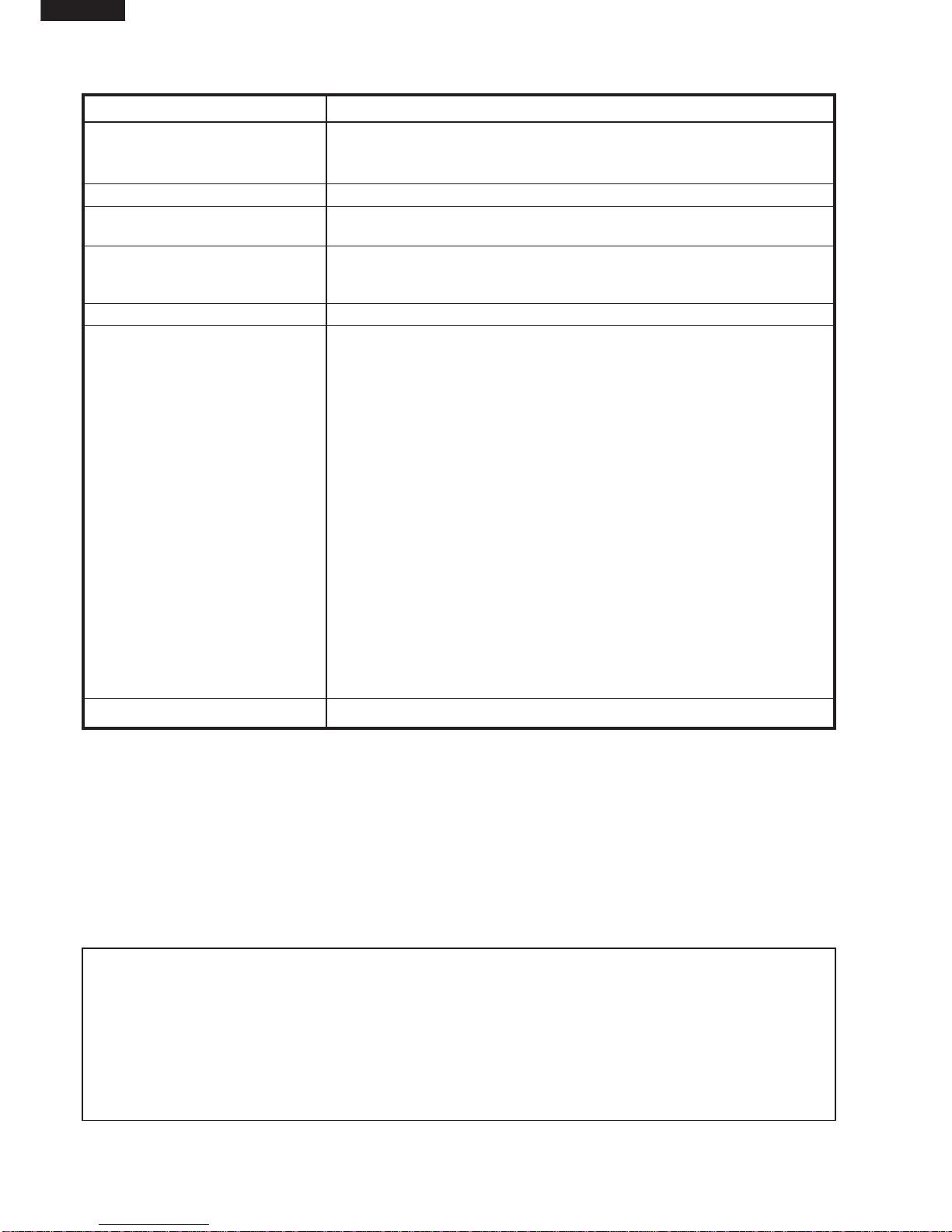
CONNECTED COMPONENTS RELAY
Oven lamp, Fan motor, Turntable motor RY1
Power transformer RY2
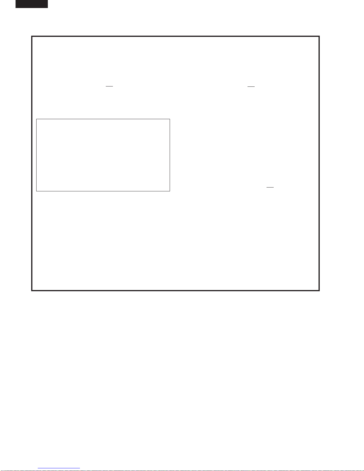
1. Rated voltage is supplied to the primary winding of the
power transformer. The voltage is converted to about
3.3 volts A.C. output on the filament winding and high
voltage of approximately 2000 volts A.C. on the
secondary winding.
2. The filament winding voltage (3.3 volts) heats the
magnetron filament and the high voltage (2000 volts) is
sent to the voltage doubling circuit, where it is doubled
to negative voltage of approximately 4000 volts D.C..
3. The 2450 MHz microwave energy produced in the
magnetron generates a wave length of 12.24 cm. This
energy is channelled through the waveguide (transport
channel) into the oven cavity, where the food is placed
to be cooked.
4. When the cooking time is up, a signal tone is heard and
the relays RY1+RY2 go back to their home position.
The circuits to the oven lamp, power transformer, fan
motor and turntable motor are cut off.
5. When the door is opened during a cook cycle, the
switches come to the following condition
CONDITION
DURING DOOR OPEN
SWITCH CONTACT COOKING
(NOCOOKING)
1st. latch switch COM-NO Closed Open
2nd. interlock relay
control switch COM-NO Closed Open
Monitor switch COM-NC Open Closed
The circuits to the power transformer, fan motor and
turntable motor are cut off when the 1st. latch switch
and 2nd. interlock relay control switch are made open.
The oven lamp remains on even if the oven door is
opened after the cooking cycle has been interrupted,
because the relay RY1 stays closed. Shown in the
display is the remaining time.
6. MONITOR SWITCH CIRCUIT
The monitor switch is mechanically controlled by
oven door, and monitors the operation of the 1st. latch
switch and 2nd. interlock relay.
6-1 When the oven door is opened during or after the
cycle of a cooking program, the 1st. latch switch and
2nd. interlock relay control switch must open their
contacts first.
After that the contacts (COM-NC) of the monitor
switch can be closed.
6-2. When the oven door is closed, the contacts (COM-
NC) of the monitor switch must be opened. After that
the contacts of the 1st. latch switch and 2nd. interlock
relay control switch are closed.
6-3. When the oven door is opened and the contacts of the
1st. latch switch and 2nd. interlock relay remain
closed. The fuse F10A will blow, because the monitor
switch is closed and a short circuit is caused.
MEDIUM HIGH, MEDIUM, MEDIUM LOW, LOW
COOKING
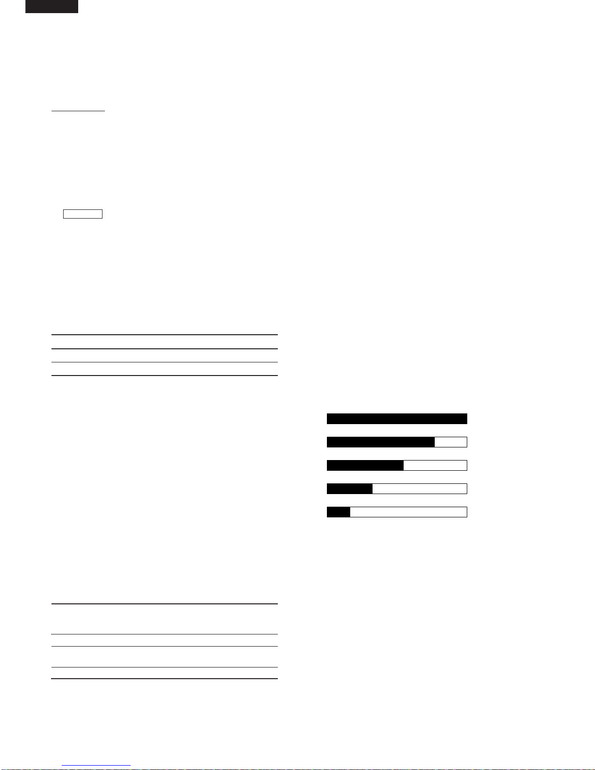
When the microwave oven is preset for variable cooking
power, rated voltage is supplied to the power transformer
intermittently within a 32-second time base through the
relay contact which is coupled with the current-limiting
relay. The following levels of microwave power are given.
SETTING;
NOTE: TheON/OFFtimeratiodoesnotexactlycorrespond
to the percentage of microwave power, because
approx. 3 seconds are needed for heating up the
magnetron filament.
POWER OUTPUT REDUCTION
After 100% power cooking mode is carried out for more
than 40 minutes, the power out-put is automatically re-
duced to 70%.
100P 32 sec. ON
70P Approx. 70%
100%
24 sec. ON 8 sec. OFF
14 sec. OFF
20 sec. OFF
26 sec. OFF
50P Approx. 50%
18 sec. ON
30P Approx. 30%
12 sec. ON
10P Approx. 10%
6 sec. ON

R-330H
5
FUNCTION OF IMPORTANT COMPONENTS
OVEN TEMPERATURE FUSE
The temperature fuse, located on the top of the oven
cavity, is designed to prevent damage to the oven by fire.
If the food load is overcooked, by either error in cook time
or defect in the control unit, the temperature fuse will open.
Under normal operation, the temperature fuse remains
closed. However, when abnormally high temperatures are
reached within the oven cavity, the temperature fuse will
open at 150˚C, causing the oven to shut down.
MAGNETRON TEMPERATURE FUSE
The temperature fuse located near the magnetron is
designed to prevent damage to the magnetron if an over
heated condition develops in the tube due to cooling fan
failure, obstructed air guide, dirty or blocked air intake, etc.
Under normal operation, the temperature fuse remains
closed. However, when abnormally high temperatures are
reached within the magnetron, the temperature fuse will
open at 150˚C causing the oven to shut down.
TURNTABLE MOTOR
The turntable motor drives the turntable roller assembly to
rotate the turntable.
FAN MOTOR
Thefan motor drivesa blade whichdraws external coolair.
This cool air is directed through the air vents surrounding
the magnetron and cools the magnetron. This air is chan-
nelled through the oven cavity to remove steam and
vapours given off from the heating foods. It is then ex-
hausted through the exhausting air vents at the oven
cavity.
NOISE FILTER
The noise filter prevents the radio frequency interference
that might flow back in the power circuit.
DOOR OPEN MECHANISM
he door is opened by pushing the open button on the
control panel, refer to the Figure D-1.
When the open button is pushed, the open button pushes
up the switch lever, and then the switch lever pushes up
the latch head. The latch heads are moved upward and
released from latch hook. Now the door will open.
Figure D-1. Door Open Mechanism
1ST. LATCH SWITCH AND 2ND. INTERLOCK
RELAY CONTROL SWITCH
1. When the oven door is closed, the contacts (COM-NO)
must be closed.
2. When the oven door is opened, the contacts (COM-
NO) must be opened.
MONITOR SWITCH
1. When the oven door is closed, the contacts (COM-NC)
must be opened.
2. When the oven door is opened, the contacts (COM-
NC) must be closed.
3. If the oven door is opened and the contacts (COM-NO)
of the 1st. latch switch and 2nd. interlock relay fail to
open, the fuse F10A blows simultaneously with closing
the contacts (COM-NC) of the monitor switch.
CAUTION: BEFOREREPLACINGABLOWNFUSEF10A
TEST THE 1ST. LATCH SWITCH, 2ND.
INTERLOCK RELAY, MONITOR SWITCH
AND MONITOR RESISTOR FOR PROPER
OPERATION.
HIGH VOLTAGE FUSE
The high voltage fuse blows when the high voltage rectifier
or magnetron is shorted.
FUSE F10A
1. The fuse F10A blows when the contacts (COM-NO) of
the 1st. latch switch and 2nd. interlock relay remain
closed with the oven door open and when the monitor
switch closes.
2. If the wire harness or electrical components are short-
circuited, this fuse F10A blows to prevent an electric
shock or fire hazard.
Latch
Heads
Door
Switch Lever
Latch Hook
Monitor Switch
2nd. Interlock
Relay Control
Switch
1st Latch Switch

R-330H
6
SERVICING
WARNING TO SERVICE PERSONNEL
Microwave ovens contain circuitry capable of producing very high voltage and current, contact with following parts
of the high voltage circuit will result in electrocution. High voltage capacitor, Power transformer, Magnetron, High
voltage rectifier assembly, High voltage fuse, High voltage harness.
REMEMBER TO CHECK 3D
1) Disconnect the supply.
2) Door opened, and wedged open.
3) Discharge the high voltage capacitor.
WARNING: AGAINST THE CHARGE OF THE
HIGH-VOLTAGE CAPACITOR
The high-voltage capacitor remains charged about
60 seconds after the oven has been switched off.
Wait for 60 seconds and then short-circuit the
connection of the high-voltage capacitor (that is, of
the connecting lead of the high-voltage rectifier)
against the chassis with the use of an insulated
screwdriver.
Sharp recommend that wherever possible fault-finding
is carried out with the supply disconnected. It may in,
some cases, be necessary to connect the supply after
the outer case has been removed, in this event carry
out 3D checks and then disconnect the leads to the
primary of the power transformer. Ensure that these
leads remain isolated from other components and the
oven chassis. (Use insulation tape if necessary.) When
the testing is completed carry out 3D checks and
reconnect the leads to the primary of the power trans-
former.
REMEMBER TO CHECK 4R
1) Reconnect all leads removed from components
during testing.
2) Replace the outer case (cabinet).
3) Reconnect the supply.
4) Run the oven. Check all functions.
Microwave ovens should not be run empty. To test for
the presence of microwave energy within a cavity,
place a cup of cold water on the oven turntable, close
the door and set the microwave timer for two (2)
minutes. Set the power level to HIGH and push the
START button. When the two minutes has elapsed
(timer at zero) carefully check that the water is now hot.
If the water remains cold carry out 3D checks and re-
examine the connections to the component being
tested.
When troubleshooting the microwave oven, it is helpful to
follow the Sequence of Operation in performing the
checks. Many of the possible causes of trouble will require
that a specific test be performed. These tests are given a
procedure letter which will be found in the "Test Procedure
"section.
When all service work is completed, and the oven is fully assembled, the microwave power output should be
checked and microwave leakage test should be carried out.
TROUBLESHOOTING GUIDE
IMPORTANT: If the oven becomes inoperative because
of a blown fuse F10A in the 1st. latch
switch-2nd.interlockrelay-monitorswitch
circuit, check the 1st. latch switch, 2nd.
interlock relay and monitor switch before
replacing the fuse F10A.

R-330H
7
MAGNETRON
POWER TRANSFORMER
H.V. RECTIFIER ASSEMBLY
HIGH VOLTAGE CAPACITOR
1ST. LATCH SWITCH
2ND. INTERLOCK RELAY CONTROL
SWITCH
MONITOR SWITCH
TEMPERATURE FUSE (OVEN, MG)
FAN MOTOR
TURNTABLE MOTOR
FUSE F10A
TOUCH CONTROL PANEL
KEY UNIT
RELAY (RY-1, RY-2)
FOIL PATERN ON P.W.B.
POWER SUPPLY CORD
SHORTED WIRE HARNESS
OPENED WIRE HARNESS
OVEN LAMP
WALL OUTLET
MISADJUSTMENT SWITCH
HOME FUSE OR BREAKER
BLOCKED COOLING FAN
BLOCKED VENTILATION
NOISE FILTER
HIGH VOLTAGE FUSE
Homefuse blowswhenpower
supply cord is plugged into
wall outlet.
FUSE F10A blows when
power supply cord is plugged
into wall outlet.
Display does not show any-
thingwhen power supplycord
is plugged into wall outlet.
Display does not operate
properly when STOP/CLEAR
pad is touched.
Oven lamp does not light at
door opened. (Display ap-
pears.)
Oven does not start when the
START pad is touched. (Dis-
play appears)
Ovenlampdoesnotlight(Dis-
play appears.)
Fan motor does not operate.
(Display appears.)
Turntable motor assembly
does not operate. (Display
appears.)
Oven or any electrical parts
does not stop when cooking
time is 0 or STOP/CLEAR
pad is touched.
Oven seems to be operating
butlittleornoheatisproduced
in oven load. (Microwave
power level is set at 100%)
Oven does not seems to be
operatingproperlywhen70%,
50%, 30% or 10% is set.
(Oven operates properly at
100% and then the STOP/
CLEAR pad is touched the
oven stops.)
Oven goes into cook cycle
butshuts down beforeend
of cooking cycle.
TEST PROCEDURE
CK = Check / RE = Replace
ABC
D
EEEFGGHKLMN
RECKCK RE CK CKCK CK CK
IJ
CONDITION PROBLEM
POSSIBLE CAUSE
AND
DEFECTIVE PARTS
ON
CONDITION
OFF
CONDITION

R-330H
8
NEVER TOUCH ANY PART IN THE CIRCUIT WITH YOUR HAND OR AN INSULATED TOOL
WHILE THE OVEN IS IN OPERATION.
CARRY OUT 3D CHECK.
Isolate the magnetron from high voltage circuit by removing all leads connected to filament terminal.
To test for an open circuit filament use an ohmmeter to make a continuity test between the magnetron
filament terminals, the meter should show a reading of less than 1 ohm.
To test for short filament to anode condition, connect ohmmeter between one of the filament terminals
and the case of the magnetron (ground). This test should be indicated an infinite resistance. If a low
or zero resistance reading is obtained then the magnetron should be replaced.
MICROWAVE OUTPUT POWER (1 litre water load)
The following test procedure should be carried out with the microwave oven in a fully assembled
condition (outer case fitted). Microwave output power from the magnetron can be measured by IEC
test procedure, i.e. it can be measured by using water load how much it can be absorbed by the water
load. To measure the microwave output power in the microwave oven, the relation of calorie and watt
is used. When P(W) heating works for t(second), approximately P x t/4.187 calorie is generated. On
the other hand, if the temperature of the water with V(ml) rises ∆T (˚C) during this microwave heating
period, the calorie of the water is V x ∆T.
The formula is as follows;
P x t / 4.187 = V x ∆T+ 0.55 x mc (T2-T0)/4.187
P
(W) = 4.187 x V x ∆T / t + 0.55 x mc (T2-T0)/t
Our condition for water load is as follows:
Room temperature (T0) ... around 20°CPower supply Voltage.............. Rated voltage
Water load..................................1000 g Initial temperature (T1) ...................... 10±1°C
Heating time.............................. 38 sec. Mass of container (mc)......................... 330 g
T2............................ Final Temperature P = 110 x ∆T + 0.55 x mc (T2-T0)/38
Measuring condition:
1. Container
The water container must be a cylindrical borosilicate glass vessel having a maximum material
thickness of 3 mm and an outside diameter of approximately 190 mm.
2. Temperature of the oven and vessel
The oven and the empty vessel are at ambient temperature prior to the start of the test.
3. Temperature of the water
The initial temperature of the water is (10±1)˚C.
4. Select the initial and final water temperature so that the maximum difference between the final
water temperature and the ambient temperature is 5˚C.
5. Select stirring devices and measuring instruments in order to minimize addition or removal of heat.
6. The graduation of the thermometer must be scaled by 0.1˚C at minimum and an accurate
thermometer.
7. The water load must be (1000±5) g.
8. “t” is measured while the microwave generator is operating at full power. Magnetron filament heat-
up time is not included.
NOTE: The operation time of the microwave oven is “t + 3” sec. 3 sec. is magnetron filament heat-
up time.
Measuring method:
1. Measure the initial temperature of the water before the water is added to the vessel.
(Example: The initial temperature T1 = 11˚C)
2. Add the 1 litre water to the vessel.
3. Place the load on the centre of the shelf.
4. Operate the microwave oven at HIGH for the temperature of the water rises by a value ∆T of
10 ˚C.
5. Stir the water to equalize temperature throughout the vessel.
6. Measure the final water temperature. (Example: The final temperature T2 = 21°C)
7. Calculate the microwave power output P in watts from above formula.
TEST PROCEDURES
PROCEDURE
LETTER COMPONENT TEST
AMAGNETRON TEST

R-330H
9
Room temperature .................. To = 21˚C Initial temperature................. T1 = 11°C
Temperature after (38 + 3) = 41 sec. ................................................................ T2 = 21°C
Temperature difference Cold-Warm .............................................................. ∆T1 = 10°C
Measured output power
The equation is “P = 110 x ∆T” ........................................... P = 110 x 10°C = 1100 Watts
TEST PROCEDURES
PROCEDURE
LETTER COMPONENT TEST
JUDGEMENT: The measured output power should be at least ±15 % of the rated output power.
CAUTION: 1°C CORRESPONDS TO 110 WATTS REPEAT MEASUREMENT IF THE POWER IS
INSUFFICIENT.
1000g
1000g
1000g
T1˚CT2˚C
Heat up for 41 sec.
BPOWER TRANSFORMER TEST
WARNING: High voltages and large currents are present at the secondary winding and filament
winding of the power transformer. It is very dangerous to work near this part when
the oven is on. NEVER make any voltage measurements of the high-voltage
circuits, including the magnetron filament.
CARRY OUT 3D CHECKS.
Disconnect the leads to the primary winding of the power transformer. Disconnect the filament and
secondary winding connections from the rest of the HV circuitry. Using an ohmmeter, set on a low
range, it is possible to check the continuity of all three windings. The following readings should be
obtained:
a. Primary winding ....................approx. 1.9 Ω
b. Secondary winding ...............approx. 104 Ω
c. Filament winding...................less than 1Ω
If the reading obtained are not stated as above, then the power transformer is probably faulty and
should be replaced.
CARRY OUT 4R CHECKS.
CHIGH VOLTAGE RECTIFIER ASSEMBLY TEST
HIGH VOLTAGE RECTIFIER TEST
CARRY OUT 3D CHECKS.
Isolate the high voltage rectifier assembly from the HV circuit. The high voltage rectifier can be tested
using an ohmmeter set to its highest range. Connect the ohmmeter across the terminal B+C of the
high voltage rectifier and note the reading obtained. Reverse the meter leads and note this second
reading. The normal resistance is infinite in one direction and more than 100 kΩin the other direction.
CARRY OUT 4R CHECKS.
NOTE: FOR MEASUREMENT OF THE RESISTANCE OF THE RECTIFIER, THE BATTERIES OF
THEMEASURINGINSTRUMENTMUSTHAVEAVOLTAGEATLEAST6VOLTS,BECAUSE
OTHERWISE AN INFINITE RESISTANCE MIGHT BE SHOWN IN BOTH DIRECTIONS.
BC
HIGH VOLTAGE RECTIFIER

R-330H
10
GMOTOR WINDING TEST
TEST PROCEDURES
PROCEDURE
LETTER COMPONENT TEST
DHIGH VOLTAGE CAPACITOR TEST
CARRY OUT 3D CHECKS.
A. Isolate the high voltage capacitor from the circuit.
B. Continuity check must be carried out with measuring instrument which is set to the highest
resistance range.
C. A normal capacitor shows continuity for a short time (kick) and then a resistance of about 10MΩ
after it has been charged.
D. A short-circuited capacitor shows continuity all the time.
E. An open capacitor constantly shows a resistance about 10 MΩbecause of its internal 10MΩ
resistance.
F. When the internal wire is opened in the high voltage capacitor shows an infinite resistance.
G. The resistance across all the terminals and the chassis must be infinite when the capacitor is
normal.
If incorrect reading are obtained, the high voltage capacitor must be replaced.
CARRY OUT 4R CHECKS.
ESWITCH TEST
CARRY OUT 3D CHECKS.
Isolate the switch to be tested and using an ohmmeter check between the terminals as described in
the following table.
Table: Terminal Connection of Switch
Plunger Operation COM to NO COM to NC COM; Common terminal
Released Open circuit Short circuit NO; Normally open terminal
Depressed Short circuit Open circuit NC; Normally close terminal
If incorrect readings are obtained, make the necessary switch adjustment or replace the switch.
CARRY OUT 4R CHECKS.
CARRY OUT 3D CHECKS.
Disconnect the leads from the terminals of the temperature fuse. Then using an ohmmeter, make a
continuity test across the two terminals as described in the table below.
CARRY OUT 4R CHECKS. Table: Temperature fuse Test
Temperature of "ON" condition Temperature of "OFF" condition Indication of ohmmeter
Parts Name (closed circuit) (˚C) (open circuit) (˚C) (When room temperature
is approx. 20˚C)
Temperature fuse 150˚C This is not resetable type. Above 150˚C Closed circuit.
If incorrect readings are obtained, replace the temperature fuse.
An open circuit temperature fuse (MG) indicates that the magnetron has overheated, this may be due
to resistricted ventilation, cooling fan failure or a fault condition within the magnetron or HV circuit.
An open circuit temperature fuse (OVEN) indicates that the foods in the oven may catch fire, this may
be due to over heating produced by improper setting of the cooking time or failure of the control panel.
FTEMPERATURE FUSE TEST
CARRY OUT 3D CHECKS.
Disconnect the leads from the motor.
Using an ohmmeter, check the resistance between the two terminals as described in the table below.

R-330H
11
TEST PROCEDURES
PROCEDURE
LETTER COMPONENT TEST
Table: Resistance of Motor
Motors Resistance
Fan motor Approximately 250 Ω
Turntable motor Approximately 14.5 kΩ
If incorrect readings are obtained, replace the motor.
CARRY OUT 4R CHECKS
CARRY OUT 3D CHECKS.
1. If the fuse F10A is blown, there could be shorts or ground in electrical parts or wire harness.
Check them and replace the defective parts or repair the wire harness.
2. If the fuse F10A is blown when the door is opened, check the 1st. latch switch, 2nd. interlock relay
and monitor switch.
If the fuse F10A is blown by incorrect door switching replace the defective switch(s) and the fuse
F10A.
CARRY OUT 4R CHECKS.
CAUTION: ONLY REPLACE FUSE F10A WITH THE CORRECT VALUE REPLACEMENT
H BLOWN FUSE F10A
INOISE FILTER TEST
CARRY OUT 3D CHECKS.
Disconnect the leads from the terminals of the noise
filter. Using an ohmmeter, check between the termi-
nals as described in the following table.
MEASURING POINT INDICATION OF
OHMMETER
Between N and L Open circuit
Between terminal N and WHITE Short circuit
Between terminal L and RED Short circuit
If incorrect readings are obtained, replace the noise filter unit.
CARRY OUT 4R CHECKS.
CARRY OUT 3D CHECKS.
If the high voltage fuse is blown, there could be a short in the high voltage rectifier or the magnetron.
Check them and replace the defective parts and high voltage fuse.
CARRY OUT 4R CHECKS.
CAUTION: ONLY REPLACE THE HIGH VOLTAGE FUSE WITH THE CORRECT VALUE RE-
PLACEMENT
JHIGH VOLTAGE FUSE TEST
KTOUCH CONTROL PANEL ASSEMBLY TEST
The touch control panel consists of circuits including semiconductors such as LSI, ICs, etc. Therefore,
unlike conventional microwave ovens, proper maintenance cannot be performed with only a
voltmeter and ohmmeter. In this service manual, the touch control panel assembly is divided into two
units, Control Unit and Key Unit, and also the Control Unit is divided into two units, CPU Unit and
Power Unit, and troubleshooting by unit replacement is described according to the symptoms
indicated.
RED
WHT
FUSE
F10A
NL
LINE CROSS CAPACITOR
0.068µ/AC250V
NOISE SUPPRESSION COIL
LINE BYPASS CAPACITOR
0.0022µ/AC250V LINE BYPASS CAPACITOR
0.0022µ/AC250V

R-330H
12
MRELAY TEST
TEST PROCEDURES
PROCEDURE
LETTER COMPONENT TEST
LKEY UNIT TEST
1, CARRY OUT 3D CHECKS.
2. Isolate the key unit with the control panel frame to be tested.
3. Using an ohmmeter and referring to the key unit matrix indicated on the control unit circuit, check
the circuit between the pins of the key unit that correspond to the STOP/CLEAR pad. When the
pad is pressed, the ohmmeter should indicate short circuit. When the pad is released, the
ohmmeter should indicate open circuit. If incorrect readings are obtained, the key unit is faulty and
must be replaced. About the other pads, the above method may be used.
4. CARRY OUT 4R CHECKS.
1. Key Unit. Note: Check key unit ribbon connection before replacement.
The following symptoms indicate a defective key unit. Replace the control unit assembly.
a) When touching the pads, a certain pad produces no signal at all.
b) When touching a number pad, two figures or more are displayed.
c) When touching the pads, sometimes a pad produces no signal.
2. Control Unit.
The following symptoms indicate a defective control unit. Before replacing the control unit, perform
the Key unit test (Procedure L) to determine if control unit is faulty.
2-1 In connection with pads.
a) When touching the pads, a certain group of pads do not produce a signal.
b) When touching the pads, no pads produce a signal.
2-2 In connection with indicators.
a) At a certain digit, all or some segments do not light up.
b) At a certain digit, brightness is low.
c) Only one indicator does not light.
d) The corresponding segments of all digits do not light up; or they continue to light up.
e) Wrong figure appears.
f) A certain group of indicators do not light up.
g) The figure of all digits flicker.
2-3 Other possible troubles caused by defective control unit.
a) Buzzer does not sound or continues to sound.
b) Clock does not operate properly.
c) Cooking is not possible.
Remove the outer case and check voltage between the normal open terminal of the relay RY1 and
the normal open terminal of the relay RY2 on the power unit with an A.C. voltmeter. The meter should
indicate 230 - 240 volts, if not check oven circuit.
INSTANT COOK
START
G6 G7 G8G3
G10
G11
G12
G4 G5
G9
G2G1
4
7
5
8
91
3
6
2
0
EASY
DEFROST
EXPRESS
DEFROST
TIMER
CLOCK
STOP
CLEAR
POWER
LEVEL
JACKET
POTATO
DINNER
PLATE
FROZEN
VEGETABLES
FRESH
VEGETABLES
PIE
PIZZA
RICE-PASTA
BEVERAGE
Pin
NO. G12 Pin
NO. G1
Key unit ribbon cable
Key unit (Membrane Switch) front view

R-330H
13
o protect the electronic circuits, this model is provided with a fine foil pattern added to the primary on
the PWB, this foil pattern acts as a fuse. If the foil pattern is open, follow the troubleshooting guide
given below for repair.
Problem: POWER ON, indicator does not light up.
CARRY OUT 3D CHECKS.
STEPS OCCURRENCE CAUSE OR CORRECTION
1 The rated AC voltage is not present between Check supply voltage and oven power cord.
the normal open terminal of the relay RY1
and the normal open terminal of the relay RY2.
2 The rated AC voltage is present to primary Low voltage transformer or secondary circuit defective.
side of low voltage transformer. Check and replace control unit assembly.
3Only pattern at "a" is broken. *Insert jumper wire J1 and solder.
4 Pattern at "a" and "b" are broken. *Insert the coil RCILF2003YAZZ between "c" and "d".
NOTE: *At the time of making these repairs, make a
visualinspectionofthevaristor.Checkforburned
damage and examine the transformer with a
tester for the presence of layer short-circuit
(check the primary coil resistance). If any
abnormal condition is detected, replace the
control unit assembly.
CARRY OUT 4R CHECKS.
TEST PROCEDURES
PROCEDURE
LETTER COMPONENT TEST
N PROCEDURES TO BE TAKEN WHEN THE FOIL PATTERN ON THE PRINTED WIRING BOARD
(PWB) IS OPEN
RY1 and RY2 Relay Test
These relays are operated by D.C. voltage.
Check voltage at the relay coil with a D.C. voltmeter during the microwave cooking operation.
DC. voltage indicated............... Defective relay.
DC. voltage not indicated......... Check diode which is connected to the relay coil. If diode is good,
control unit is defective.
RELAY SYMBOL OPERATIONAL VOLTAGE CONNECTED COMPONENTS
RY1 APPROX. -11.8V D.C. Oven lamp / Turntable motor / Cooling fan motor
RY2 APPROX. -10.5V D.C. Power transformer
CARRY OUT 4R CHECKS.
d
ab
c

R-330H
14
TOUCH CONTROL PANEL ASSEMBLY
OUTLINE OF TOUCH CONTROL PANEL
The touch control section consists of the following units.
(1) Key Unit
(2) Control Unit (The Control Unit consists of Power Unit
and CPU Unit).
The principal functions of these units and the signals
communicated among them are explained below.
Key Unit
The key unit is composed of a matrix, signals generated
in the LSI are sent to the key unit through P22, P23, P24,
P25, P26, P31, P32 and P33.
When a key pad is touched, a signal is completed through
the key unit and passed back to the LSI through P50, P51,
P52 and P53 to perform the function that was requested.
Control Unit
Control unit consists of LSI, reset circuit, indicator circuit,
power source circuit, relay circuit, buzzer circuit, synchro-
nizing signal circuit and back light circuit.
1) Reset Circuit
This circuit generates a signal which resets the LSI to
the initial state when power is supplied.
2) Indicator Circuit
This circuit consists of 14 segments and 3 common
electrodes using a Liquid Crystal Display.
3) Power Source Circuit
This circuit generates voltages necessary in the control
unit from the AC line voltage.
In addition, the synchronizing signal is available in
order to compose a basic standard time in the clock
circuit.
Symbol Voltage Application
VSS -5V LSI(IC1)
4) Relay Circuit
A circuit to drive the magnetron, fan motor, turntable
motor and light the oven lamp.
5) Buzzer Circuit
Thebuzzer is responsiveto signals fromthe LSI toemit
audible sounds (key touch sound and completion
sound).
6) Synchronizing Signal Circuit
The power source synchronizing signal is available in
order to compose a basic standard time in the clock
circuit.
It accompanies a very small error because it works on
commercial frequency.
7) 2nd. Interlock Relay Control Switch
A switch to “tell” the LSI if the door is open or closed.
8) Back Light Circuit
A circuit to drive the back light (Light emitting diodes
LD1- LD3).

R-330H
15
1P50 IN Signal coming from touch key.
When either G9 line on key matrix is touched, a corresponding signal out of P22 - P26 and
P31 - P33 will be input into P50. When no key is touched, the signal is held at “H” level.
2P51 IN Signal similar to P50.
When either G10 line on key matrix is touched, a corresponding signal will be input into
P51.
3P52 IN Signal similar to P50.
When either G11 line on key matrix is touched, a corresponding signal will be input into
P52.
4P53 IN Signal similar to P50.
When either G12 line on key matrix is touched, a corresponding signal will be input into
P53.
5ICINConnected to VSS.
6XT1 IN Connected to VSS.
7XT2 _ Terminal not used.
8VDD IN Power source voltage input terminal.
The power souce voltage to drive the LSI. Connected to GND.
9VSS IN Power source voltage input terminal.
The power souce voltage to drive the LSI.
10 X1 IN Internal clock oscillation frequency input setting.
The internal clock frequency is set by inserting the resistor-capacitor oscillation circuit with
respect to X2 terminal.
11 X2 OUT Internal clock oscillation frequency control output.
Output to control oscillation input of X1.
12 RESET IN Auto clear terminal.
Signal is input to reset the LSI to the initial state when power is applied.
13-15 P00-P02 OUT Terminal not used.
16 P03 OUT Back light circuit (Light emitting diodes) driving signal.
17 CAPH _ Terminal not used.
18 CAPL _ Terminal not used.
19-21
VLC0-VLC2
IN Power source voltage input terminal.
Standard voltage for LCD.
22 COM0 OUT Common data signal.
Connected to LCD signal COM1.
23 COM1 OUT Common data signal.
Connected to LCD signal COM2.
24 COM2 OUT Common data signal.
Connected to LCD signal COM3.
25 COM3 OUT Terminal not used.
26-39
SEG0-SEG13
OUT Segment data signal.
Connected to LCD.
The relation between signals are as follows:
LSI signal (Pin No.) LCD (segment) LSI signal (Pin No.) LCD (segment)
SEG 0 (26) ................................... SEG 1 SEG 7 (33) ................................SEG 8
SEG 1 (27) ................................... SEG 2 SEG 8 (34) ................................SEG 9
SEG 2 (28) ................................... SEG 3 SEG 9 (35) ..............................SEG 10
SEG 3 (29) ................................... SEG 4 SEG 10 (36) ..............................SEG 11
SEG 4 (30) ................................... SEG 5 SEG 11 (37) ..............................SEG 12
SEG 5 (31) ................................... SEG 6 SEG 12 (38) ..............................SEG 13
SEG 6 (32) ................................... SEG 7 SEG 13 (39) ..............................SEG 14
40 SEG14 OUT Terminal not used.
41 P70 OUT Oven lamp, fan motor and turntable motor driving signal
To turn on and off shut off relay (RY1). The
square waveform voltage is delivered to the
RY1 driving circuit and RY2 control circuit.
42 P71 OUT Terminal not used.
LSI
The I/O signal of the LSI is detailed in the following table.
Pin No. Signal I/O Description
20 msec.
During cooking
H : GND
L : -5V

R-330H
16
43 P72 OUT Magnetron high-voltage circuit driving signal.
To turn on and off the cook relay (RY2). The
signals holds “L” level during microwave cook-
ing and “H” level while not cooking. In other
cooking modes (variable cooking) the signal
turns to “H” level and “L” level in repetition
according to the power level.
44 AVDD IN A/D converter power source voltage.
The power source voltage to drive the A/D converter in the LSI. Connected to GND.
45-48 AIN5-AIN2 IN Terminal to change cooking input according to the Model.
By using the A/D converter contained in the LSI, DC voltage in accordance with the Model
in operation is applied to set up its cooking constant.
49 AIN1 IN This is the terminal to detect the voltage of the signal coming from the touch key.
50 AIN0 IN Signal similar to AIN1.
51 AVSS IN A/D converter power source voltage.
The power source voltage to drive the A/D converter in the LSI.
52 P11 IN To input signal which communicates the door open/close information to LSI.
Door close “H” level signal (0V). Door open “L” level signal (-5V).
53 P10 OUT Terminal not used.
54 P33 OUT Key strobe signal.
Signal applied to touch-key section. A pulse signal is input to P50, P51, P52 and P53
terminal while one of G1 line keys on key matrix is touched.
55 P32 OUT Key strobe signal.
Signal applied to touch-key section. A pulse signal is input to P50, P51, P52 and P53
terminal while one of G2 line keys on key matrix is touched.
56 P31 OUT Key strobe signal.
Signal applied to touch-key section. A pulse signal is input to P50, P51, P52 and P53
terminal while one of G3 line keys on key matrix is touched.
57 INTP0 IN Signal synchronized with commercial power source frequency.
This is the basic timing for time processing of LSI.
58 P26 OUT Key strobe signal.
Signal applied to touch-key section. A pulse signal is input to P50, P51, P52 and P53
terminal while one of G4 line keys on key matrix is touched.
59 P25 OUT Key strobe signal.
Signal applied to touch-key section. A pulse signal is input to P50, P51, P52 and P53
terminal while one of G5 line keys on key matrix is touched.
60 P24 OUT Key strobe signal.
Signal applied to touch-key section. A pulse signal is input to P50, P51, P52 and P53
terminal while one of G6 line keys on key matrix is touched.
61 P23 OUT Key strobe signal.
Signal applied to touch-key section. A pulse signal is input to P50, P51, P52 and P53
terminal while one of G7 line keys on key matrix is touched.
62 P22 OUT Key strobe signal.
Signal applied to touch-key section. A pulse signal is input to P50, P51, P52 and P53
terminal while one of G8 line keys on key matrix is touched.
63 BZO90 OUT Signal to sound buzzer (2.0 kHz).
A: key touch sound.
B: Completion sound.
64 P20 OUT Terminal not used.
Pin No. Signal I/O Description
Maximum
output
70% of maximum
output
H : GND
L : -5V
H : GND
L : -5V
ON
ON
OFF
OFF OFF
24 sec.
8 sec.
20 msec.
H : GND
L : -5V
A
B
0.1 sec.
2.0 sec.
H : GND
L : -5V
H : GND
L : -5V

R-330H
17
1. Precautions for Handling Electronic Components
This unit uses CMOS LSI in the integral part of the circuits.
Whenhandlingtheseparts,thefollowingprecautionsshould
be strictly followed. CMOS LSI have extremely high
impedanceat its inputandoutput terminals. Forthisreason,
itis easily influenced by the surrounding high voltage power
source,staticelectricitychargeinclothes,etc.andsometimes
it is not fully protected by the built-in protection circuit.
In order to protect CMOS LSI.
1) When storing and transporting, thoroughly wrap them in
aluminium foil. Also wrap all PW boards containing them
in aluminium foil.
2) When soldering, ground the technician as shown in the
figure and use grounded soldering iron and work table.
2. Servicing of Touch Control Panel
Wedescribetheprocedures to permit servicing of the touch
control panel of the microwave oven and the precautions
you must take when doing so. To perform the servicing,
power to the touch control panel is available either from the
power line of the oven itself or from an external power
source.
(1) Servicing the touch control panel with power supply
of the oven:
CAUTION:
THE HIGH VOLTAGE TRANSFORMER OF THE
MICROWAVE OVEN IS STILL LIVE DURING
SERVICING AND PRESENTS A HAZARD.
Therefore, before checking the performance of the touch
control panel,
1) Disconnect the power supply cord, and then remove
outer case.
2) Open the door and block it open.
3) Discharge high voltage capacitor.
4) Disconnect the leads to the primary of the power
transformer.
5) Ensure that these leads remain isolated from other
components and oven chassis by using insulation
tape.
6) After that procedure, re-connect the power supply
cord.
After checking the performance of the touch control panel,
1) Disconnect the power supply cord.
2) Open the door and block it open.
3) Re-connect the leads to the primary of the power
transformer.
4) Re-install the outer case (cabinet).
5) Re-connect the power supply cord after the outer
case is installed.
6) Run the oven and check all functions.
approx. 1M ohm
TOUCH CONTROL PANEL SERVICING
A. On some models, the power supply cord between the
touch control panel and the oven itself is so short that the
two can’t be separated. For those models, check and
repair all the controls (sensor-related ones included) of
the touch control panel while keeping it connected to the
oven.
B. On some models, the power supply cord between the
touch control panel and the oven proper is long enough
that they may be separated from each other. For those
models, it is possible to check and repair the controls of
the touch control panel while keeping it apart from the
oven proper; in this case you must short both ends of the
door sensing switch (on PWB) of the touch control panel
with a jumper, which activates an operational state that is
equivalent to the oven door being closed. As for the
sensor-relatedcontrolsofthetouchcontrolpanel,checking
them is possible if dummy resistor(s) with resistance
equal to that of the controls are used.
(2) Servicing the touch control panel with power supply
from an external power source:
Disconnect the touch control panel completely from the
oven proper, and short both ends of the door sensing
switch(onPWB)ofthetouchcontrolpanel,whichactivates
an operational state that is equivalent to the oven door
being closed. Connect an external power source to the
power input terminal of the touch control panel, then it is
possible to check and repair the controls of the touch
control panel it is also possible to check the sensor-
related controls of the touch control panel by using the
dummy resistor(s).
3. Servicing Tools
Toolsrequiredtoservicethetouchcontrolpanelassembly.
1) Soldering iron: 30W
(Itisrecommendedtouseasolderingironwithagrounding
terminal.)
2) Oscilloscope: Single beam, frequency range: DC-10MHz
type or more advanced model.
3) Others: Hand tools
4. Other Precautions
1) Before turning on the power source of the control unit,
remove the aluminium foil applied for preventing static
electricity.
2) Connect the connectors of the key unit to the control unit
being sure that the lead wires are not twisted.
3) After aluminium foil is removed, be careful that abnormal
voltage due to static electricity etc. is not applied to the
input or output terminals.
4) Attach connectors, electrolytic capacitors, etc. to PWB,
making sure that all connections are tight.
5) Besure touse specifiedcomponents wherehigh precision
is required.

R-330H
18
PRECAUTIONS FOR USING LEAD-FREE SOLDER
1. Employing lead-free solder
The "Main PWB" of this model employs lead-free solder. This is indicated by the "LF" symbol printed on the PWB
and in the service manual. The suffix letter indicates the alloy type of the solder.
Example:
Indicates lead-free solder of tin, silver and copper.
2. Using lead-free wire solder
When repairing a PWB with the "LF" symbol, only lead-free solder should be used. (Using normal tin/lead alloy solder
may result in cold soldered joints and damage to printed patterns.)
As the melting point of lead-free solder is approximately 40˚C higher than tin/lead alloy solder, it is recommend that
a dedicated bit is used, and that the iron temperature is adjusted accordingly.
3. Soldering
As the melting point of lead-free solder (Sn-Ag-Cu) is higher and has poorer wettability, (flow), to prevent damage
to the land of the PWB, extreme care should be taken not to leave the bit in contact with the PWB for an extended
period of time. Remove the bit as soon as a good flow is achieved. The high content of tin in lead free solder will cause
premature corrosion of the bit. To reduce wear on the bit, reduce the temperature or turn off the iron when it is not
required.
Leaving different types of solder on the bit will cause contamination of the different alloys, which will alter their
characteristics, making good soldering more difficult. It will be necessary to clean and replace bits more often when
using lead-free solder. To reduce bit wear, care should be taken to clean the bit thoroughly after each use.
Sn-Ag-Cu
Table of contents
Other Sharp Microwave Oven manuals

Sharp
Sharp Carousel R-308H User manual

Sharp
Sharp R-231NW User manual

Sharp
Sharp Carousel R-1502 User manual

Sharp
Sharp R-202EW User manual

Sharp
Sharp R-350A User manual

Sharp
Sharp R-86STM-A Instruction Manual

Sharp
Sharp YC-MG02E-S User manual

Sharp
Sharp SMD2470ASY User manual

Sharp
Sharp YC-MS02U User manual

Sharp
Sharp R-508HS User manual

Sharp
Sharp R-1380 User manual

Sharp
Sharp R-290H User manual

Sharp
Sharp YC-PS201A User manual

Sharp
Sharp Carousel R-480J User manual

Sharp
Sharp R-340DK User manual

Sharp
Sharp R-242M Instruction Manual

Sharp
Sharp R-530EK-T User manual

Sharp
Sharp R-212B User manual

Sharp
Sharp R-879 Instruction Manual

Sharp
Sharp R-8000E User manual