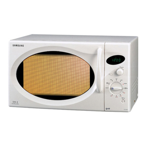
R-950A
38
Note: The parts marked "∆" may cause undue microwave exposure.
The parts marked "*" are used in voltage more than 250V.
REF. NO. PART NO. DESCRIPTION Q'TY CODE
∆
Q20-23 VSKRA101M//-3 Transistor (KRA101M) 4 AB
Q24-25 VSKRA223M//-3 Transistor (KRA223M) 2 AB
Q26 VSKRC243M//-3 Transistor (KRC243M) 1 AB
Q27 VSKRA223M//-3 Transistor (KRA223M) 1 AB
Q40 VSKRA101M//-3 Transistor (KRA101M) 1 AB
Q60 VSKRC101M//-3 Transistor (KRC101M) 1 AB
Q90-91 VSKRA101M//-3 Transistor (KRA101M) 2 AB
R3-4 VRS-B13AA471J Resistor 470 ohm 1W 2 AA
R7-8 VRD-B12EF472J Resistor 4.7k ohm 1/4W 2 AA
R10-11 VRS-B13AA180J Resistor 18 ohm 1W 2 AA
R30 VRD-B12EF153J Resistor 15k ohm 1/4W 1 AA
R31 VRD-B12EF472J Resistor 4.7k ohm 1/4W 1 AA
R40 VRD-B12EF332J Resistor 3.3k ohm 1/4W 1 AA
R50 VRD-B12EF153J Resistor 15k ohm 1/4W 1 AA
R51 VRD-B12EF472J Resistor 4.7k ohm 1/4W 1 AA
R62 VRN-B12EK753F Resistor 75k ohm(F) 1/4W 1 AA
R63 VRN-B12EK101F Resistor 100 ohm(F) 1/4W 1 AA
R64 VRN-B12EK222F Resistor 2.2k ohm(F) 1/4W 1 AA
R70-81 VRD-B12EF332J Resistor 3.3k ohm 1/4W 12 AA
R90-94 VRD-B12EF104J Resistor 100k ohm 1/4W 5 AA
RY1-3 RRLY-A083DRE0 Relay (OMIF-S-118LM) 3 AK
RY4-6 RRLY-A078DRE0 Relay (OJ-SS-118LM) 3 AG
RY7 RRLY-A083DRE0 Relay (OMIF-S-118LM) 1 AK
SP40 RALM-A014DRE0 Buzzer (PKM22EPT) 1 AG
T1 RTRNPA089DRE0 Transformer 1 AU
VRS1 RH-VZA032DRE0 Varistor (10G471K) 1 AE
ZD3 VHEHZ5C2///-1 Zener diode (HZ5C-2) 1 AA
ZD4 VHEHZ4A2///-1 Zener diode (HZ4A2) 1 AA
3- 2 DPNLCB460WRK0 Control panel frame with key unit 1 BE
3- 2-1 FUNTKA836WRE0 Key unit 1 BA
3- 2-2 JBTN-B060WRF0 Open button 1 AF
3- 2-3 MSPRCA050WRE0 Open button spring 1 AB
3- 3 LANGTA340WRW0 Control panel back plate 1 AK
3- 4 MLEVFA057WRW0 Open lever 1 AE
3- 5 NSFTTA042WRE0 Open shaft 1 AE
3- 6 XEPSD30P10XS0 Screw ; control unit mtg. 3 AA
3- 7 XCPSD40P12000 Screw ; control panel back plate mtg. 2 AA
OVEN PARTS
4- 1 FOVN-A402WRY0 Oven cavity assembly 1 BV
4- 2 FROLPA072WRK0 Turntable support 1 AL
4- 3 NTNT-A019WRH0 Turntable tray 1 AT
4- 4 FBRGMA002WRE0 Bearing ass’y 1 AQ
4- 5 PREFHA028WRW0 Thermal protection plate (left) 1 AR
4- 6 LANGTA196WRW0 Bearing mounting plate 1 AD
4- 7 LBNDK0054WRE0 Heater element holder 2 AB
4- 8 LFIX-A013WRW0 Bearing holder plate 1 AB
4- 9 NFANMA019WRW0 Convection fan 1 AE
4-10 NPLYBA025WRF0 Pulley (F) 2 AC
4-11 FDUC-A279WRK0 Heater duct assembly 1 AT
4-12 PFPF-A138WRE0 Thermal protection sheet (left) 1 AK
4-13 LANGQA410WRP0 Thermal cut-out mounting plate 1 AG
4-14 PCUSUA167WRP0 Cushion 2 AF
4-15 PCUSUA424WRP0 Cushion 1 AG
4-16 PDUC-A680WRW0 Steam duct assembly 1 AY
4-17 MCAMPA030WRF0 Damper cam 1 AC
4-18 NSFTTA114WRE0 Damper shaft 1 AB
4-19 FFTA-A034WRK0 Damper door ass’y 1 AM
4-20 PDUC-A269WRW0 Damper duct 1 AK
4-21 PCUSGA410WRP0 Cushion 1 AD
4-22 NCPL-A021WRF0 Turntable coupling 1 AE
4-23 PCOVPA301WRE0 Waveguide cover 1 AE
4-24 PCUSUA197WRP0 Cushion 2 AD
4-25 PGLSPA485WRE0 Light glass 1 AF
4-26 PFPF-A139WRE0 Thermal protection sheet (Right) 1 AF
4-27 PREFHA053WRW0 Thermal protection plate (Right) 1 AP
4-28 PSKR-A153WRW0 Air guide (Bottom) 1 AK
4-29 PSKR-A329WRW0 Divide plate (Right) 1 AM
4-30 LANGQA407WRW0 Convection motor mounting plate 1 AG
4-31 LANGQA369WRP0 Thermal cut-out mounting angle 1 AC
4-32 NFANJA020WRE0 Fan blade 1 AE
4-33 PDUC-A270WRF0 Cooling fan duct 1 AL
4-34 LANGFA089WRW0 Chassis support 1 AE
4-35 MHNG-A165WRM0 Oven hinge (Upper) 1 AE
4-36 NBLTKA005WRE0 Convection fan belt 1 AF
4-37 LANGQA475WRP0 Noise unit angle 1 AR
∆
