MECHANICAL ADJUSTMENT
Except for the following item, refer to the
RD620X
Service
Manual already issued.
n
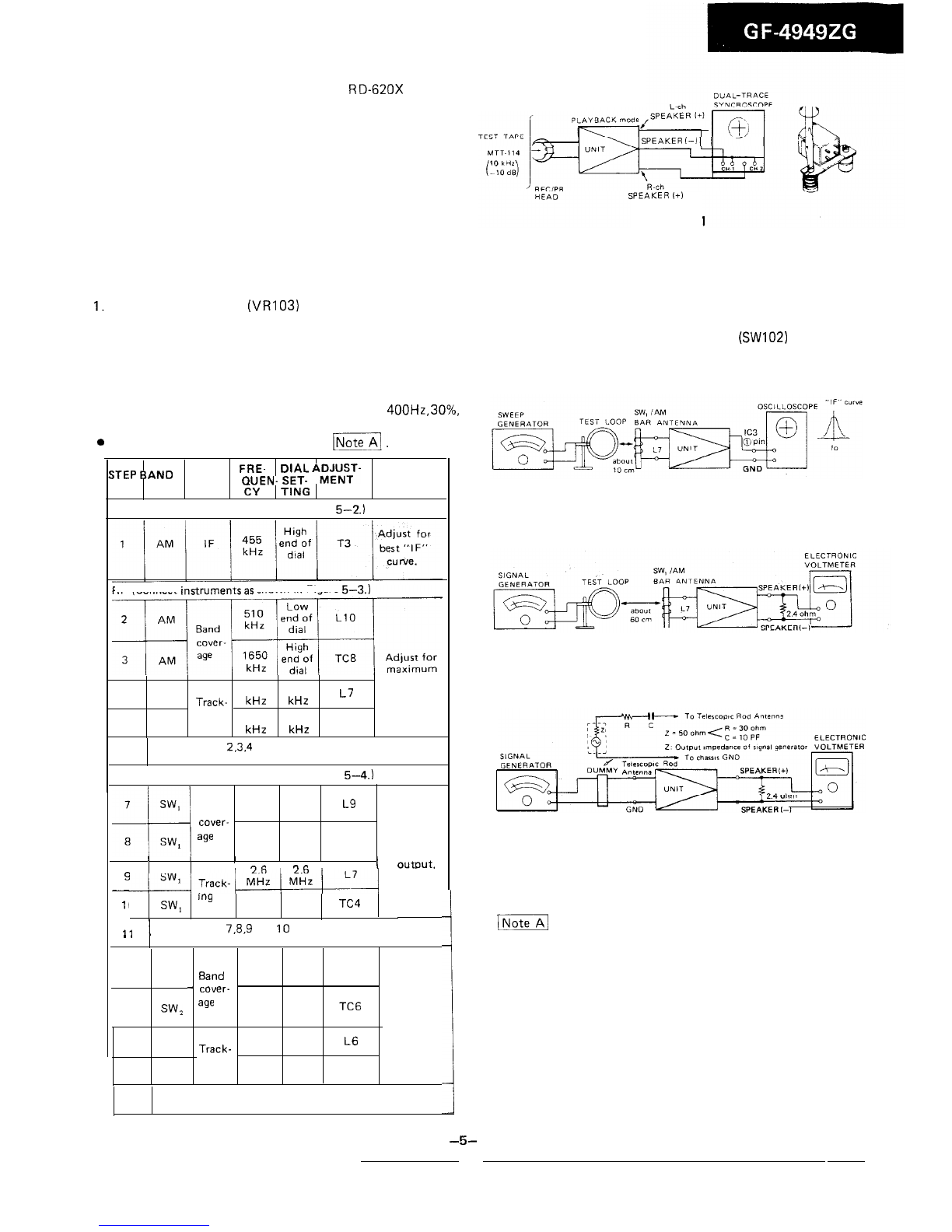
RECORD/PLAYBACK HEAD AZIMUTH ADJUSTMENT
As shown in Figure 5-1, connect instruments, and adjust
the head azimuth adjusting screw so that the output signals
from both channels will have maximum waveform with the
same phase in right and left.
SPEAKER
f-1
SPEAKER
(+I
Figure 5-l
GENERAL ALIGNMENT INSTRUCTION
Should it become necessary at any time to check the alignment of this receiver, proceed as follows;
1.
Set the volume control
(VR103)
to maximum.
2. Attenuate the signals from the generator enough to swing
the most sensitive range of the output meter.
3. Use a non-metallic alignment tool.
4. Repeat adjustments to insure good results.
5. Set the Function Selector Switch (SW102) to “radio”
position.
AM IF/RF ALIGNMENT
l
Set the signal generator to produce a signal of
400Hz,
30%,
AM modulated.
0For adjustments in steps 4 and 9, see
-1.
E
TEST FRE-
‘TEP
BAND
STAGE
QUEN-
SET-
D’AL
A;;\y-
REMARKS
CY
TING
IF
(Connect instruments as shown in Figure
5-2.)
RF (Connect
instrumentsas
shown in Figure
5-3.)
4
output.
AM
600
600
kHz kHz
L7
Track-
5
AM
ing
1400 1400
kHz kHz
TC5
6
Repeat steps
2.3.4
and 5 until no further Improvement
can be made.
RF (Connect instruments as shown in Figure
5-4.)
2.25
LOW
Band MHz end of
L9
dial
cover-
age
7.4 High
end of TC7
MHz Adjust for
dial maximum
/I
“A
n,.
I
OUtDUt.
c
-
11
0
SW,
w
6.0 6.0
MHz MHZ TC4
11
1
Repeat steps
7.8.9
and 10 until no further improvement
,
.
can be made.
7.2 Low
12 SW, MHz end of La
Band dial
-
cover- 22.5 High
13 SW,
age
end of TC6 Adjust for
MHz dial maximum
a.5 a.5 output.
14 SW, MHz MHz
L6
Track-
15 SW,
ing
19
19
MHz MHz TC3
16 Repeat steps 12, 13, 14 and 15 until no further impro-
vement can be made.
1
1
-5-
Figure 5-2
Figure 5-3
Figure 5-4
1-1
Check the alignment of the receiver antenna coil by
bringing a piece of ferrite (such as a coil slug) near the antenna
loop stick, then a piece of brass. If ferrite increases output,
loop requires more inductance. If brass increases output, loop
requires less inductance. Change loop inductance by sliding the
bobbin toward the center of the ferrite core to increase induct-
ance, or away to decrease inductance.


 User manual")


 User manual")
/(W) User manual")