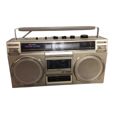
Sharp JG545X(GY) User manual

SHARP
SERVICE
MANUAL
S9381 JC545XGY
JG545X(GY)
l
In the interests of user-safety the set should be restored to its original
condition and only parts identical to those specified be used.
INDEX
TO
CONTENTS
Page
SPECIFICATIONS..
..
.............................................................................................................
2
NAMES OF PARTS
........................... ....................................................................................
2
DISASSEMBLY.. ....................................................................................................................
3
REMOVING AND REINSTALLING THE MAIN PARTS.........................................................
4
ADJUSTMENT .......................................................................................................................
5
NOTES ON SCHEMATIC DIAGRAM ....................................................................................
6
TYPES OF TRANSISTOR AND
LED
...................... ...............................................................
6
FITING
OF DIAL POINTER ...............................
.
.
...................................................................
6
EXPLODED VIEW
......................................... ....................................................................
7,
a
SCHEMATIC
DIAGRAM
/WIRING
SIDE OF P.W.BOARD
.............................................
9-12
REPLACEMENT PARTS LIST
.......................................................................................
13-15
SHARP
CORPORATION

FOR A COMPLETE DESCRIPTION OF THE OPERATION OF THIS UNIT, PLEASE REFER
TO THE OPERATION MANUAL.
SPECIFICATIONS
General Tape deck
Power source:
Output power:
DC 3 V[“AA”size
(UM/SUM-3,
R6
or
HP-7) battery
x
2 or external DC 3 V]
Max;20mW(10mW+10mW)
(DC operation)
Dimension:
Weight:
RMS;
10
mW
(5
mW
+
5mW)
(DC operation, 10
%
T
.H.D)
Width;
61
mm
(3-3116”)
Height; 117 mm
(4-9/l
6”)
Depth; 29.9 mm
(1
-l/8”)
185
g
(6.5 oz.) without batteries
Frequency response:
40
-
15,000 Hz
(MetaKrOJNormal
tape)
Radio
Frequency range:
FM
;
aa
-
108
MHZ
AM; 526.5
-
1,606.5
kHz
Headphones
Type:
Impedance:
Inner-ear dynamic
24 ohms
Specifications for this model are subject to change without
prior notice.
NAMES
OF
PARTS
1. Power/Battery Indicator
2. Extra Bass Switch: X-BASS
3. Volume Control
4. FunctionTape Selector switch
5.
Headphones Socket
6.
Tape Direction Switch: 41,
7. Stop Button:
q
8.
Fast Wind Buttons:
t(
/
w
9.
Play Botton:
0
10. External DC Power Input Socket
Il.
Tuning Control
12. Band Selector Switch
13.
Cassette Compartment
14.
Battery Compartment
15.
Headphones
1
2345
\
\
\
Figure
2-l
Figure 2-2 Figure 2-3
-2-

DISASSEMBLY
Caution on Disassembly
Follow the below-mentioned notes when disassem-bling the
unit and reassembling it, to keep its safety and excellent
performance:
1,
Take cassette tape out of the unit.
2.
Be sure to remove the batteries from the unit.
3.
After servicing the unit, be sure to rearrange the leads
where they were before disassembling.
4. Take sufficient care on static electricity of integrated
circuits and other circuits when servicing.
Front
Cabinet
Cassette
Compartment
I
(Front Cabinet)
k
Rear Cabinet,
1
y
(‘&(Front Cabinet)
Button Cover
(B%on Cover)
Black
Figure 3-l
Figure 3-2
Figure 3-3
(Dl\
x
1
Front
’
\
Cabinet
u
,y/
‘Motor
Figure 3-4
(Fl)
x2
Mechanism
Block
v
Motor
Figure 3-5

REMOVING
AND
REINSTALLING
THE
MAIN
PARTS
TAPE MECHANISM SECTION
Perform steps 1, 2, 5, 6 and 7 of the disassembly method to
remove the tape mechanism. (See Page 3.)
How to remove the playback head
(See Fig. 4-l
.)
1.
Removethescrews(A1)
x2pcs.,
to remove the playback head.
Note: After replacing the playback head and completing the
azimuth adjustment, be sure to apply screwlock.
How to remove the pinch roller
(See Fig. 4-l.)
1.
Rotate the pinch roller
(Bl)
x
2
PCS.,
as shown in
@
and raise
it.
How to remove the main/motor belt
(See Fig. 4-2.)
1. Remove the motor belt (Cl) xl pc.
2. Remove the main belt (C2) x
1
pc.
How
to remove the motor
(See Fig. 4-2.)
I.
Remove the motor belt (Cl)
x
1 pc.
2. Remove the screws
(Dl)
x2
PCS.,
to remove the motor.
How to remove the flywheel
(See Figs. 4-2 and 4-3.)
1. Remove the main belt (C2)
x
1 pc.
2. Remove the washers
(Dl)
x
2pcs.
3. Remove the stop washers (D2) x2
PCS.,
with a small precision
screwdriver to extract flywheel from the capstan
matal.
Note: When the stop washer is deformed or damaged, replace it
with a new one.
How to reinstall the parts
Install each part in the reverse order of the removal with care.
(Al)
x
2
$2
x2.2mm Playback
a
Head
Figure
4-1
(DlIx2
Flywheel
Figure 4-2
Flywheel
Figure 4-3
-4-
ADJUSTMENT
TUNER SECTION
fL: Low-range frequency
fH:
High-range frequency
l
AM IF/RF
MECHANISM SECTION
l
Driving Force check
I
Torque Meter Specified value
Play: TW-2412
Reverse play:
TW-2422
l
Torque Check
Torque Meter
Over 30
g
Over 30
g
Specified value
rest Stage Adjusting Point
runing
doltage
1
VR301Voltage Vt
=
14.65 +0.01
V
(input: Antenna
Output: TP5)
2
1.
VRl
(fH)
Voltage Vt
=
Obtain 9
+O.l
V
2. VR2 (Input: Antenna
Output:
TPl)
3
1.
VRl
(fL)
Voltage Vt
=
Obtain 1.5
+
0.03
V
2. VR3 (input: Antenna
1
Output:
TPl)
4
Repeat steps 2 and 3 until no further improvement
can be made.
Specified Value/
Instrument Connection
1
Plav: TW-2111
1
Reverse play: Tw-2121
1
Fast forward:
TW-2231
I 20 to 50
a.cm
I
20 to 50
g.cm
I
1
55
g.cm
I
l
Head Azimuth
I
Test Tape
I
Instrument Connection
I
)
Ml-T-114
1
Headphones Socket
T
F
Tl
(455
kHz)
Obtain the best output.
(Input: Antenna.
Output: TP3)
Maximize the output.
(Input: Antenna
Output: Headphones Socket)
(Lord resistance: 24 ohms)
l
Tape Speed
Test Tape Adjusting Specified value Instrument Connection
Point
MTT-111
VR201
3,000
+
90 Hz Headphones Socket
3and
:overage
fL:
L3
(510
kHz)
fH:
TC3
(1,650
kHz)
Tracking
fL:
L4
(600
kHz)
fH:
Checking
(I ,400
kHz)
Maximize the output.
(input: Antenna
Output: Headphones Socket)
(Lord resistance: 24 ohms)
I
l
FM IF/RF
Test Stage Adjusting Point Specified Value/
Instrument Connection
IF
Checking
(10.7
MHz) Check the
S
curve to the center.
(Input: TP2
Output: TP3)
------I
Maximize the output.
(Input: TP4
Output: Headphones Socket)
(Lord resistance: 24 ohms)
Band
coverage
fL:
L2
(87.3 MHz)
fH:
TC2
(108.3
MHz)
Tracking
fL:
Ll
(88 MHz)
fH:
Checking
(108MHz)
Maximize the output.
(Input: TP4
Output: Headphones Socket)
(Lord resistance: 24 ohms)
[
TUNER PWB-A
/
(
IAM
TRACKlNGfL]
7
Top1
\FM TRACKING
fL\
FM BAND COVERAGE
TC2tZl
fH
1
fL
AMBANDCOVERAGE
Figure 5 ADJUSTMENT POINTS
-5-

NOTES
ON
SCHEMATIC
DIAGRAM
. Resistor:
To differentite the units of resistors, such symbol as
K
and
M
are
used: the symbol
K
means 1000 ohm and the symbol
M
means
1000 Kohm and the resistor without any symbol is ohm-type
resistor. Beside, the one with “Fusible” is a fuse type.
0
Capacitor:
To indicate the unit of capacitor, a symbol
P
is used: this symbol
P
means micro-micro-farad and the unit of the capacitor without
such a symbol is
microfarad.
As to electrolytic capacitor, the
expression “capacitance/withstand voltage” is used.
(CH), (TH), (RH), (UJ): Temperature compensation
(ML): Mylar type
(P.P):
Polypropylene type
DTC144 EK
2SC1623
L6
2SKl067
TR
Cl
B2
E2
El
Bl
C2
IMD6
l
The indicated voltage in each section is the one measured by
Digital Multimeter between such a section and the chassis with
no signal given.
1.
Tuner
(
):
FM mode
<
>:
FM stereo mode
Mraking except for
( )
/c
5:
AM mode
l
Schematic Diagram and Wiring Side of
P.W.Board
forthis
model
are subject to change for improvement without prior notice.
REF. NO.
1
DESCRIPTION
POSITION
SW1
BAND FM ST
SW101
DIRECTION
FWD
SW102 X-BASS OFF
SW103 FUNCTION
TAPE/NORMAL
SW104 MAIN
ON
TOP VIEW
svc341
TOP VIEW
LB
1
SV160
TOP VIEW
63
SVC203CP
Figure
6-1
TYPES OF
TRNSISTOR
AND LED
FITTING
OF
DIAL
POINTER
1. Turn the tuning knob fully to direction
@.
2. Set the dial pointer to the
“0”
point, insert it into the tuner frame.
Tuning Knob
(VRl)
‘Tuner Frame (115)
’
Figure 6-2

-(
FM SIGNAL
j_,
r----------
, ,
_-._
!
!
!
TUNING
-
!
!
pi%%--
I
!
0
AM
S
I
G
N
A
L
.;>,
s
-:a-
p
L
A
'
----_
-----
L301
r--------
.
,
CONVERTER
:I26
OOP
I
CH)
C?“d
-
PLAYBACK HEAD
L---w.-
DPHONES
Q102
2
DICI
44EK
YZII
-I
!a,
“2
c
:
I
cf
K
:.‘:;4
i.‘Z
4.7.
----P-v--
-----.--
l
NOTES
ON
-._--._.
_
SCHEMATIC
UIAtiHAM
can be
tout-d
on page 6.
1
2
3
4
5
6
1
Figure 9
SCHEMA~

'LAYBACK
SIGNAL
PUNCT ION
MAIN
SW1
a4
?I
EXT. DC POWER
Ita2
+--$‘“”
PI01
BATTERIES
3”
*
AA’
s
IZE
f
UWSUM-3,
R-E
or
HP7lX2
Y2F
or
EXTERNAL DC
3”
:;
X-BASS
1
Q103
T
25C1623
16
MUTING
--7cE--
3.
3K
X-BASS
SW!
02-B
-4
ON
OFF
ICZOI
MM1
038BF
-
MOTOR
YI”
DRIVER
-1
Y
“2’
”
CZOl
bB
“*l/4
C203
0. 022
II
II
c20’2
220/A
X-BASS
PI04
ZSCI
623 L6
12
I
HEMATIC
DIAGRAM
-lO-

I
I
I
<------I
\------\
I
.
I
I
‘------7
I
1
1
GY,
f”UNER”
PWB-A
1
L4
AMBAR ANT.
BATTERY
TERMlNf
(128)
-
BATTER
I
ES
‘AA”
SIZE
iUM/SUM-3
or
external DC
3v
i-7
---
B
T
IR
I
I
Figure
11
WIRING
SIDE

I
SW103
FUNCTION
I
JlOl
RADIO -TAPE
-
TAPE
VRIOI
PHONES NORMAL-METAL/VOLUME
r-----y
CrO2
I
r1
8
T
BATTERIES DC
3V
(Uhl/SUM-3
,R6
al DC
3V or
HP-71
x2
\
11201
BATTERY
TERMINAL
@
R
1
SPEED
1
GR
WI01
:CTION
SW
104
MAIN
PLAY
BACK
HEAD
ASS’Y
(II1
yL
rL
J102
EXT. DC POWER
MI
MOTOR
78
910
11
12
I
llNG
SIDE OF
P.W.BOARD
-12-

REPLACEMENT PARTS LIST
REF.NO.
PART NO.
+
DESCRIPTION
INTEGRATED CIRCUITS
ICI
IClOl
IC201
IC301
VHiTAalZZAF-1
J
Tuner,TA8122AF
VHiLA4571MB-1
J
Pre.Power
Amp.,LA4571MB
VHitvTvl1038BF-1
J
Motor
Dnver,MM1038BF
VHiTA8126F/-1
J
DC-DC
Converter,TABl%F
TRANSISTORS
Ql
Q101,102
4103,104
4105
VSZSK1067//-1
J
FET,2SK1067
TR
VSDTC144EK/-1
J
Digital,NPN,DTC144
EK
VS2SC1623//-1
J
Silicon,NPN,2SC1623
L6
VSiMD6/////-1
J
DigitaLPNPJMD6
DIODES
02
VHDlSV160//-1
J
Silicon,lSV160
0301
VHDlSS133//-1
J
Silicon,lSS133
LED201 VHPSLC22VR3-
1
J
LED,Red,SLC22VR3
FILTERS
CFl
CF2
CF4
CF5
Fl
RFiLAOlOSPFZZ
J
AM IF
RFiLF0115PFZZ
J
FM IF
RF
i
LFOl17PFZZ
J
Discriminator
RFiLF0113PFZZ
J
VCO
RFiLR0106PFZZ
J
FM Band Pass
TRANSFORMERS
Tl RCiLl0113PFZZ
J
AM IF
COILS
Ll
L2
L3
L4
L101,102
L103
L301
RCiLR0107PFZZ
J
FM RF
RCiLR0107PFZZ
J
FM OSC
RCiLB0127PFZZ
J
AM OSC
RC
i
LA0123PFZZ
J
AM Bar Antenna
RCiLPOlOlPFZZ
J
10
PH
RCiLP0102PFZZ
J
10
#H
RCiLB0124PFZZ
J
DC-DC Converter
VARIABLE RESISTORS
VRl
VR2,3
VRlOl
VR201
RVR-BO122PFZZ
J
100 kohm
(B)
[Tuning]
RVR-M0113PFZZ
J
30 kohms
(B),Semi-VR
[Tuning Voltage]
RVR-AOlOBPFZZ
J
10 kohm
(A)X2
[Volume]
RVR-M0109PFZZ
J
500 ohms
(B),Semi-VR
[Tape
Speed]
VR301 RVR-BO123PFZZ
J
10 kohm
(B),Semi-VR
[Tuning Voltage]
VARIABLE CAPACITORS
TC2
RTo-H0102PFZZ
J
Trimmer,10
pF
“HOW TO ORDER REPLACEMENT PARTS”
To have your order filled promptly and correctly, please furnish the following information.
1. MODEL NUMBER 2. REF. NO.
3. PART NO. 4. DESCRIPTION
*MARK: SPARE PARTS-DELIVERY SECTION
CODE REF.NO.
PART NO.
*
DESCRIPTION
CODE
AP
AL
AE
AH
AD
AB
AB
AC
AD
AA
AD
AM
AM
AN
AE
AK
AH
AH
AL
AF
AB
AB
AG
AF
AC
AK
AC
AF
AF
TC3
VCI
VC2,3
RTo-HOlOlPFZZ
J
Trimmer,20
pF
VHCSVC341M/-1
J
Variable Capacitance,
svc341
VHCSVC203CP-1
J
Variable Capacitance,
SVC203CP
AF
AG
AD
THERMISTOR
PR202 RH-QXOlOZPFZZ
J
Posistor,l
ohm AC
CAPACITORS
There are two types of capacitors available and they can be identified from each
other by reading their Part Numbers.
*
Ceramic type capacitor;
A symbol
“C”
or
“K”
is given at the 3rd digit of its Part Number like
“VCC
(or
K)
.
J,”
. Semiconductor type capacitor:
A symbol
“T”
is given at the 3rd digit of its Part Number like
“VCT......J.”
The capacitance error of each capacitor is indicated by the symbol given at the
13th digit of the Part Number as
follows:“J”
(?5%),
“K”
(*lo%),
“M”
(?20%),
“N”
(*30X),
“C”
(kO.25
pF),
“D”
(20.5
pF),
“2”
(+80-20%).
(Tubular type ceramic capacitor is identified by the symbol
TV(TQ/CY)
of the
part NO.
VCOOTV(TQ/CY)OOOOOOO;
this
TV(TQ/CY)
does not mean the lead wire.)
(Tubular type ceramic capacitor is identified by the symbol
MF(MN)
of the part
NO.
VCOOMF(MN)OOOOOOO;
this
MF(MN)
does not mean the lead wire.)
Unless otherwise specified, electrolytic capacitors are +20% type.
c2
c3
c4
C6,7
C8
c9
ClO,ll
Cl2
Cl3
Cl4
Cl5
Cl6
Cl7
Cl8
Cl9
c20
c21
c23
C24
C26
C27
C28
c29
c30
c31
c32
c33,34
VCCCTVlHH471J
J
470
pF
(CH),50V
VCSATEOJJ
156M
J
15
/IF,6,3V,Electrolytic,
Tantalum
VCKYTVlHB223K
J
0.022
pF,5OV
VCKYTVlCF105Z
J
1
,uF,16V
VCKYTVlHB223K
J
0.022
,uF,5OV
VCSATEOJ
J
156M
J
15
pF,6.3V,Electrolytic,
Tantalum
VCKYTVlHB223K
J
0.022
flF,50V
VCKYTVlHB223K
J
0.022
pF,50V
VCKYTQlEB104K
J
0.1
fiF,25V
VCKYTVlCB683K
J
0.068
pF,16V
VCKYTQlEB104K
J
0.1
pF,25V
VCKYTVlCFlOSZ
J
1
/1uF,16V
VCCCTVlHH331J
J
330
pF
(CH),SOV
VCKYTVlCF474Z
J
0.47
pF,16V
VCCCTVlHH7ROD
J
7
pF
(CH),SOV
VCCCTVlHH331J
J
330
pF
(CH),50V
VCCCTVlHH27OJ
J
27
pF
(CH),50V
VCCCTVlHHSROJ
J
5
pF
(CH),50V
VCCCTVlHH680J
J
68
pF
(CH),50V
VCCCTVlHHl2OJ
J
12
pF
(CH),SOV
VCKYTVlHB223K
J
0.022
,oF,5OV
VCCCTVlHHlSlJ
J
150
pF
(CH),50V
VCKYTVlHB223K
J
0.022
pF,5OV
VCKYTVlHB103K
J
0.01
pF,5OV
VCKYTVlED104M
J
0.1
pF,25V
VCKYTQlCFlOSZ
J
1
pF,16V
VCKYTVlHB103K
J
0.01
fiF,5OV
-13-
AB
AD
AA
AB
AA
AD
AA
AA
AC
AC
AC
AB
AA
AB
AA
AA
AA
AA
AA
AA
AA
AA
AA
AB
AG
AC
AB

DE
F
G
D
C
ach
(01
the
%I,
the
re.)
1at-t
0
D
A
B
A
D
.A
A
:C
,C
,C
.B
>A
,B
,A
,A
,A
IA
\A
\A
\A
\A
iA
\B
\G
\c
\B
REF.NO.
c35
C36
C38,39
c40
c41
c101,102
c103,104
C105,106
C107,108
c109,110
c111,112
c113-116
C117,118
c119,120
Cl21
Cl22
C123,124
Cl25
Cl26
Cl27
C128,129
Cl31
c201
c202
0203
C204
c301
C302
c303
c304
c305
C306
c307
C308
c309
c310
call
PART NO.
*
DESCRIPTION
VCCCTVlHHlOOJ
J
10
pF
(CH),50V
VCKYTVlHB103K
J
O.OlpF,5OV
VCKYTVlHB223K
J
0.022
pF,5OV
VCKYBTlHBlOZK
J
O,OOl/*F,5OV
VCKYTVlHB223K
J
0.022
/1F,50V
VCCCTVlHH331J
J
330
pF
(CH),50V
VCSATAOGJ475M
J
4.7
pF,4V,Electrolytic,
Tantalum
VCKYTVlHB472K
J
0.0047
fiF,50V
VCKYTOlCFlOSZ
J
lpF,16V
VCKYTVlHBlOZK
J
O.OOlpF,5OV
VCKYTVlHB223K
J
O.O22,uF,5OV
VCKYTQlCFlOSZ
J
llrF,16V
VCKYTVlCB224K
J
0.22
pF,16V
VCKYTQlCFlOSZ
J
lflF,16V
VCSATAOGJlOSM
J
1
,uF,4V,Electrolytic,
Tantalum
VCSATAOGJ225M
J
2.2
~F,4V,Electrolytic,
Tantalum
VCSATEOJJ156M
J
15
/*F,6.3V,Electrolytic,
Tantalum
VCKYTVlHB223K
J
0.022
flF,50V
VCCCTVlHHlOlJ
J
100
pF
(CH),SOV
RC-EZB106AFOJ
J
10
pF,6,3V,Electrolytic
RC-EZB227AFOG
J
220
,~F,4V,Electrolytic
VCKYTVlHB223K
J
O.O22/1F,5OV
VCSATAOGJlOSM
J
1
pF,4V,Electrolytic,
Tantalum
RCEZB227AFOG
J
220
MF,4V,Electrolytic
VCKYTVlHB223K
J
0.022
pF,50V
VCKYTVlHBlOZK
J
O.OOlpF,5OV
VCKYTVlHB15ZK
J
0.0015
pF,5OV
VCCCTVlHHSROJ
J
5
pF
(CH),50V
VCCCTVlHHlSlJ
J
150
pF
(CH),50V
VCKYTVlHB223K
J
O.O22/1F,5OV
RC-EZBlOSAFlH
J
1
~F,SOV,Electrolytic
VCKYTVlHB223K
J
0.022
@F,5OV
RC-EZBlOSAFlH
J
1
,uF,SOV,Electrolytic
VCKYTVlHB223K
J
O.O22pF,5OV
RC-EZB107AFOG
J
100
pF,4V,Electrolytic
VCCCTVlHHlZOJ
J
12
pF
(CH),50V
VCKYBTlHBlOZK
J
0.001
fiF,5OV
RESISTORS
CODE
AA
AB
AA
AA
AA
AA
AC
AA
AC
AA
AA
AC
AB
AC
AD
AC
AD
AA
AA
AB
AB
AA
AD
AB
AA
AA
AA
AA
AA
AA
AB
AA
AB
AA
AB
AA
AA
(Unless otherwise specified, resistors are
+5%,carbon
type.) (Tubular
typt
carbon film resistor
+5%
is identified the symbol
TV(TQ/CY)
of the part NO
VRS-TV(TQ/CY)OOOOOOO;
this
TV(TQ/CY)
does not mean lead wire.)
VRS-TQ2BBOOOJ
J
0
ohm,Jumper,l.55X3.lmm,
AA
Green
VRS-TV2ABOOOJ
J
0
ohm,Jumper,L25X2mm,
AA
Green
R1,2
VRS-TQ2BB472J
J
4.7
kohms,l/8W
AA
R3 VRS-TQ2BBlOOJ
J
10
ohm,l/8W
AA
R4 VRS-TV2AB223J
J
22
kohms,l/lOW
AA
R5 VRS-TQZBB104J
J
100
kohm,l/8W
AA
R6 VRS-TVZABlO4J
J
100
kohm,l/lOW
AA
R7 VRS-TV2AB473J
J
47
kohms,l/lOW
AA
R8 VRS-TVZABlXOJ
J
18
ohms,l/lOW
AA
R9 VRS-TVZAB104J
J
100
kohm,l/lOW
AA
RlO,ll
VRS-TV2AB474J
J
470
kohms,l/lOW
AA
R12
VRS-TVZABlOlJ
J
100
ohm,l/lOW
AA
R13
VRSTV2AB474J
J
470
kohms,l/lOW
AA
R14 VRS-TV2AB104J
J
100
kohm,l/lOW
AA
R15
VRS-TV2AB272J
J
2.7
kohms,l/lOW
AA
R16
VRS-TV2AB331J
J
330
ohms,l/lOW
AA
R17
VRS-TV2AB474J
J
470
kohms,l/lOW
AA
R18,19
VRS-TVZAB104J
J
100
kohm,l/lOW
AA
R20
VRS-TV2AB563J
J
56
kohms,l/lOW
AA
-14-
REF.NO.
R101,102
R103,104
R107,108
R109,llO
R111,112
R113,114
R115,116
R117,118
R119,120
R121,122
R123
R124
R125
R126
RI27
R129,130
R131,132
R133
R201
R202,203
R204
R205
R301
R302
JlOl
J102
Ml
PlOl
SW1
SWlOl
SW102
SW103
SW104
8
9
10
11
12
13
14
15
16
17
20
21
22
24
25
27
28
29
30
PART NO.
*
DESCRIPTION
VRS-TV2AB684J
J
680
kohms,l/lOW
VRSTV2AB681J
J
680
ohms,l/lOW
VRSTV2AB273J
J
27
kohms,l/lOW
VRS-TV2AB157.J
J
1.5
kohms,l/lOW
VRSTV2AB222J
J
2.2
kohms,l/lOW
VRS-TV2AB152J
J
1.5
kohms,l/lOW
VRS-TVZAB104J
J
100
kohm,l/lOW
VRS-TV2AB471J
J
470
ohms,l/lOW
VRS-TV2AB684J
J
680
kohms,l/lOW
VRS-TV2AB222J
J
2.2
kohms,l/lOW
VRS-TVZABlOZJ
J
1
kohm,l/lOW
VRS-TV2AB821J
J
820
ohms,l/lOW
VRS-TV2AB221J
J
220
ohms,l/lOW
VRS-TV2AB334J
J
330
kohms,l/lOW
VRS-TV2AB684J
J
680
kohms,l/lOW
VRS-TV2AB222J
J
2.2
kohms,l/lOW
VRS-TV2AB332J
J
3.3
kohms,l/lOW
VRS-TV2AB332J
J
3.3
kohms,l/lOW
VRS-TV2AB681J
J
680
ohms,l/lOW
VRS-TV2AB2R2J
J
2.2
ohms,l/lOW
VRS-TVZABIROJ
J
lohm,l/lOW
VRD-MN2BD202J
J
2
kohms,l/8W
VRS-TVZABIOZJ
J
1
kohm,l/lOW
VRS-TVZABlOlJ
J
100
ohm,l/lOW
OTHERCIRCUITRYPARTS
QJAKJ0103PFZZ
J
Socket,Headphones
QJAKCOlOBPFZZ
J
Socket,DC
Power Input
94R196614301
J
Motor with Pulley
VHViCPN25//-1
J
IC
Protector
QSW-SO137PFZZ
J
Switch,Slide
Type
[BAND]
94R64020205
J
Switch,Slide
Type
[DIRECTION]
QSW-S0135PFZZ
J
SwitchSlide
Type
[X-BASS]
-.
QSW-S0131PFZZ
J
Switch,Slide
Type
[
FUNCTION
]
94R640101145
J
Switch,Leaf
Type
[MAIN]
MECHANICAL PARTS
94R196601302
J
Main Chassis
94R19660105
J
Bracket,Support
94R9P0817341
J
Screw,d1.7X3.4mm
94R19660401
J
Panel,Playback
Head
94R19660408
J
Spring,Head
Azimuth
94R19660409
J
Spring,Pinch
Roller,
Fast Forward
94R19660410
J
Spring,Pinch
Roller,Rewind
94R19660406
J
Guide,Tape,Fast
Forward
94R19660407
J
Guide,Tape,Rewind
94R62020716
J
Playback Head Ass'y
94R9C0117403
J
Screw,d1.7X4mm
94R9C2720221
J
Screw,&!X2.2mm
94R196612303
J
Flywheel
Ass'y,Fast
Forward
94R196612304
J
Flywheel
Ass'y,Rewind
94R9W0820010
J
Washer,dl.lGXd3XO.2nm
94R9W0520060
J
Washer,$l.16Xd3XO.2mm
94R19661403
J
Belt.Motor
94R19661404
J
BelLMain
94R19661405
J
Bracket,Motor
94R9C0117163
J
Screw,d1.7X1.6mm
94R9P0817341
J
Screw,d1.7X3.4mm
94R19660212
J
Sub Chassis
94R19660202
J
Lever,Fast
Forward
94R19660203
J
Lever,Rewind
94R19660214
J
LeverStop
-
CODE
AA
AA
AA
AA
AA
AA
AA
AA
AA
AA
AA
AA
AA
AA
AA
AA
AA
AA
AA
AA
AA
AA
AA
AA
AE
AF
AW
AE
AC
AG
AE
AE
AF
AS
AC
AA
AG
AC
AB
AB
AD
AD
AW
AA
AA
AP
AP
AA
AA
AH
AH
AD
AA
AA
AG
AC
AC
AC

REF.NO.
PART NO.
*
DESCRIPTION CODE
REF.NO.
31
94R19660213
32
94R19660206
33
94R19660208
34
94R19660209
35
94R19660210
37
94R9P0817341
38
94R9P2717451
39
94R9P0817232
40
94R196611304
41
94R19661113
42
94R19661114
43
94R19661117
44
94R19661108
45
94R19661109
46
94R19661111
AC
AC
AB
AB
AB
AA
AA
AA
AL
AE
AE
AC
AB
AB
AB
130
131
601
602
603
47
94R9W0820020
48
94R19661116
49
94R19660306
50
94R19660304
53
94R19660701
55
94R196605502
56
94R19660505
57
94R19660504
58
94R9C2617271
59
94R9W0620010
60
94R196606502
61
94R19660605
62
94R19660604
AA
AC
AE
AB
AD
AG
AD
AB
AA
AA
AG
AD
AB
65
94R196609302
AH
66
68
69
JO
Ml
SW101
J
Plate,Lock
J
PlateSwitch
J
Spring,Fast
Forward
J
Spring,Lock
Plate
J
Spring,Panel
J
Screw,$l.JX3.4mm
J
Screw,dl.JX4.5mm
J
Screw,#,l.JX2.3mm
J
Reel Ass’y
J
Lever,Auto,Fast
Forward
J
Lever,Auto,Rewind
.I
Shaft,Reel
Ass’y
J
Spring,Belt
J
Spring,Lever,Auto,Rewind
J
Spring,Lever,Auto,
Fast Forward
J
Washer,+0.8X$3.0X0.2mm
J
Collar,Lever,Auto
J
PlateSlide
J
Spring,Program
J
Gear,Fast
Forward
J
Gear
Arm,Fast
Play
J
Gear
Cam,Fast
Play
J
Spring,Gear
Arm,Fast
Play
J
Screw,dl.JX2.7mm
J
Washer,d0.8X
42.4X0.2mm
J
Gear
Arm,Rewind
Play
J
Gear
Cam,Rewind
Play
J
Spring,Gear
Arm,
Rewind Play
J
Pinch Roller Ass’y,
Fast Forward
J
Pinch Roller
Ass’y,Rewind
J
Pulley,Sub
J
Pulley,Trans
J
Washer.dO.98X
d3X0.2mm
94R196610302
94R19661301
94R19661305
94R9W0820010
94R196614301
J
Motor
with
Pulley
941364020205
J
Switch,Slide
Type
[DIRECTIONI
94R640101145
J
Switch,Leaf
Type [MAIN
CABINET PARTS
AH
AD
AD
AA
AW
AG
SW104
AF
101
102
103
104
105
106
107
108
109
110
111
112
113
114
115
117
118
119
120
121
122
123
124
125
126
128
129
GCABA0139PFSA
J
Front Cabinet
GCABB0150PFSA
J
Rear Cabinet
GFTABOlOlPFSA
J
LidBattery
GCoVA0225PFSA
J
Button Cover
GFTACO
152PFSA
J
Cassette Compartment
GMADi0103PFSA
J
Window,Dial
GMADiOlD4PFSA
J
Window,Cassette
HBDGBO
105PFSA
J
Badge,SHARP
JKNBPOlOBPFSA
J
Knob,Band
Hi
NEMO
122PFSA
J
PaneLSpecification
HSSNDOl14PFSA
J
PointerDial
AS
AE
AB
AE
AG
AD
AB
AB
AB
PSHEZ0103PFZZ
J
Sheet,Cassette
Window
Pcovzo1o6PFzz
J
Sheet,Play
Button
LHLDXOlOlPFZZ
J
Holder,Cassette
LHLDZ0126PFZZ
J
Frame,Tuner
HDECAOIOSPFSA
J
Cover,Mechanism
MSPRPOllOPFFW
J
Spring,Cassette
Tape
MSPRP0109PFFW
J
Spring,Cassette
Lid
MSPRC0125PFFW
J
Spring,Battery,+
JBTN-0135PFSA
J
Button,FF/Rew
JBTN-0137PFSA
J
ButtonStop
JBTN-0136PFSA
J
ButtonPlay
JKNBZOllSPFSA
J
Knob,Direction
LHLDZO125PFZZ
J
Holder,LED
PSPASOlOEPFZZ
J
Spacer,PWB
MSPRC0124PFfW
J
Spring,Battery,-
PSLD’vlO
114PFZZ
J
Shield,Head
Switch
AB
AF
AE
AE
AB
AB
AB
AA
AA
AA
AB
AB
AB
AB
AC
-15-
PART NO.
*
DESCRiPTlON
LHLDAO
105PFZZ
J
Holder
B,Antenna
LHLDAO
104PFZZ
J
Holder
A,Antenna
LX-CZ0004HFFF
J
Screw,dl.7X3.5mm,Black
XBPSF17P05000
J
Screw,$1,7X5mm,Black
XBPSF2OPOEOOO
J
Screw,$PX8mm,Black
ACCESSORIES/PACKING PARTS
RPHSEO
105PFZZ
J
Headphones
SPAKAO209PFZZ
J
Packing Add.
SPAKC0303PFZZ
J
Packing Case
SPAKFO
104PFZZ
J
Clear Sheet
SPAKFOlOSPFZZ
J
Packing
Add.,Cover
SPAKF0106PFZZ
J
Packing
Add.,Mechanism
SSAKA0174PFZZ
J
Polyethylene
Bag,Printed
Material
SSAKH0104PFZZ
J
Polyethylene
BagUnit
T
iNSZ0
1lOPFZZ
J
Operation Manual
CODE
AB
AB
AA
AA
AA
AY
AD
AD
AC
AA
‘.
AB
AA
AA
AF

SHARF’
A9309-853YM.TA.P
Writer and Editor: Quality
&
Reliability Control
Center
of Communication
&
Audio Systems Group, Sharp Corp.
Printed in Japan
EX
This manual suits for next models
1
Table of contents
Other Sharp MP3 Player manuals

Sharp
Sharp CD-JX20X(GY) User manual

Sharp
Sharp WA-MP100H User manual

Sharp
Sharp WA-MP40W User manual

Sharp
Sharp MD-DS55 User manual

Sharp
Sharp WA-MP50H User manual

Sharp
Sharp WA-MP50H User manual

Sharp
Sharp WA-MP50H User manual

Sharp
Sharp WA-TR30BK User manual

Sharp
Sharp WA-ST20(BK)/(W) User manual

Sharp
Sharp GF-4949ZS User manual