16
-’
b
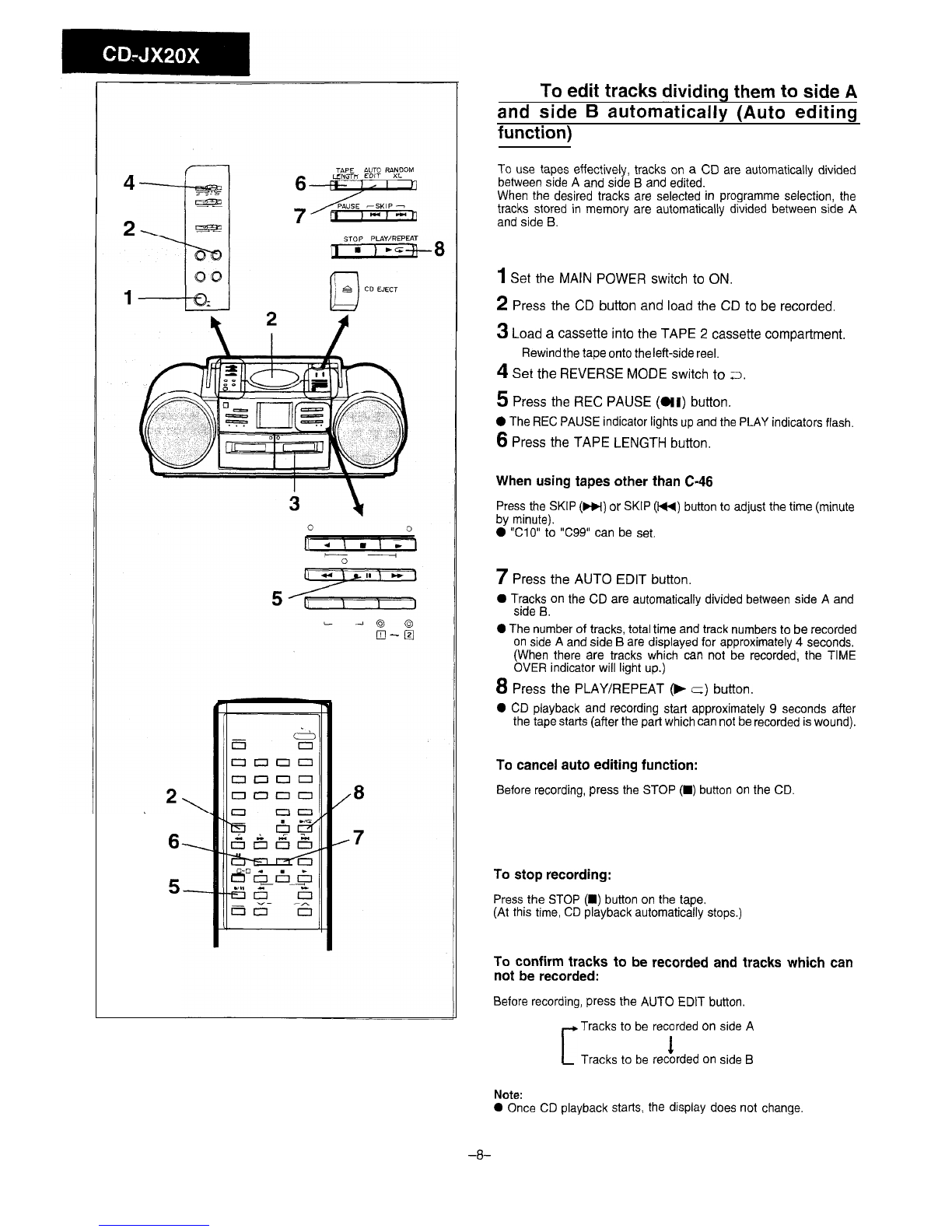
Before setting the
timer
clock, make sure
that
the current time
bs
correct.
n
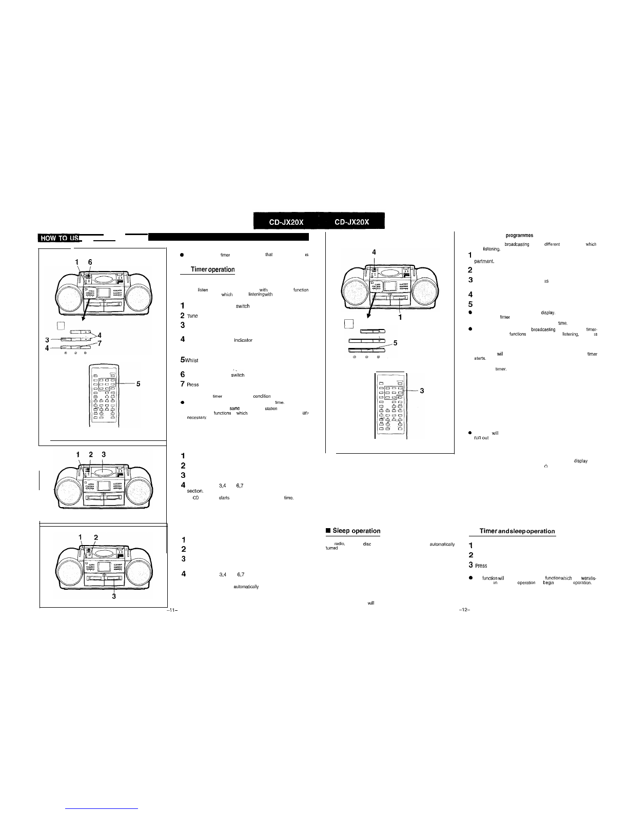
Timer
operation
To listen to the radio
You can
listen
to a broadcasting station wth the timer-on
function
different from that to
which
you are
lkstening
wth timer-off function.
However, the band should be the same
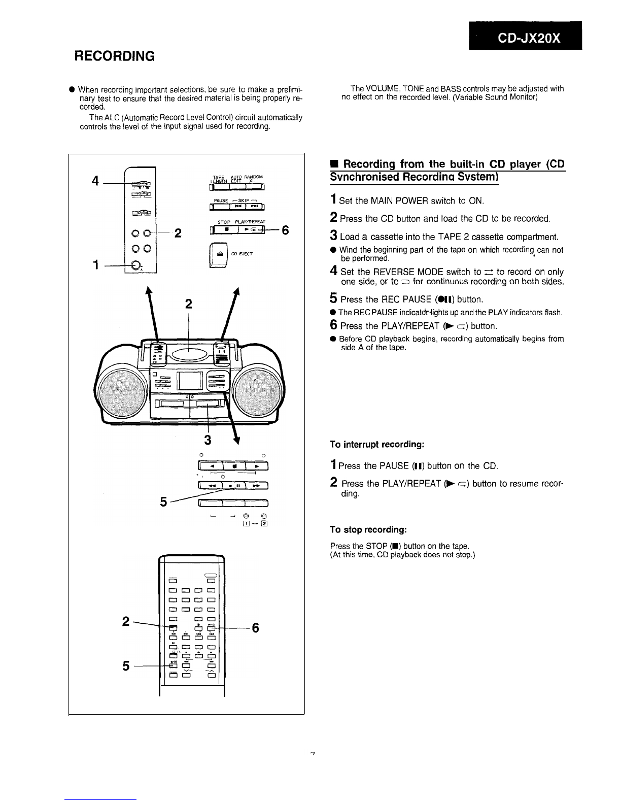
1Set the MAIN POWER switch to ON
2T
une into the desired station.
3
Press the DISPLAY button.
. The “ON TIME” Indicator goes on for 5 seconds.
4
Whilst the “ON TIME” mdicator is lit, and whilst pressing
the TIME ADJ button, press the HOUR and MINUTE but-
tons to set the desired time.
5
Whilst the “ON TIME” indicator is lit, select the desired
preset station on the remote control.
6
Set the TIMER REC
s&oh
to OFF.
7P
ress the TIMER button.
. The “TIMER SET” appears on the display.
This sets the
tmw
to the stand-by
conditlan
b
The radio turns on automatically at the preset
time.
.
When you listen to the
?.ame
broadcasting
slatron
with the timer-on
and timer-off
functions
to
which
you are listening, step 5 is
un-
To listen to the compact disc
1
Set the MAIN POWER switch to ON
2
Press the CD button
3
Load the disc.
4
Perform steps 3,4 and 6,7 of the “To listen to the radio”
sectloll.
. The
CD
playback statis automatically at the preset
time.
To playback a cassette
1Set the MAIN POWER switch to ON.
2
Press the TAPE button.
3
Load the recorded cassette tape into the TAPE 2 cassette
compartment,
4
Perform steps 3,4 and 6,7 of the “To listen to the radio”
section.
. Cassette playback starts
automatlcally
at the preset time.
t
i
n
W
Sleep
operation
The
radio,
compact
disc
and cassette deck can all be
automatically
turned
off after 60 minutes.
Press the SLEEP button.
To stop the sleep operation:
Press the SLEEP button.
(The SLEEP indicator wll go out.)
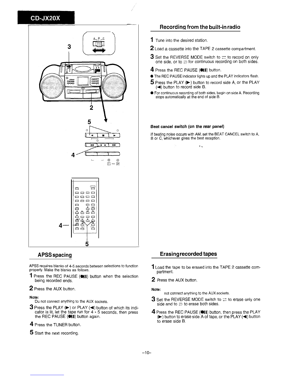
To record radio
programmes
You can record a
broadcasting
station
different
from that to
which
you are
listening.
However, the band should be the same.
1
Load a blank cassette tape into the TAPE 2 cassette corn-
partment.
2
Perform steps 1-4 of the “To listen to the radio” section.
3
Whilst the “ON TIME” Indicator
IS
lit, select the desired
preset station on the remote control.
4
Set the TIMER REC switch to ON.
5
Press the TIMER button.
0
The “TIMER SET” appears on the
display.
This sets the
timer
to the stand-by condition.
l
Recording starts automatically at the preset
tme.
b
When you record to the same
broadcastmg
station with the
timer-
on and timer-off
functions
to which you are
Ilstening.
step 3
is
unnecessary.
Notes:
l
The power wll be automatically turned off 2 hours after the
timer
starts.
l
To set the dewed volume level, use the VOLUME control before
setting the
timer.
To confirm the timer time setting:
Press the DISPLAY button
0
The tuner
will
keep accurate time until the clock/memory batteries
run
O”,
To cancel timer operation:
Press the TIMER button so that the “TIMER SET” in the
display
goes
out, or set the MAIN POWER switch to
(‘1
STAND-BY.
n
Timer
and
sleep
operation
1
Use the left procedure to confirm the sleep time
2
Set the timer time.
3P
ress the TIMER button. The “TIMER SET” appears on
the display.
b
The
function
wrll
not change, so the
function
which
you
were
IIS-
tening to
I”
the sleep
operatton
will
bqn
the timer
operabon.
Il-
-12-


/(W) User manual")


 User manual")