Sharp Wizard OZ-770PC User manual

MODEL OZ-770PC
ZQ-770PC
DISPLAY SECTION
ELEMENT: FSTN LCD
DISPLAY: 239 x 80 dot matrix
liquid crystal display
LSI
CPU: T5L55
POWER SUPPLY
AC: ✕DC:
Main power supply: 3 VDC Alkaline batteries (LR6 (size"AA") x 2)
POWER CONSUMPTION
0.33 W
DIMENSIONS
Open: 162 (W) ×145 (D) ×10.9 (H) mm.
Closed: 162 (W) ×81.5 (D) ×19.9 (H) mm.
Weight
OZ-770/ZQ-770: 220g (including batteries)
Operating temperatures
0°C to 40°C (32° to 104°F)
Peripherals and data transfer interface
Cable jack 4-pin connector
Electronic Organizer unit section
Applications Calendar, Schedule, To Do, Birthday/Anniversary,
Telephone, Memo, Expense, Expense Report,
Clock, Calculation, Conversion, Add-on
Memory
capacity OZ-770
ZQ-770: 2.5MB Flash memory
User area approx. 1,920KB for data
storage, 320KB for Add-on programs.
Application
capacity OZ-770
ZQ-770: 20,000 entries
(Schedule 5,000, Tel 5,000, Memo 5,000,
To Do 3,000, Expense 2,000) in total
These capacities assume the following average
entry sizes.
Schedule: 22 characters/entry
Tel: 8 characters/entry in the name field
10 characters/entry in number field
Memo: 12 characters/entry in title field
18 characters/entry in body field
To Do: 30 characters/entry in description field
Expense: 6 characters/entry in Amount field
4 characters/entry in Payment Type field
11 characters/entry in Memo field
Maximum storage in each application: 5,000 entries
Maximum data
size per entry Approx. 2,000 bytes (including
separator/terminator)
User interfaces Keyboard
Other features Secret function, data, transfer, search function, et
al.
Functions Addition, subtraction, multiplication, division,
constant, memory calculation, conversion
calculation.
Clock
Crystal oscillation frequency: 32,768 Hz
Accuracy: Average variance per day, 2.0 seconds
(at 25°C/77°F)
Display information: year, month, day, day of the week, hours,
minutes, A.M./P.M., city names
Time system: 12-hour and 24-hour
Other function: Display of date and time for various cities around
the world. Enable/disable daylight saving time.
Battery life
Battery life Battery life may vary depending on usage.
Approx. 120 hours. Continuous display at an
ambient temperature of 25°C (77°F)
Approx. 100 hours. Searching data for 5 min-
utes and display on for 55 minutes per hour,
at an ambient temperature of 25°C (77°F)
Approx. 90 hours. Using the Backlight for 2
minutes per hourly use an searching for 5
minutes per hourly use at and ambient tem-
perature of 25°C (77°F)
Please be reminded that the old batteries in
the Organizer should be exchanged with new
one at least once a year.
Backlight life Backlight life may vary depending on usage.
If the backlight is on for 10 minutes per day (eg.
1 minute 10 times a day), the brightness will be
reduced by half after 10* years (at an ambient
temperature of 25°C and 65% humidity).
This figure may vary depending on the sur-
rounding environment.
Accessories
Alkaline batteries LR6 (size "AA") x 2, Operation manual, Quick Start
Guide, Docking module, Software CD-ROM
SHARP CORPORATION
Parts marked with " " are important for maintaining the
safety of the set. Be sure to replace these parts with specified
ones for maintaining the safety and performance of the set.
This document has been published to be used
for after sales service only.
The contents are subject to change without notice.
SERVICE MANUAL

1. KEY LAYOUT AND FUNCTIONS
Menu key
Opens the Application Menu
Arrow keys
4-pin cable jack
Connects 4-pin Communication
Cable for PC synchronization.
keyboard
For entry of characters,
numbers and commands
ESC key
Cancels an operation
Page scroll keys
Quick press/release move up or down
one record at a time. Allows moving up
or down one screen at a time if held
down for a length of time.
Power key
Turns on and off the unit
Display
Shows information, and is used for
navigating the various functions
Application keys
Starts appropriate
applications
Backlight key
Reset button
Initializes and resets
the Organizer.
Battery replacement switch
Locks the battery
compartment to prevent
access to the batteries.
Operating battery compartment
Holds operating batteries.
4-pin Cable Jack
Connects 4-pin Communication
Cable for PC synchronization.
>>>>> USE FONT <<<<<
Helvetica/ Helvetica-Condensed/ Century-Schoolbook/ Symbol & OriginalFonts: (RingWorld2/RingFont2/Pa
Symbol/PartsCod)
- - - - - - - - - - - - - - - - - - - - - - - - - - - - - - - - - - - - - - - - - - - - - - - - - - - - - - -

2. HARDWARE DESCRIPTION
1. Block diagram
2-1. CPU (T5L55) : COB (Bare Chip) is used
1) Features
•Microcontroller T5L55 is a revised version of T6B31
•Added/revised functions of T5L55 compare to T6B31 are follows.
1. IrDA1.0 encorder/decorder circuit is integrated.
2. 120 segment LCD driver controller function is aclded.
3. LCD refresh frequency is revised.
4. Some gate circuits such as the interrupt circuit, the reset circuit
and the latch circuit are added.
•The chip has 100 pads. The pad pitch is 150um, and is as same
as T6B31.
•Operating voltage : VDD = +4.5 ~ +5.5V
2-2. LCD driver (JT6J14-AS) : COB
(Bare Chip ) is used
The JT6J14-AS is an 120-channel-output column driver for an STN
dot matrix LCD. The JT6J14-AS features 28-V LCD drive voltage and
a 10-MHz maximum operating frequency. The JT6J14-AS is able to
drive LCD panels with a duty ratio of up to 1/160.
1) Features
•Display duty application: to 1/160
•LCD drive signal: 120
•Data transfer: 4-bit bidirectional
•Maximum Operating frequency: 10 MHz (VDD = 4.5 V),
6.5 MHz (VDD = 2.7 V)
•LCD drive voltage: 11 to 28 V
(maximum drive voltage = 30 V)
•Power supply Operating voltage:2.7 to 5.5 V
•Operating temperature: –20 to 75°C
•LCD drive output resistance: 2.2 kΩ(max)
(12.8 V, 1/7 to 1/14 bias)
•Display-off function: When /DSPOF is L, all LCD drive out-
puts (O1 to O120) remain at the VSS/V5
level.
•Low power consumption: Cascade connections and auto enable
transfer functions are available.
Key Board
Matrix
Battery Replacement
Switch
Reset Switch
Power ON Button
Main Battery Voltage
Detection
CPU JT5L55
CPU core
Z80
Level Converter
4P Serial Communications
Port
(for PC synchronize)
9.8304MHz
X'tal
32.768kHz
X'tal
Main Clock
RTC
Clock
Oscillator
Main Clock
Oscillator
IrDA
Encoder
/Decoder
Serial
Interface
Interrupt
Controller Chip Select
Controller
LCD
Controller
FROM
16Mbit
FROM
8Mbit
SRAM
1Mbit
Vcc
Vbatt
Voltage
Detector
Power Conversion
(5.0V Step Up)
Main Batteries
(LR6 x 2)
Piezo Electric
Buzzer
Step Up
Segment Driver
120 segment Segment Driver
120 segment
LCD
239seg x 80com
Contrast
Adjust
LVC
Common
Driver
80 common
EL Driver
EL Backlight

2-3. LCD Driver (JT6J15-AS) : COB (Bare Chip) is
used
The JT6J15-AS is an 80-channel-output row driver for an STN dot
matrix LCD. The JT6J15-AS features 28V-LCD drive voltage. The
JT6J15-AS is able to drive LCD panels with a duty ratio of up to
1/160.
1) Features
•Display duty application: to 1/160
•LCD drive signal: 80
•Data transfer: Two different styles of 1-bit bi-direc-
tional can be selected
COM 80 COM 1
COM 80 COM 1
•LCD drive voltage: 11 to 28 V (maximum drive voltage
= 30 V)
•Operating voltage: 2.7 to 5.5 V
•Operating temperature: –20 to 75°C
•LCD drive output resistance: 1.5 kΩ(max)
(Vo = 12.8 V, 1/7 to 1/14 bias)
•Display-off function: When /DSPOF is L, all LCD drive
outputs (O1 to O80) remain at the
VSS/V5 level.
•LCD drive output timing: Change on falling edge or rising
edge of LP (selected by TSW)
2-4. DC-DC conector (XC 6372A)
1) Pin Assignment
2) Pin Description
XC6372A
PIN NUMBER PIN NAME FUNCTION
XC6372A
1V
SS GND
2V
OUT Output voltage monitor /
IC internal power supply
3L
XSwitch
— EXT External switch transistor drive
3) Block Diagram
XC6372A
VDD is internally connected to the VOUT pin.
2-5. Static RAM
1) OUTLINE
The TC551001CP is a 131,072-word x 8-bit, 5-V driven asynchronous
high-speed CMOS static RAM. The power consumption is 5mA/MHz
(standard) in operation and the access time is a maximum of 5ns;
that is, the use of a new circuit has turned high speed and low power
consumption into reality. In addition, the power consumption is only
1µA in standby state and data can be backed up by the battery.
2) Features
•Low power consumption: 27.5 mW/MHz (standard) in operation
•5-V power supply: 5V 10%
•Data retaining power supply voltage: 2V ~ 5.5V
•Output buffer control: OE
•I/O complete TTL compatible
•Standby current (max):
TC551001CP/CF/CFT/CTR/CST/CSR
–55, –70, –85 –55L, –70L, –85L
5.5V 100 µA 20 µA
3.0V 50 µA 10 µA
•Access time (max)
TC551001CP/CF/CFT/CTR/CST/CSR
–55, –55L –70, –70L –85, –85L
Access time 55ns 70ns 85ns
CE1 access time 55ns 70ns 85ns
CE2 access time 55ns 70ns 85ns
OE access time 30ns 35ns 45ns
•Package
TSOP I 32-P-0820-0.50 (CFT) (Mass:0.34 standard)
3) Pin configurations
•32 pin TSOP
(Normal bend type)
4) Pin names
A0 ~ A16 Address input
R/W Read/write input
OE Output enable input
CE1, CE2 Chip enable input
I/O1 ~ I/O8 Data I/O
VDD Power supply terminal (+5V)
GND Ground
N.C. Not used
321
SOT-89-3
(TOP VIEW)
Lx
VSS
EXT
CE
Vout
Buffer
Slow Start
Vref
PWM como
PWM Controlled
OSC
50/100/180khZ
VDD
Chip Enable
VLx Limiter
116
3217
(TOP VIEW)
(Normal bend type)

Pin No. 1 2 3 4 5 6 7 8 9 10 11 12 13 14 15 16
Pin name A11 A9A8A13 R/W CE2 A15 VDD N.C. A16 A14 A12 A7A6A5A4
PinNo. 17181920212223242526272829303132
Pin name A3A2A1A0I/O1 I/O2 I/O3 GND I/O4 I/O5 I/O6 I/O7 I/O8 CE1 A10 OE
2-6. Voltage Detector
1) General description
The XC61A Series is a voltage detector with high precision and low
current consumption that has been achieved by using CMOS process
and laser triming technology. It consists of high-precision and low
current consumption reference voltage source, a comparator, hyster-
isis circuit, and an output driver circuit. The detection voltage attains
high precision and minimun temperature drift. Two types of output
circuits, N-ch open drain and CMOS, are available. All these functions
in a mini-mold package attains space saving and high-density mount-
ing, thus making it best suited to hand held or compact equipment.
2) Block diagram
(1) CMOS output
(2) Nch open drain output
3) Pin configurations
4) Pin function
PIN FUNCTION
VIN INPUT TERMINAL
VSS GND TERMINAL
VOUT OUTPUT TERMINAL
3. Memory mapping
CHIP
SELECT DESCRIPTION SIZE
/CE1 FLASH ROM (PROGRAM DATA) 16Mbit
/CE3 — —
/CE4 — —
/CE5d,
/CE RAMd SRAM 1Mbit
/CE7 — —
/CE8 — —
4. Power circuit
•Explanation of the power source name
Normal
VCC5.0V System LSI power 5.0V
VBAT.Battery voltage 3.0V
GND reference voltage 0V
•Supply of the operating power (LR6 alkaline battery x 2)
The operating voltage (main battery) of 3V (1.5V x 2) is boosted to
5.0V by a DC/DC convertor to supply the 5.0V system power
(VCC).
•The 3V system power (VBAT: Battery voltage) is supplied from
main batteries directly.
5. Low battery detection
The main battery voltage is detected in two levels. When the voltage
falls to the caution level, "BATT" symbol lights up. When the voltage
falls to the fatal level, the power is forcibly turned off.
Max. Typ. Min.
Main Batt. Caution 2.10V 2.25V 2.40V
Fatal 1.70V 1.85V 2.00V
6. Current consumption check
Measurement conditions
•Power voltage: Main battery
3.0V (Battery terminal)
•Checker: Do not install a checker which consumes
power. (Example: 4pin checker)
Specification
•Current consumption during display of the diag menu : 12mA
•Current consumption during OFF :OZ/ZQ-770 120µA
Vref
VSS
VIN
VOUT
Vref
VSS
VIN
VOUT
SOT-89
(TOP VIEW)
1
VOUT VSSVIN
2
3

3. NOTE FOR SERVICING
1. Resetting the Organizer
A strong impact, exposure to an electrical field, or other unusual
conditions may render the unit inoperative, and pressing the keys will
have no effect. If this occurs, you will have to press the RESET switch
at the bottom of the unit using a pen or similar object to be able to
continue to use the unit.
A condition that makes the unit inoperative may erase some or all
of the data stored in memory.
Do not use anything breakable, anything with a sharp tip or any-
thing that might break to press the RESET switch.
In case that the Organizer does not work properly after reset, you can
remove the batteries and insert the batteries several seconds later.
Then press [ O
|] to open the Organizer.
1-1. All reset opeation
If the unit still fails to function after it has been reset using the proce-
dure above, you will have to reset it using a slightly more complicated
procedure:
1. While pressing and holding [ O
|], press and release the RESET
switch.
A message appears.
2. Release [ O
|].
3. Press [ ESC ].
The built-in clock is reset.
Do not press [ ENTER ] in step 3. Doing so will delete all data in
the unit.
2. Battery Replacement
2-1. General guidelines
The Organizer uses the following type of battery:
Use Type Size/Model Qty
General operation Alkaline batteries LR6 (size "AA") 2
There are some extremely important points to remember
when installing new batteries:
Replace the two operating batteries at the same time with new batter-
ies of the same type.
Caution:
Keep batteries out of the reach of children.
Remove batteries from the unit when they become weak or when
the unit will not be used for a long period of time.Leaving weak
batteries in the unit may cause battery leakage and damage from
corrosion.
Do not dispose of batteries in fire as they may explode.
2-2. Replacing the operating batteries
The Organizer detects two low battery levels which are warning and
fail. When the battery is in warning level, an alert message appears
on the screen. In fatal level, the Organizer will turn off automatically
without indication.
If the alert message is shown, replace the batteries immediately.
1. Turn off the Organizer.
2. Set the battery replacement switch on the bottom of the Organizer
to REPLACE BATTERIES (a red dot will appear).
3. Slide off the operating batteries cover.
4. Remove the old batteries by pulling the ribbon tab.
5. Insert the two new batteries on top of the ribbon tab, taking care to
position them correctly according to the plus ( + ) and minus ( - )
terminals, as shown below.
6. Replace the cover.
7. Set the battery replacement switch to NORMAL OPERATION.
8. Turn on the Organizer and set the clock.
If nothing happens when you press [ O
|] :
Setting the battery replacement switch to REPLACE BATTERIES
shuts off power to the unit. Check that the battery replacement
switch is set to NORMAL OPERATION.
Repeat the above battery replacement procedure step by step.

3. Using the data transfer function
Your Organizer is a powerful pocketsize computer with built-in functions
that make it possible to accomplish a broad range of tasks. It has the
flexibility to connect to other Organizers and transfer data to desktop
computers using data transfer facilities, which are accessed through the
application menu. This chapter provides descriptions and examples to
get you up and running quickly with these powerful features.
Exchanging Information with a Personal Computer
Using included Organizer Link software (Day-Timer Organizer
SHARP Edition) and cable (Docking Module), you can exchange data
with a personal computer. This makes it possible, for example, to use
the unit when outside your home or office, then later transfer the data
you have entered on the Organizer to your desktop computer.
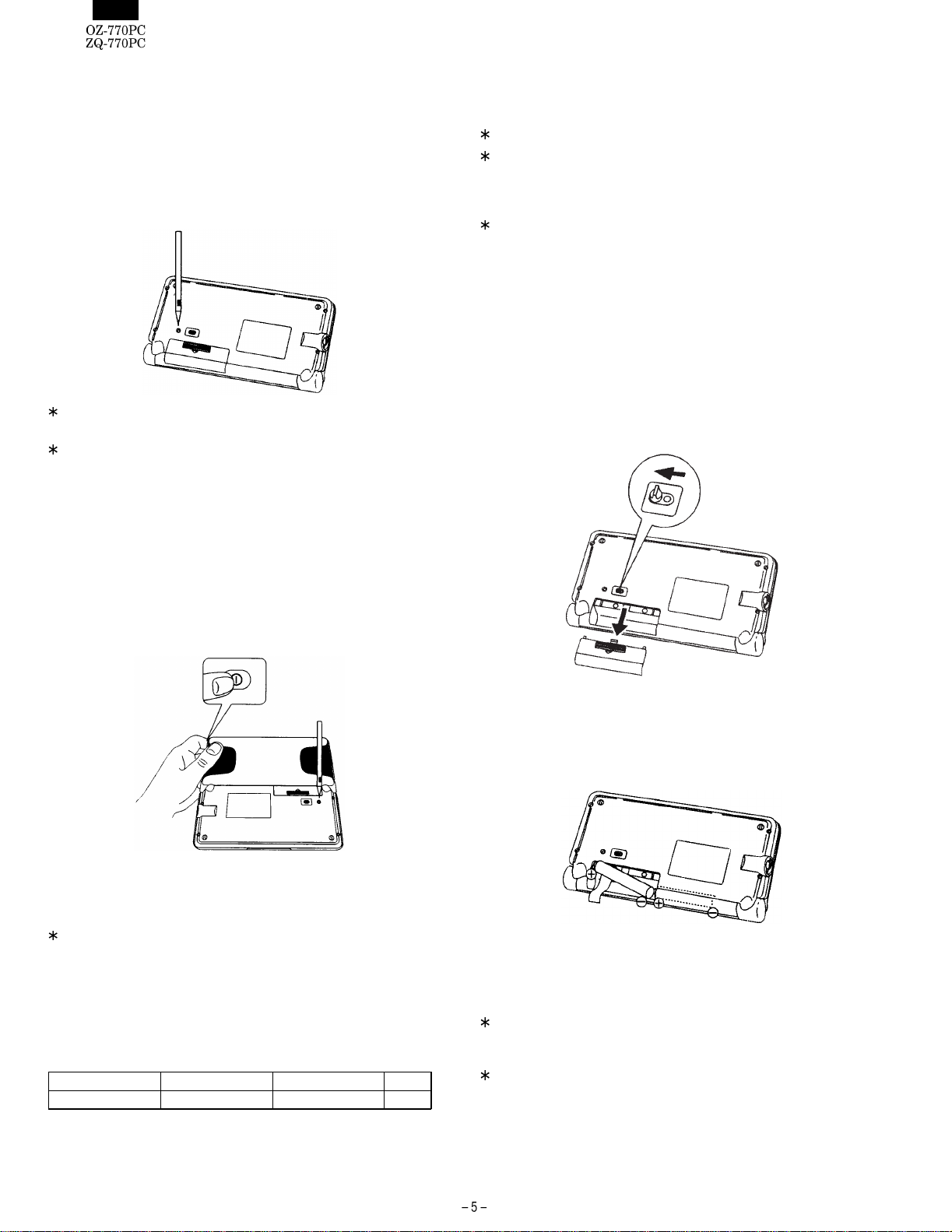
To setup the Organizer for use with the Organizer Link:
1. Make sure the unit is turned off.
2. For PC Interface cable transfer, plug the Organizer into the Dock-
ing Module. (See the "Quick Start Guide" for details.)
3. Plug the cable into the jack on the OZ/ZQ-770 and into the PC’s
serial port (e.g. COM1)
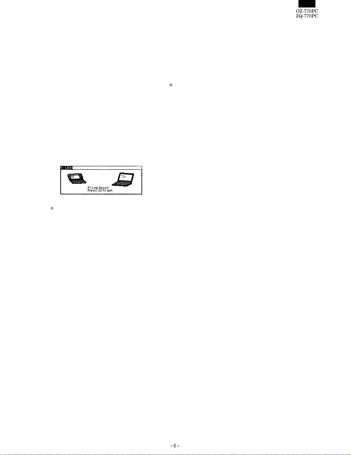
4. Turn on OZ/ZQ-770, press [ 2nd ] [ MENU ] to activate the PC-LINK.
Your Organizer is now ready to transfer data. Consult the Day-timer
Organizer SHARP Edition HELP file regarding subsequent transfer pro-
cedures.
Press [ O
|] at any time to exit the PC-Link mode. If you leave the
Organizer in PC Link mode, more power is consumed from the batter-
ies than usual, and the auto power off function does not work.
To conserve battery power, always press [ O
|] to leave the PC Link
mode as soon as you have finished transferring data.
4. Concerning the internal user
FLASH-ROM data.
In the OZ/ZQ-700 series, all of the registered user’s data is stored in
the FLASH-ROM memory, and is therefore stored even if there is no
power supplied to the machine.
However, the FLASH-ROM memory is cleared during the following
operations, and caution should be exercised concerning data storage
management.
(Operations which will erase the user data storage
memory)
1) When the ALL RESET function is carried out.
2) When the following functions are carried out from the Diag Check.
(1) "5. FINAL check" (page 1/5)
(2) "5. AGING" (page 2/5)
(3) "1. FLASH ROM CLEAR" (page 5/5)
5. FLASH ROM SERVICE
WRITING/CHECKING PROCEDURES
The procedures are for writing into the FLASH ROM is the OZ/ZQ-
700 series.
Servicing for the OZ/ZQ-700 series is performed in the following cases:
1) When the Main PWB unit is replaced.
2) When the FLASH ROM is replaced.
3) When the following functions are carried out from the Diag Check.
(1) "5. FINAL check" (page 1/5)
(2) "5. AGING" (page 2/5)
(3) "1. FLASH ROM CLEAR" (page 5/5)
1) Necessary devices
1. PC (Windows 95/98 or Windows NT 4.0)
2. Docking module
3. RE-PROGRAM software for PC (EO8RPRxxxx.exe)
"xxx" shows the version number. The software on the machine
side is included in this software.
When the version of the software on the machine side is up-
graded, this software is also upgraded.
2) Operating procedure
1. Connect the machine and the PC’s COM port with the docking module.
2. Copy the RE-PROGRAM software (EO8RPRxxxx.exe) for PC into
a directory in the HDD.
3. Start the program copied in procedure 3.
4. If necessary, set the COM port for PC software. (It is normally
operated when detected.)
5. Select [ON]-[2nd]-[MAIN] to bring the machine into the PC-Link mode.
6. Press the Update button of the program to start RE-PROGRAM.
PC side: The window indicating the progress status is shown.
Machine side: A beep sounds and the machine enters the PC-
Link mode to be ready for reception. The display
shows; Now updating!
Please waitc
7. Re-program is completed in about 6 min.
PC side: "The system update was successful." is displayed.
Machine side: A beep keeps sounding periodically. The display
shows; Re Program
Ok
8. Press the OK button on the PC message to complete the program.
9. While pressing [ESC] and [D] on the machine side, press the
Reset button and release [ESC] and [D] to enter the diag. mode.
Check the machine model name, the ROM version, and the check
sum. The checking procedures are as follows:
1) Model name, ROM version
Check the right lower section of the first page (Page 1 of 5) of
the diag. menu.
Ex. Model: EO-8
Page 1 of 5
ROM Ver. V1.1
2) Check sum
Press [V] key once in the first page (Page 1 of 5) of the diag.
menu to go to the second page of the diag. menu (page 2 of
5). Press [2] and select "ROM CHECK." After completion, a
beep sounds.
If the check sum is OK, the check sum and "ROM CHECK OK"
are displayed on the display after completion. After that, check
the check sum value. In case of an error, two different check
sum values and "ROM CHECK FAIL" are displayed.
Perform the check procedure again.
10.After completion of the above, keep pressing [POWER] key and
press the reset key. The display of initializing execution check is
shown. Press [ENTER] key to initialize the machine.
[Note]
•If the check is failed, perform the following procedure instead of
procedure 5.
While pressing [SHIFT] + [R], press [RESET] to bring the machine
into the PROGRAM mode and perform procedures 3 and later again.
•If necessary, back up the data before RE-PROGRAM, and restore
them after completion of RE=PROGRAM.

4. EXPLANATION OF DIAGNOSTICS AND CHECK ITEMS
NO. CHECK ITEM CHECK METHOD DISPLAY CRITERIA or NOTE
1 Start Power SW ON
Reset while Pressing ESC+D (Diag Menu, Page 1 of 5)
1. LCD CHECK
2. PCB CHECK
3. KEY CHECK
4. BACKLIGHT CHECK
5. FINAL CHECK
6. LOW BATT. CHECK
7. H SEND CHECK
8. UART ECHO CHECK
ROM Ver. Vx,x
2 LCD Check Push 1 key Displayed Frame Pattern
Push ENTER key Displayed Checked Pattern 1
Push ENTER key Displayed Checked Pattern 2
Push ENTER key Displayed Rain Drop Pattern 2
No Rain Drop
Push ENTER key Contrast changes smoothly to black out,
fades out, then returns to the initial level.
3 PCB Check Push ‘2’ key
Push ENTER
SRAM CHECK.....
ROM CHECK.....
ALARM TONE TEST.....
Test OK should be seen, or a error alarm
tone would be heard.,
4 KEY Check Push ‘3’ key
Push all key 45 (hex) different characters and the no.
of keys are displayed. When push a key, one of corresponding
characters will be disappeared and the no.
of key will be decrement by one.
Keyboard will be OK only if all characters
had been disappeared after all keys had
been pressed.
5 Backlight check Push ‘4’ key BackLight is on & no indication on time...30sec
6 Low Battery Check Push ‘6’ key
Drop the operating Volt. 2.5V
Drop the operating Volt. 2.1V
Drop the operating Volt. 1.7V
LOW BATTERY CHECK
LOW BATTERY CHECK (no change)
CAUTION!
IT IS LOW BATTERY.
FATAL WARNING.
IT IS NO BATTERY
7 H Send Check Connect the OZ/ZQ-700
series unit to PC Push ‘7’ HHHHH.......
HHHHH.......
:
:
Press CANCEL to exit
Check ‘H’ displaying to PC Monitor
8 Uart Echo Check Connect the OZ/ZQ-700
series unit to PC & run rest
Cradle PC program.
UART CHECKING.......
Press CANCEL to quit Test OK should be seen.
(Frame Pattern)
(Checked Pattern 1)
(Checked Pattern 2)
(Rain Drop)
(Contrast Check)
Dark
Light
Time

TO SHEET 4
FPCB
TO SHEET 5
FROM SHEET 4
The SW. open
when the door is locked.
TO SHEET 4
TO SHEET 3
FROM SHEET 4
TO SHEET 5
2.2uF
5. CIRCUIT DIAGRAM AND PARTS LAYOUT
(1) Main PWB Circuit
1CPU

2Memory
FROM SHEET 2
FROM SHEET 2
FROM SHEET 4
FROM SHEET 2
(TSOP)
(TSOP)
LHF08CH1
U12 is not mounted
Trace only

34pin
EM3 MMZ2012D301B
MMZ2012S102A
MMZ2012S102A

4Key

5 Power

(2) Main PWB parts layout

(3) Main PWB pattern layout

(4) LCD PWB Circuit
1 LCD driver

2 EL power

3Key

(5) LCD PWB parts layout

(6) LCD PWB pattern layout
This manual suits for next models
1
Table of contents
Other Sharp Organizer manuals

Sharp
Sharp OZ730 Operation User manual

Sharp
Sharp ZQ-290 User manual

Sharp
Sharp YO-P20HII User manual

Sharp
Sharp EL-6850 User manual

Sharp
Sharp YOP20HII - 1MB Electronic Organizer User manual

Sharp
Sharp YO-300 User manual

Sharp
Sharp EL-6071 User manual

Sharp
Sharp EL-6985 User manual

Sharp
Sharp EL-6900 User manual

Sharp
Sharp ZQ-4300 User manual