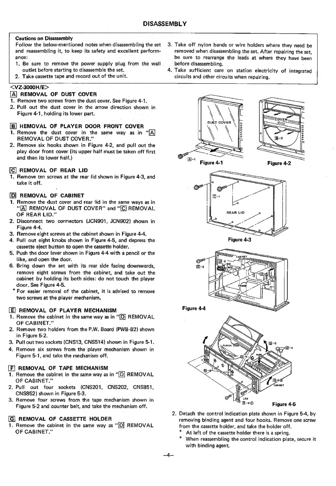
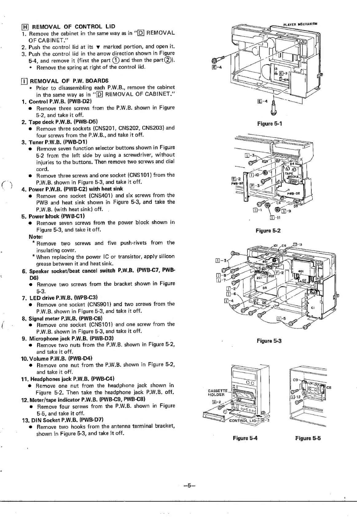
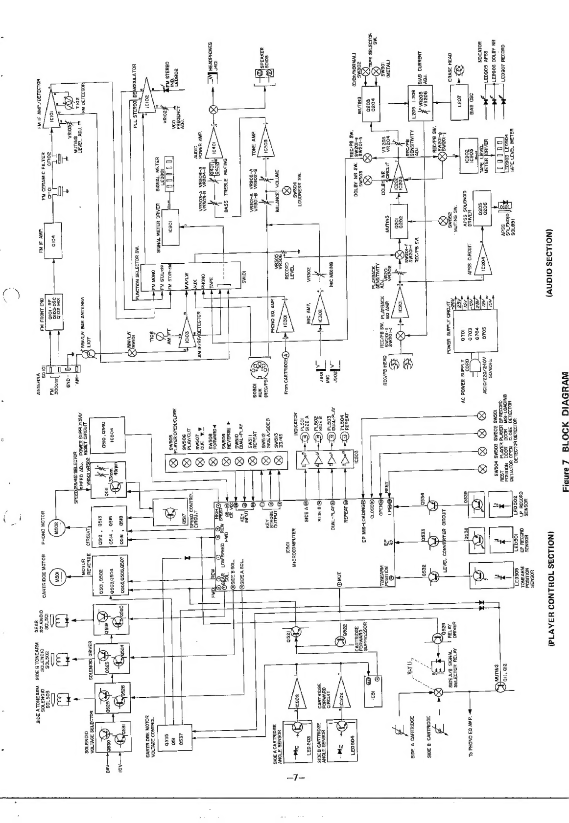
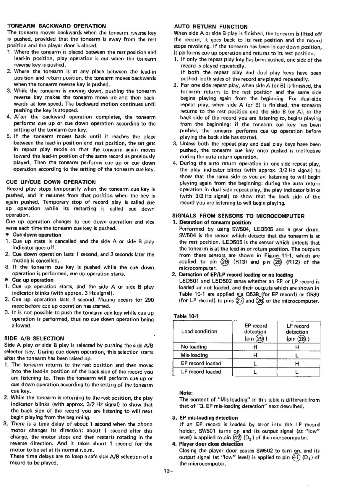
Sharp VZ-3000H User manual

SHARP
SERVICE
MANUAL
ATSM68
107
1MCT
VZ-3000H/E_
CP-V300H
VZ-3000H/E
CP-V300H
In
the
interests
of
user-safety
the
set
should
be
restored
to
its
original
condition
and
only
parts
identical
to
those
specified
be
used,
(The
record
in
the
photo
is
not
an
accessory.)
Main
Unit:
VZ-3000H
Speaker
Box:
CP-V300H
OO
®
@
APSs
Noise
reduction
system
manufactured
under
license
from
Dolby
Laboratories
Licensing
Corporation.
“Dolby”
and
the
double-D
symbol
are
trademarks
eee
of
Dolby
Laboratories
Licensing
Corporation.
:
Auto
Program
Search
System
Photo
\
INDEX
TO
CONTENTS
FEATURES»
s.ss.g0hasbisascccawid
sat eee
te
Sree
danas
aa
eee
Top.
ADJUSTMENT
OF
TUNER
CIRCUIT
..........
18
~20
SPECIFICATIONS
........2c
cscs
eeenee
eset
eneonn
2
CP-V300H
(SCHEMATIC
DIAGRAM/WIRING
VOLTAGE
SELECTION
.......ccccececn
cece
ee
eees
2
CONNECTION/EXPLODED
VIEW)...............
20
NAMES
OF
PARTS
.....
cc
cece
ceee
cree
e
rene
enone
3
SCHEMATIC
DIAGRAM
(1/4
~
4/4)
..........
21
~28
DISASSEMBLY
........
ccc
eee
ee
eee
eee
eee
4~6
WIRING
SIDE
OF
P.W.
BOARD
(1/3
~
3/3)
....
29
~34
DIAL
CORD
STRINGING
..........00e
eee
e
ee
eens
6
EXPLODED
VIEW
(PLAYER/CABINET/
SETTING
OF
PLAYER
WIRE
......-...00es
cere
eens
6
TAPE
DECK)
....--.seeeeseene
near
esnee
35
~39
BLOCK
DIAGRAM
.....
ce
cece
cece
ene
recente
ees
7
EQUIVALENT
CIRCUIT
CIRCUIT
DESCRIPTIONS
.........00--0e0e
eee
8~14
{BLOCK
DIAGRAM)
OF
IC
...............
40
~
42
ADJUSTMENT
OF
TAPE
DECK
MECHANISM
....
14,
15
TYPES
OF
TRANSISTOR
AND
LED
...........-...
42
ADJUSTMENT
OF
PLAYER
MECHANISM
.....
15~17
GAUTION
2204)
ses
ckiedieed
aching
ets
cna
coca
nine
ae
%
43
ADJUSTMENT
AND
CHECK
OF
RECORD/
AC
POWER
SUPPLY
CORD
WIRING
CONNECTIONS
,.
43
PLAYBACK
AMPLIFIER
CIRCUIT
...........--.
17
-
REPLACEMENT
PARTS
LIST
...............
44
~Back
PACKING
METHOD............ccee
eee
cece
eens
Back
FEATURES
<VZ-3000H/E>
<CP-V300H>
®
Automatic
playing
of
both
sides
of
a
record.
@
Atthe
speaker
section:
e
Fully
automatic
control
of
the
record
with
microcomputer
Bass
ref.
type
2-way
speaker
system
and
linear
tracking
mechanism.
16
cm
free
edge
woofer
®
Compact,
space-saving
vertical
player.
LC
type
network
SHARP
CORPORATION
OSAKA,
JAPAN

@
For
a
complete
description
of
the
operation
of
unit,
please
refer
to
the
operation
manual.
<VZ-3000H/E>
General
Rated
voltage:
Power
consumption:
Dimensions
(Main
unit):
Weight
(Main
unit):
Input
sockets:
Quiput
sockets:
Outer
sockets:
Semiconductors:
Amplifier
Section
Circuit:
Power
output:
Total
harmonics
distortion:
Frequency
response:
Tone
controls:
Tuner
Section
Circuit:
Frequency
range:
Intermediate
frequency:
Sensitivity:
Separation:
S/N:
<CP-V300H>
Speaker
Section
Cabinet
type:
Speakers:
Frequency
range:
Crossover
frequency:
SPECIFICATIONS
AC
110
V,
220
V,
240
V,
50/60
Hz
230
W
597(W)
x
170(D)
x
378(H)
mm
14.6
kg
Microphone:
1
mV/10K
ohms,
$6.3
mm
jack
Aux
(P.B.):
190
mV,
47K
ohms
Aux
(REC):
130
mV,
100K
ohms
Speaker:
4
ohms
Headphones:
8
ohms,
46.3
mm
jack
FM
antenna:
FM
300
ohms
balanced
MW/LW
antenna:
outside
antenna
Ground:
MW/LW
antenna
ground
1
LSI,
17
ICs,
1
FET,
54
transistors,
56
diodes,
7
LEDs,
2
photo-
transistors,
3
photo-interruptors
2
infrared
emitting
diodes
OCL
power
amp
with
+
power
supply
RMS;
25W
x
2
at
0.5%
THD,
4
ohms
0.1%
(4
ohms
at
20W
output)
40
Hz
~20
kHz
+1.5
dB
Bass:
+9
d8
(100
Hz)
Treble:
+9
dB
(10
kHz)
Superheterodyne
FM/MW/LW
tuner,
PLL
stereo
demodulaticn
circuit,
FM
muting
circuit
built-in
FM:
87.6
~108
MHz
MW:
520
~1,620
kHz
LW:
148.5
~285
kHz
[VZ-3000H]
150
~
285
kHz
[VZ-3000E]
FM:
10.7
MHz
MW/LW:
455
kHz
[VZ-3000H]
465
kHz
[VZ-3000E]
FM:
2.0uV
at
S/N
26
dB,
40
kHz
dev.
MW/LW:
350uV/m
FM:
36dB
(1
kHz
FM
stereo)
FM:
70dB
(monaural
1
kHz)
Bass
ref.
type
2-way
speaker
system
16
cm
free
edge
woofer
5
cm
tweeter
60
~
20,000
Hz
2,500
Hz
Woofer
high-cut;
6
dB/oct
Tweeter
low-cut;
12
dB/oct
VOLTAGE
SELECTOR
ADJUSTMENT
The
voltage
selector
is
located
on
the
rear
panel
of
the
deck.
If
adjustment
is
necessary,
use
a
screwdriver
in
order
to
turn
the
selector
in
either
direction
until
the
correct
voltage
figure
is
displayed
in
the
window
next
to
the
adjustment
screw.
Cassette
Deck
Section
Recording
tracks:
Recording
system:
Erasing
system:
Head:
Motor:
Tape
speed:
Fast
forward
time:
Rewind
time:
Wow
&
flutter:
Frequency
response:
S/N:
Player
Section
Type:
Motor:
Drive
system:
Speeds:
Wow
&
Flutter:
S/N:
Tonearm:
Cartridge:
Supplied
devices:
Maximum
rated
input:
Impedance:
Sound
pressure
level:
Dimensions:
Weight:
4
track
2
channel
stereo
system
AC
bias
(85
kHz)
AC
erasing
system
(85
kHz)
Record/playback
head
x
1,
Erase
head
x
1
Electronic
control
DC
motor
4.8
cm/sec.
100.sec.
(C-60
tape)
.
100.sec.
(C-60
tape)
0.2%
(DIN).
Normal
tape:
.30
~
14,000
Hz
Chrome
tape:
30
~
15,000
Hz
Metal
tape:
30
~16,000
Hz
Dolby
NR
off:
.
52
dB
Dolby
NRon:
62dB
{Metal
tape,
over
5
kHz)
Microcomputer
control,
Linear
tracking
full
auto,
Belt
drive
DC
motor
with
FG
(for
platter
drive)
x1,
DC
motor
(for
tonearm
drive)
x
1
Belt
drive
system
33-1/3,
45
rpm
0.085%
(DIN)
66
dB
(DiN-B)
Dynamic
balanced,
Linear
tracking
VM
type
Frequency
response:
20
~
20,000
Hz
Output
voltage:
2.8
mV
(1
kHz,
50mm/sec.)
Exchangeable
stylus:
STY-121
Automatic
door
open/close,
auto
lead-in,
auto
return,
auto
record
size
sensing,
automatic
speed
selec-
tion,
dual
play,
repeat
play
50
W
(MPQ)
4
ohms
89
dB/Wm
220{W)
x
220(D)
x
378(H)mm
4.7kgx1
*
Specifications
for
this
model
are
subject
to
change
without
prior
notice.

<VZ-3000H/E>
2
Front
Parts
23
Tape
Deck
Parts
24
35
Control
Parts
36
37
38
39
40
41
42
43
44
Rear
Parts
45
46
47
48
49
50
51
<CP-V300H>
Speaker
Parts
%
1
Tweeter
2
Woofer
NAMES
OF
PARTS
Power
Switch
Side
B
Play
Indicator
Dual
Play
{ndicator
Repeat-Play
Indicator
Side
A
Play
Indicator
Player
Door
Signal
Meter
FM
Stereo
Indicator
Function
Selector
Buttons
Volume
Control
Knob
Tuning
Control
Knob
Tape
Counter
Tape
Counter
Reset
Button
Player
Door
Open/Close
Key
Play/Cut
Key
Tonearm
Cue
Key
Tonearm
Forward
Key
Tonearm
Reverse
Key
Dual
Play
Key
Repeat-Play
Key
Side
A/B
Selector
Key
Headphones
Jack
Microphone
Jacks
APSS
Indicator
Dolby
NR
Indicator
29-3031
32
39°34
36
is
ab
a
6
QD
Record
Indicator
Figure
3-2
Tape
Deck
Parts
Figure
3-3
Contro!
Parts
Cassette
Holder
Tape
Level
Meter
Cassette
Eject
Button
Record
Button
Play
Button
Stop
Button
Rewind
Button
Fast
Forward
Button
Pause
Button
ig
oa
@
Speed
(33/45)
Selector
Key
Dolby
NR
Switch
Tape
Selector
Switches
Loudness
Switch
Record
Level
Control
Knobs
Bass
Control
Knob
Treble
Control
Knob
i
Balance
Contro!
Knob
i
ah
4
4
Mic
Mixing
Knob
Antenna
Sockets
AUX
(REC/P.B.)
input
Socket
Hole
to
open
player
door
in
case
of
power
failure.
Speaker
Socket
Beat
Cancel
Switch
AC
Power
Supply
Cord
Voltage
Selector
Figure
3-5
Speaker
Parts
pal
Yee

DISASSEMBLY
Cautions
on
Disassembly
ance:
outlet
before
starting
to
disassemble
the
set.
2.
Take
cassette
tape
and
record
out.of
the
unit.
<VZ-3000H/E>
REMOVAL
OF
DUST
COVER
1,
Remove
two
screws
from
the
dust
cover.
See
Figure
4-1.
2.
Pull
out
the
dust
cover
in
the
arrow
direction
shown
in
Figure
4-1,
holding
its
lower
part.
REMGVAL
OF
PLAYER
DOOR
FRONT
COVER
1.
Remove
the
dust
cover
in
the
same
way
as
in
“Al
REMOVAL
OF
DUST
COVER.”
2.
Remove
six
hocks
shown
in
Figure
4-2,
and
pull
out
the
play
door
front
cover
(its
upper
half
must
be
taken
off
first
and
then
its
lower
half.)
[C]
REMOVAL
OF
REAR
LID
1.
Remove
ten
screws
at
the
rear
lid
shown
in
Figure
4-3,
and
take
it
off.
[D]
REMOVAL
OF
CABINET
1.
Remove
the
dust
cover
and
rear
lid
in
the
same
ways
as
in
“TA]
REMOVAL
OF
DUST
COVER"
and
“{C]
REMOVAL
OF
REAR
LID.”
2.
Disconnect
two
connectors
(JCN901,
JCN902)
shown
in
Figure
4-4,
3.
Remove
eight
screws
at
the
cabinet
shown
in
Figure
4-4.
4.
Pull
out
eight
knobs
shown
in
Figure
4-5,
and
depress
the
cassette
eject
button
to
open
the
cassette
holder.
5.
Push
the
door
lever
shown
in
Figure
4-4
with
a
pencil
or
the
like,
and
open
the
door.
6.
Bring
down
the.
set
with
its
rear
side
facing
downwards,
remove
eight
screws
from
the
cabinet,
and
take
out
the
cabinet
by
holding
its
both
sides:
do
not
touch
the
player
door.
See
Figure
4-5.
*
For
easier
removal
of
the
cabinet,
it
is
advised.
to
remove
two
screws
at
the
player
mechanism.
[E]
REMOVAL
OF
PLAYER
MECHANISM
1.
Remove
the
cabinet
in
the
same
way
as
in
“[D]
REMOVAL
OF
CABINET.”
2.
Remove
two
holders
from
the
P.W.
Board
(PWB-B2)
shown
in
Figure
5-2.
3.
Pull
out
two
sockets
(CNS13,
CNS514)
shown
in
Figure
5-1.
4,
Remove
six
screws
from
the
player
mechanism
shown
in
Figure
5-1,
and
take
the
mechanism
off.
{F]
REMOVAL
OF
TAPE
MECHANISM
1.
Remove
the
cabinet
in
the
same
way
as
in
“(D]
REMOVAL
OF
CABINET.”
2.
Pull
out
four
sockets
(CNS201,
CNS852)
shown
in
Figure
5-3.
3.
Remove
four
screws
from
the
tape
mechanism
shown
in
Figure
5-2
and
counter
belt,
and
take
the
mechanism
off.
CNS202,
CNS851,
[G]
REMOVAL
OF
CASSETTE
HOLDER
1.
Remove
the
cabinet
in
the
same
way
as
“(DI
REMOVAL
OF
CABINET.”
Follow
the
below-mentioned
notes
when
disassembling
the
set
and
reassembling
it,
to
keep
its
safety
and
excellent
perform-
1.
Be
sure
to
remove
the
power
supply
plug
from
the
wall
3.
Take
off
nylon
bands
or
wire
holders
where
they
need
be
removed
when
disassembling
the
set.
After
repairing
the
set,
be
sure
to
rearrange
the
leads
at
where
they
have
been
before
disassembling.
4.
Take
sufficient
care
on
station
electricity.
of
integrated
circuits
and
other
circuits
when
repairing.
Figure
4-4
Figure
4-5
2.
Detach
the
control
indication
plate
shown
in
Figure
5-4,
by
removing
binding
agent
and
four
hooks.
Remove
one
screw
from
the
cassette
holder,
and
take
the
holder
off.
*
At
left
of
the
cassette
holder
there
is
a
spring.
*
When
reassembling
the
contro!
indication
plate,
secure
it
with
binding
agent.
a

a
[H]
REMOVAL
OF
CONTROL
LID
1.
Remove
the
cabinet
in
the
same
way
as
in
“(D]
REMOVAL
OF
CABINET.”
2.
Push
the
control
lid
at
its
w
marked
portion,
and
open
it.
3,
Push
the
control
lid
in
the
arrow
direction
shown
in
Figure
5-4,
and
remove
it
(first
the
part
(1)
and
then
the
part(2)).
*
Remove
the
spring
at
right
of
the
control
lid.
[i]
REMOVAL
OF
P.W.
BOARDS
*
Prior
to
disassembling
each
P.W.B.,
remove
the
cabinet
in
the
same
way
as
in
“[D]
REMOVAL
OF
CABINET.”
1.
Control
P.W.B.
(PWB-D2)
@
Remove
three
screws
from
the
P,W.B.
shown
in
Figure
5-2,
and
take
it
off.
2.
Tape
deck
P.W.B.
(PWB-D5)
@
Remove
three
sockets
(CNS201,
CNS202,
CNS203)
and
four
screws
from
the
P.W.B.,
and
take
it
off.
3.
Tuner
P.W.B.
(PWB-D1)
@
Remove
seven
function
selector
buttons
shown
in
Figure
5-2
from
the
left
side
by
using
a
screwdriver,
without
injuries
to
the
buttons.
Then
remove
two
screws
and
dial
cord.
®
Remove
three
screws
and
one
socket
(CNS101)
from
the
P.W.B.
shown
in
Figure
5-3,
and
take
it
off.
4.
Power
P.W.B.
(PWB-C2)
with
heat
sink
@
Remove
one
socket
(CNS401)
and
six
screws
fromthe
PWB
and
heat
sink
shown
in
Figure
5-3,
and
take
the
P.W.B.
(with
heat
sink)
off.
5.
Power
block
(PWB-C1)}
@
Remove
seven
screws
from
the
power
block
shown
in
Figure
5-3,
and
take
it
off.
Note:
*Remove
two
screws
and
five
push-rivets
from
the
insulating
cover,
*
When
replacing
the
power
IC
or
transistor,
apply
silicon
grease
between
it
and
heat
sink.
6.
Speaker
socket/beat
cancel
switch
P.W.B,
(PWB-C7,
PWB-
D6)
@
Remove
two
screws
from
the
bracket
shown
in
Figure
5-3,
7.
LED
drive
P.W.B.
(WPB-C3)
@
Remove
one
socket
(CNS901)
and
two
screws
from
the
P.W.B.
shown
in
Figure
5-3,
and
take
it
off.
8.
Signal
meter
P.W.B,
(PWB-C6)
@
Remove
one
socket
(CNS101)
and
one
screw
from
the
P.W.B.
shown
in
Figure
5-3,
and
take
it
off.
9.
Microphone
jack
P.W.B.
(PWB-D3)
@
Remove
two
nuts
from
the
P.W.B.
shown
in
Figure
5-2,
and
take
it
off.
10.
Volume
P.W.B.
(PWB-D4)
@
Remove
one
nut
from
the
P.W.B.
shown
in
Figure
5-2,
and
take
it
off.
11,
Headphones
jack
P.W.B.
(PWB-C4)
@
Remove
one
nut
from
the
headphone
jack
shown
in
Figure
5-2.
Then
take
the
headphone
jack
P.W.B.
off.
12.
Meter/tape
indicator
P.W.B.
(PWB-C9,
PWB-C8)
@
Remove
four
screws
from
the
P.W.B.
shown
in
Figure
5-5,
and
take
it
off.
13.
DIN
Socket
P.W.B.
(PWB-D7)
@
Remove
two
hooks
from
the
antenna
terminal
bracket,
shown
in
Figure
5-3,
and
take
it
off.
@)
pte
——_
CONTROL
LID
fA}
~Sey
Figure
5-4
5
3
PLAYER
MECHANISM
Figure
5-5

14.
Tape
mechanism
P.W.B.
(PWB-E)
®@
Remove
the
tape
mechanism
in
the
same
way
as
in
“(F]
Me
saet
er
Fe
pe
Ge
REMOVAL
OF
TAPE
MECHANISM.”
re
@
Remove
one
screw
from
the
record
selector
lever,
two
screws
from
the
motor
bracket
and
one
screw
from
the
P.W.B.
shown
in
Figure
6-1.
Then
take
the
P.W.B.
off.
15,
Microcomputer
P.W.B.
(PWB-B1)
@
Remove
the
player
mechanism
in
the
same
way
as
“(E]
REMOVAL
OF
PLAYER
MECHANISM.”
®
Remove
four
screws
from
the
P.W.B.
shown
in
Figure
6-2,
and
take
it
off.
Figure
6-2
<CP-V300H>
REMOVAL
OF
SPEAKER
BOX
1.
Speaker
net
@
As
shown
in
Figure
6-3,
pull
the
net
in
the
arrow
directions
in
the
numerical
order
(1),
(2),@)
and
().
The
parts
@
and
must
be
removed
by
using
a
bladed
screwdriver.
Figure
6-3
2.
Speaker
slated
@
For
removal
of
the
speaker,
see
Figure
20-4.
screwdriver
DIAL
CORD
STRINGING
cm.
@
Setting
order:
®
1.
Turn
the
drum
fully
counterclockwise
{at
the
highest
TY
hy
een!
|.
—
see
nn
frequency
position},
and
put
a
hook
of
the
spring
in
the
hole
of
the
drum.
2.
Proceed
with
stringing
in
the
numerical
order
from
1)
to
®.
Pointer
iaazt
3.
After
the
stringing,
turn
the
dial
drive
shaft
fully
counter-
ai
2
<
.
ae
.
.
uM
(472;
clockwise
(at
the
lowest
frequency
position),
and
align
the
=
:
center
of
the
pointer
to
zero
point
of
the
dial
scale
plate.
“O'Point
Cf
2Turns
4Turns
Figure
6-4
SETTING
OF
PLAYER
WIRE
®
Setting
order
Pe
eae
aera
1.
Set
the
drum
at
its
rest
position,
and
put
a
hook
of
the
spring
in
the
hole
of
the
drum.
2.
Stretch
the
wire
in
the
numerical
order
from
to
(2.
3.
After
setting
the
wire,
set
the
side
A
tonearm
and
side
B
tonearm
at
their
lead-in
positions.
Refer
to
the
instructions
in
“POSITIONAL
ADJUSTMENT
OF
TONEARM
LEAD-
®
IN
POSITION.”
—
Se
Spring
(273)
ae
y°
7
)
Rest
Pasition
Pulley
(294)
©
a
“ZX
Gear
Block
(289)
Drum
Pulley
(294)
a
y
;
Pulley
(293)
(3
ue
Side
A
Tonearm
@
Pulley
(2a)
'
Ht
ow
a
pret
my!
1903mm
~_
)
ee
sre
oe
S
®
Wire
wr
@
Figure
6-5

(NOLLOZS
Olan)
8313
TBAT)
Jevl
1¢810S
voeaay
£06037
aIONa70$
oo0o0
a
4uaLaW
@uoo3Y
206037
FZ
uN
AB70d
906037:
Fit
SSdv
S06037
YOLYOIGNI
WVHDVIG
HO018
Z
enbig
{NOLLO3S
TOHLNOD
H3AV
Td)
4YOSN3S
YOSNAS
¥OSNSS
NOLLISOd
quooae
dt
guo2ay
d3
SNYVSNOL
40192430
HOLIBLIO
a3
gosaa
HOLWUId
35012
NadO
40103130
QNIGVOT-SIA
HOO
§=4OOd
=
NOLISOd
HOSS
df
HBA
Td
HAAN
1534
1OSMS
ZOGMS
EOGMS
POGMS
7HOS/OS
Zid
“1d
AObZ/02Z/0lID0
aso
_svia
©
®
©
aire:
Naar
ae
o
D
ey
ATddNS
YBMOd
OY
‘WV
03
ONOHd
a
“MS
ONLLOW
_
QvaH
asvua
AgZ-
oaeys
‘LIMYID
Ada
YBMOd
sand
wna
no193
138
62s0,
Zs
‘ra
Anauuna
svig}
SOZaA
B90uLUVD
&
Jals
“MS
Bd/Iae
-1OZMS
ay
eS
Boa
iHuvo
¥
gals
ez
wise
zozua
'
2-102M$
&
OEMS
O2UA
UOT
ye
eoehS,
aval
ea/one
“*S
ALIALLISN3S:
as
Se0EH
@)Nad0
HOLT
S
ScvL
MIVBAV
Td
o:
(o}
S01
isa
ZOEMS
4-lOZMS
=
|e)
(TWAHON/2029)
|.
S108MS|
ms
HN
A100
@OntavoT-SIN
da
wossaneas
MAS
Od/IU
£OS21
A904L4VO|
Wega
Oh
fork
@
twa
A
zzs0
ep)
(5
“aber
2ow
+4
t =
“)
SNIXIN
SIM
ayn
3
ase
21a
eos
Td
@=|
<i
@avrd-Tend
"
£
AMO:
#
>
<i
.
~alesr
9
30'S
Gas
o<
fe
@e
301s
OuVMHOS
YOSNSS
TION
20674
hii
sodeayd
#90RUY9
8301S
ZoguA
‘AW
OI
agi
"ms
S$3NON01
Fa
2<k
@
v
3018
“S
ol
sLyien
UaLNaWODONIN
CH
7
<ion
5)
2
oe
—@sscwuys
wars
log
izs0
BWMIOA
|ZONV
WE
a
se/ee.
2010S
<eeh
es
‘avy
‘03
ONOHd
c1SMS
®
SaeStanaa
b!
nang
BOSNIS
STONY
usiivane
<xa|
eras
aos
|
62)
a
|
@
|
se0ug
BOCnLMvo
v
30S
@-ZO6HA
B-IOEUA
©
aA
SNOL
Sere
Sooewn
Awadau
@
ee
les
4
TISMS
lunge
ona
|
@
[es
ne
&
e
70s
V
30IS@)
enunw
meses
ssva
|
|
=]
4
3SuaA38
Q
Be
“0s
sae)
ovr
6
oP
0°0)
soars
ome
*B
wale
*
cases
#07
uy08
S3NOHGOVaH
Ovo
Padvnuos
Q
HSH
©
@
"
yt
wee
aso,
EER
&
dhe
=
‘ie
olany
HOLDALL
3a)/3u/41
WY
Beano
@
s
2083
ainota
eae
arg
|
62)
“ONLNOS
033dS
ADNO3ES
305M
zosgat
con
:
"NI
es
BSOTO/NSdO
BAY
ORuaLS
Wa
£eon
SOSMS
tl
ie
UBLSW
“WNOIS
«=
HZANG
HEL
TWNOIS
|
fed
7OULNOD
BOVINA
HOLOW
BOOTH
LHVD
HOLY
30
JoReas
Md
“MS
WOLITIAS
NOLLONNG|
aisp
*
gigo|
|
zogo'sos'soso
aes
mip
re
t
wozo!
siso
*
pISD
poso'eoso
opso
‘01s0
szso|
OfSO}4
ave
sigo
*
ico
zZogo‘IOSO
OGRA
TOSHA
ASHSA34
YBARG
ONTOS
WOLOTTAS
BOVIAON
Linoulg
13s34
Lc
ASG
ddNS
BBKOd
TOV
GSS)
YOLOW
aioNaT0s
to
wOLDS1aS
(SHEEN
iis
pa
-aNo
U
TE
—ib
35388
ia
(cn)
@
GW
W
(ed
das
101
=
=
—
=
BLM
SNEED
Wd
HOLOZIS0/
aN
31
A
“AWY
il
Wd
ONa
INOS
WA
lolos
locos
zost0s
€0¢70S
VNNSINY
Bac
Ons
YOLOW
SaqIuLEVS
IONS
10S:
QIONATIOS
QION3
10S
z
Wyo
WHYSNOLE
SIS
WHYSNOLY
30is

CIRCUIT
DESCRIPTIONS
<OUTLINE
OF
PLAYER
CONTROL
SECTION
>
KEY
CONTROL
SECTION
This
section
is
made
up
of
nine
keys,
and
each
key
is
of
the
lock-out
type
and
its
chattering
time
is
limited
to
40
msec.
1.
Player
door
open/close
key
Key
for
opening
and
closing
the
player
door.
2.
Play/cut
key
Enables
to
begin
playing
a
record
and
to
stop
it
while
it
is
playing
—
this
is
effective
when
the
player
door
is
closed.
When
the
tonearm
is
at
its
rest
position
(at
right
for
side
A,
or
at
left
for
side
B),
player
operation
starts
when
this
key
is
pushed:
when
the
tonearm
is
not
at
its
rest
position,
the
key
functions
as
cut
key.
3.
Tonearm
cue
key
Enables
cue
up
and
cue
down
motion
of
the
tonearm
while
a
record
is
being
played.
It
is
used
to
keep
or
cancel
cue
up
mede
when
the
set
is
not
playing
a
record.
4.
Side
A/side
B
selector
key
Changes
side
A
play
and
side
8
play.
With
this
change,
the
tonearm
moves
to
a
lead-in
position,
which
results
in
playing
of
the
back
side
of
a
record
which
you
are
listening
to.
5.
Tonearm
forward
key
Enables
to
move
the
tonearm
toward
the
optional
portion
on
a
record
(to
later
selections}.
The
tonearm
can
move
until
pushing
the
key
is
stopped.
6.
Tonearm
reverse
key
Enables
to
move
the
tonearm
back
to
the
optional
portion
on
a
record
(to
previous
selections).
The
tonearm
can
move
until
pushing
this
key
is
stopped.
7.
Speed
(33/45)
selector
key
Enables
to
manually
change
the
speed
for
a
record.
8.
Dual
play
key
Enables
to
play
side
A
(or
side
B}
followed
by
automatic
play
of
side
B
(or
side
A).
The
dual
play
is
cancelled
by
pushing
the
key
again.
9.
Repeat
play
key
Enables
to
repeat
play
of
side
A
or
side
B.
The
repeat
play
is
cancelled
by
pushing
the
key
again.
SENSOR
SECTION
1.
Player
door
open
sensor
The
skelton
switch
detects
that
the
play
door
is
opened
completely.
2.
Player
door
close
sensor
The
skelton
switch
detects
that
the
player
door
is
closed
completely.
3.
EP
record
misload
sensor
The
microswitch
finds
an
error
that
an
EP
record
is
loaded
in
the
LP
record
holder.
4.
Tonearm
rest
position
sensor
The
skelton
switch
detects
that
the
tonearm
is
at
its
rest
position
(at
right
for
side
A,
at
Seft
for
side
B).
5.
Tonearm
position
sensor
When
the
tonearm
is
out
of
its
rest
position,
the
photo-
sensor
produces
four
pulses
to
detect
how
far
from
the
rest
position
the
tonearm
is
situated.
&.
EP/LP
sensor
With
the
player
door
closed,
the
photosensor
works
to
detect
that
an
EP
or
LP
record
is
loaded
or
that
neither
is
loaded.
INDICATOR
SECTION
1.
Side
A
play
indicator
Lights
up
when
side
A
play
is
instructed
by
the
side
A/side
B
selector
key
and
when
side
A
of
a
record
is
being
played.
2.
Side
B
play
indicator
Lights
up
when
side
B
play
is
instracted
by
the
side
A/side
B
selector
key
and
when
side
B
play
of
a
record
is
being
played.
3,
Dual
play
indicator
Lights
up
when
dual
play
is
instructed
by
the
dual
play
key
and
when
side
A
(or
side
B)
of
a
record
is
played
followed
by
automatic
playing
of
side
B
(or
side
A).
4,
Repeat
play
indicator
Lights
up
when
repeat
play
is
instructed
by
the
repeat
play
key
and
when
a
record
is
played
repeatedly.
Each
indicator
lights
up
when
it
receives
“high”
level
signal
from
the
microcomputer.
Figure
8-1
Dua!
play
indicator
Repeat
play
indicator
ie
4
play
indicator
Figure
8-2
TONEARM
CONTROL
SECTION
Forward/reverse
motion
of
the
tonearm
and
also
its
up/down
motion
are
controlled
by
the
microcomputer’s
signals
to
be
applied
to
the
cartridge
motor
and
tonearm
solenoid.
®
Output
signal
(D12)
for
side
B
tonearm
solenoid:
the
tonearm
moves
down
when
the
signal
is
at
“high”
level.
®
Qutput
signal
(D117)
for
side
B
tonearm
solenoid:
the
tonearm
moves
down
when
the
signal
is
at
“high”
level.
®
Output
signal
(D3)
for
cartridge
motor
low
speed
rotation:
the
motor
rotates
at
low
speed
when
the
signal
is
at
“low”
level.
®
Output
signal
(D4)
for
cartridge
motor
forward
rotation:
the
tonearm
rotates
forwards
when
the
signal
is
at
“low”
level.
®
Output
signal
(D5)
for
cartridge
motor
backward
rotation:
the
tonearm
rotates
backwards
when
the
signal
is
at
“low”
level.
PLAYER
DOOR
CONTROL
SECTION
Opening
and
closing
of
the
player
door
is
controlled
by
the
microcomputer’s
signals
to
be
applied
to
the
gear
changeover
solenoid
(to
change
the
gear
blocks)
and
to
the
cartridge
motor
(in
the
tonearm
control
section).
®
Output
signal
(D9)
for
gear
changeover
solenoid:
the
gear
blocks
are
changed
when
the
signal
is
at
“high”
jevel.
_3—-

®@
Output
signal
(D4)
for
cartridge
motor
forward
rotation:
the
cartridge
motor
rotates
forwards
when
the
signal
is
at
“low”
level
{with
the
player
door
opened).
®
Output
signal
(D5)
for
cartridge
motor
backward
rotation:
the
cartridge
rotates
backwards
when
the
signal
is
at
“low”
level
(with
the
player
door
closed).
*
The
cartridge
motor
rotates
at
any
time
at
high
speeds.
PHONO
MOTOR
CONTROL
SECTION
Side
A
or
side
B
play
is
selected
by
the
microcomputer's
signals
to
be
applied
to
the
phono
motor:
the
motor
rotates
forwards
for
side
A
play,
and
rotates
backwards
for
side
B
play.
®
Output
signal
(D6)
for
phono
motor
high-speed
rotation:
the
motor
rotates
at
high
speeds
(45
r.p.m.)
when
the
signal
is
at
“‘low’’
level.
@
Output
signal
(D7)
for
phono
motor
forward
rotation:
the
motor
rotates
forwards
when
the
signal
is
at
“low”
level.
®
Output
signal
(D8)
for
phono
motor
backward
rotation:
the
motor
rotates
backwards
when
the
signal
is
at
“low”
level.
MUTING
Muting
occurs
when
the
output
signal
(D10)
from
the
microcomputer
is
at
“high’’
level.
<
FUNCTIONS
OF
PLAYER
CONTROL
SECTION
>
WITH
POWER
ON
The
microcomputer
starts
operating
when
the
power
switch
is
turned
on,
and
the
VZ-3000H/E
is
first
set
as
follows:
1.
The
tonearm
returns
to
its
rest
position
if
it
has
been
at
the
other
position.
2.
Side
A
of
a
record
is
ready
to
be
played
when
the
player
door
has
been
locked
completely.
3.
When
the
player
door
has
been
closed,
the
microcomputer
detects
whether
there
is
a
record
in
the
compartment
or
not,
If
it
is
loaded,
its
side
A
is
ready
to
be
played:
in
the
case
of
EP
record,
the
speed
is
set
at
45
r.p.m.
and
in
the
case
of
LP
record
it
is
set
at
33
r.p.m.
If
an
EP
record
is
loaded
by,
mistake
in
the
LP
record
holder,
the
door
is
opened,
and
side
A
of
a
record
is
ready
to
be
played.
DOOR
OPEN
OPERATION
When
the
door
has
been
closed,
it
opens
when
the
player
door
open/close
key
is
operated
or
when
the
microcomputer
finds
that
an
EP
record
is
loaded
in
the
LP
record
holder.
1.
When
the
tonearm
is
out
of
its
rest
position
with
the
door
closed,
it
returns
to
the
rest
position,
then
the
door
is
allowed
to
open.
2.
All
the
indicators
are
put
off
while
the
door
is
opening.
When
the
opening
completes,
side
A
of
a
record
is
allowed
to
be
played.
*
Any
key
operation
is
impossible
while
the
door
is
opening.
DOOR
CLOSE
OPERATION
When
the
door
has
been
opened,
it
is
closed
when
the
player
door
open/close
key
is
operated:
it
is
impossible
when
the
tonearm
is
moving
forwards
or
backwards,
and
when
the
microcomputer
detects
that
an
EP
record
is
loaded
in
the
LP
record
holder.
1.
While
the
door
is
closing,
if
the
microcomputer
detects
EP
record
misloading,
the
door
stops
and
intends
to
open
again.
2.
When
the
door
is
closed
completely,
the
microcomputer
makes
the
tonearm
return
to
its
rest
position
if
it
has
been
at
the
other
position.
The
microcomputer
also
detects
whether
a
record
is
joaded
or
not
and,
if
loaded, playing
starts:
in
the
case
of
EP
record,
the
speed
is
set
at
45
r.p.m.,
and
in
the
case
of
LP
record,
the
speed
is
set
at
r.p.m.
All
the
indicators
go
off
where
no
record
is
loaded.
If
an
EP
record
is
misloaded
in
the
LP
record
holder,
the
door,
if
closed,
will
open.
PLAY
START
OPERATION
When
a
record
has
been
loaded
with
the
player
door
opened,
the
player
door
is
closed
when
the
player
door
open/close
key
is
operated,
then
playing
the
record
starts
automatically.
Where
the
tonearm
is
at
the
rest
position
and
a
record
has
been
loaded
with
the
player
door
closed,
playing
the
record
starts
when
the
play/cut
key
or
tonearm
forward
key
is
pushed.
When
playing
starts,
the
tonearm
moves
at
high
speeds
toward
its
lead-in
position
according
to
the
microcomputer’s
signals
to
decide
the
rotational
direction
and
speed
of
the
phono
motor;
then
the
tonearm
moves
down
to
the
record
(cue
up/down
operation).
*
At
the
lead-in
position,
the
tonearm
moves
forwards
when
the
tonearm
forward
key
is
pushed.
PLAY
CUT
OPERATION
Play
cut
operation
is
allowed
when
the
tonearm
is
away
from
its
rest
position
with
the
player
door
closed.
It
starts
when
the
play/cut
key
is
operated
or
when
the
player
door
open/close
key
is
pushed
to
open
the
door.
1.
All
the
indicators
other
than
side
A
or
side
B
indicator
go
off
while
the
play
cut
operation
is
performed.
2.
The
play
cut
operation
makes
the
tonearm
move
up
if
it
has
been
down
on
the
record
and
also
makes
the
phono
motor
stop
to
rotate.
TONEARM
FORWARD
OPERATION
When
the
player
door
is
opened:
The
tonearm
moves
forwards
when
the
tonearm
forward
key
is
pushed.
1.
When
the
tonearm
forward
key
is
pushed,
the
tonearm
advances
to
EP
lead-in
position,
and
moves
down
to
the
tecord
surface.
However,
if
the
tonearm
has
been
inside
the
EP
lead-in
position,
it
remains
where
it is
when
the
tonearm
forward
key
is
pushed
and
then
moves
down
to
the
record
surface.
\\\)
Record
Rest
position
Return
position
Read-in
position
Figure
9
When
the
player
door
is
closed:
The
tonearm
moves
forwards
when
the
tonearm
forward
key
is
pushed,
provided
that
a
record
is
loaded
and
that
the
tonearm
is
not
at
its
returning
process.
1,
When
the
tonearm
has
been
at
the
rest
position,
pushing
the
tonearm
forward
key
makes
the
tonearm
move
up
and
brings
it
to
its
lead-in
position.
After
the
lead-in
position,
the
tonearm
forward
speed
slows
down
but
the
tonearm
continues
to
move
inwards
unti!
pushing
the
key
is
stopped.
2.
After
the
forward
operation
completes,
the
tonearm
per-
form,
cue
up
or
down
operation
according
to
the
setting
of
tonearm
cue
key.
3.
If
the
tonearm
reaches
its
return
position
with
a
continuous
push
of
the
tonearm
forward
key,
it
automatically
starts
to
return
toward
the
rest
position.

TONEARM
BACKWARD
OPERATION
The
tonearm
moves
backwards
when
the
tonearm
reverse
key
is
pushed,
provided
that
the
tonearm
is
away
from
the
rest
position
and
the
pfayer
door
is
closed.
1.
Where
the
tonearm
is
placed
between
the
rest
position
and
lead-in
position,
play
operation
is
cut
when
the
tonearm
reverse
key
is
pushed.
Where
the
tonearm
is
at
any
place
between
the
lead-in
position
and
return
position,
the
tonearm
moves
backwards
when
the
tonearm
reverse
key
is
pushed.
3.
While
the
tonearm
is
moving
down,
pushing
the
tonearm
reverse
key
makes
the
tonearm
move
up
and
then
back-
wards
at
low
speed.
The
backward
motion
continues
until
pushing
the
key
is
stopped.
4.
After
the
backward
operation
completes,
the
tonearm
performs
cue
up
or
cue
down
operation
according
to
the
setting
of
the
tonearm
cue
key.
5.
If
the
tonearm
moves
back
until
it
reaches
the
place
between
the
lead-in
position
and
rest
position,
the
set
gets
in
repeat
play
mode
so
that
the
tonearm
again
moves
toward
the
lead-in
position
of
the
same
record
as
previously
played.
Then
the
tonearm
performs
cue
up
or
cue
down
operation
according
to
the
setting
of
the
tonearm
cue
key.
CUE
UP/CUE
DOWN
OPERATION
Record
play
stops
temporarily
when
the
tonearm
cue
key
is
pushed,
and
it
resumes
from
that
position
when
the
key
is
again
pushed.
Temporary
stop
of
record
play
is
called
cue
up
operation
while
its
restarting
is
cafled
cue
down
operation.
Cue
up
operation
changes
to
cue
down
operation
and
vice
versa
each
time
the
tonearm
cue
key
is
pushed.
®
Cue
down
operation
j.
Cue
up
state
is
cancelled
and
the
side
A
or
side
B
play
indicator
goes
off.
2.
Cue
down
operation
lasts
1
second,
and
2
seconds
later
the
muting
is
canceliled.
3.
If
the
tonearm
cue
key
is
pushed
while
the
cue
down
operation
is
performed,
cue
up
operation
starts.
®
Cue
up
operation
1.
Cue
up
operation
starts,
and
the
side
A
or
side
B
play
indicator
blinks
(with
approx.
3
Hz
signal).
2.
Cue
up
operation
lasts
1
second.
Muting
occurs
for
290
msec
before
cue
up
operation
has
started.
3.
It
is
not
possible
to
push
the
tonearm
cue
key
while
cue
up
operation
is
performed,
thus
no
cue
down
operation
being
allowed.
SIDE
A/B
SELECTION
Side
A
play
or
side
B
play
is
selected
by
pushing
the
side
A/B
selector
key.
During
cue
down
operation,
this
selection
starts
after
the
tonearm
has
been
raised
up.
1.
The
tonearm
returns
to
the
rest
position
and
then
moves
into
the
lead-in
position
of
the
back
side
of
the
record
you
are
listening
to.
Then
the
tonearm
will
perform
cue
up
or
cue
down
operation
according
to
the
setting
of
the
tonearm
cue
key.
2.
While
the
tonearm
is
returning
to
the
rest
position,
the
play
indicator
blinks
(with
approx.
3/2
Hz
signal)
to
show
that
the
back
side
of
the
record
you
are
listening
to
will
next
begin
playing
from
the
beginning.
3.
There
is
a
time
delay
of
about
1
second
when
the
phono
motor
changes
its
direction:
about
1
second
after
this
change,
the
motor
stops
and
then
restarts
rotating
in
the
reverse
direction.
And
it
takes
about
1
second
for
the
motor
to
be
set
at
its
normal
r.p.m.
These
time
delays
are
to
keep
a
safe
side
A/B
selection
of
a
record
to
be
played.
AUTO
RETURN
FUNCTION
When
side
A
or
side
B
play
is
finished,
the
tonearm
is
lifted
off
the
record,
it
goes
back
to
its
rest
position
and
the
record
stops
revolving.
If
the
tonearm
has
been
in
cue
down
position,
it
performs
cue
up
operation
and
returns
to
its
rest
position.
1.
If
only
the
repeat
play
key
has
been
pushed,
one
side
of
the
record
is
played
repeatedly.
tf
both
the
repeat
play
and
dual
play
keys
have
been
pushed,
both
sides
of
the
record
are
played
repeatedly.
2.
For
one
side
repeat
play,
when
side
A
(or
B)
is
finished,
the
tonearm
returns
to
the
rest
position
and
the
same
side
begins
playing
again
from
the
beginning.
For
dualside
repeat
play,
when
side
A
(or
B}
is
finished,
the
tonearm
returns
to
the
rest
position
and
the
side
B
{or
A),
or
the
back
side
of
the
record
you
are
listening
to,
begins
playing
from
the
beginning:
if
the
tonearm
cue
key
has
been
pushed,
the
tonearm
performs
cue
up
operation
before
playing
the
back
side
has
started.
3.
Unless
both
the
repeat
play
and
dual
play
keys
have
been
pushed,
the
tonearm
cue
key
once
pushed
is
ineffective
during
the
auto
return
operation.
4.
During
the
auto
return
operation
in
one
side
repeat
play,
the
play
indicator
blinks
(with
approx.
3/2
Hz
signal)
to
show
that
the
same
side
as
you
are
listening
to
will
begin
playing
again
from
the
beginning:
during
the
auto
return
Operation
in
dual
side
repeat
play,
the
play
indicator
blinks
{with
3/2
Hz
signal)
to
show
that
the
back
side
of
the
record
you
are
listening
to
will
begin
playing.
SIGNALS
FROM
SENSORS
TO
MICROCOMPUTER
1.
Detection
of
tonearm
position
Performed
by
using
SW504,
LEDS05
and
a
gear
drum.
SW504
is
the
sensor
which
detects
that
the
tonearm
is
at
the
rest
position.
LED505
is
the
sensor
which
detects
that
the
tonearm
is
at
the
lead-in
or
return
position.
The
outputs
from
these
sensors
are
shown
in
Figure
11-1,
which
are
applied
to
pin
(R13)
and
pin
(R12)
of
the
microcomputer.
2.
Detection
of
EP/LP
record
loading
or
no
loading
LED501
and
LED502
sense
whether
an
EP
or
LP
record
is
loaded
or
not
loaded,
and
their
outputs
which
are
shown
in
Table
10-1
are
applied
via
Q538_(for
EP
record)
or
Q539
(for
LP
record)
to
pins
@7)
and
of
the
microcomputer.
Table
10-1
LP
record
detection
EP
record
Load
condition
detection
No
loading
Mis-loading
EP
record loaded
LP
record
loaded
Note:
The
content
of
‘’Mis-loading”
in
this
table
is
different
from
that
of
“3.
EP
mis-loading
detection”
next
described.
3.
EP
mis-loading
detection
If
an
EP
record
is
loaded
by
error
into
the
LP
record
holder,
SW501
turns
on
and
its
output
signal
{at
“low”
level)
is
applied
to
pin
(D,)
of
the
microcomputer.
4,
Player
door
close
detection
Closing
the
player
door
causes
SW502
to
turn
on,
and
its
output
signal
{at
“low”
level)
is
applied
to
pin
(D,)
of
the
microcomputer.
—10—

5.
Player
door
open
detection
Opening
the
player
door
causes
SW503
to
turn
on,
and
its
output
signal
{at
“low”
level}
is
applied
to
pin
40)
{Do)
of
the
microcomputer.
PLAYER
CONTROL
KEYS
OPERATION
TABLE
Effective
range
of
each
player
control
key
is
variable
according
to
which
mode
the
set
is
being
situated
in,
which
is
shown
in
Table
11-1.
Table
11-1
ail
Sees
Rest
position
sensor
7
1
1
1
Position
detection
t
pulse
'
4
}
4
;
Res’
Rest
(LP)
(EP)
(LP)
(EP)
Read-in
position
Return
position
Figure
11-1
Note:
Mark
©;
With
each
key
pushed,
the
corresponding
mode
is
obtained.
Mark
4;
With
each
key
pushed,
the
corresponding
mode
is
obtained
but
with
other
mode
accompanied.
Mark
*;
With
the
reverse
key
pushed,
the
tonearm
moves
backwards
only
after
it
has
moved
forwards,
when
the
player
cord
door
is
1
2
3
Key
code
4
5
6
Side
A/
side
B
Repeat
Dual
play
play
cue
down
opened.
7
8
|
3
Piayer
Play/cut
|
Forwarded
|
Reverse
33/45
|
door
open/
close
Cue
up/
ce)
Door
is
opened.
Door
is
closing.
Door
is
closed.
(Record
loaded,
tonearm
at
rest
position}
Tonearm
is
placed
between
rest
position
and
lead-in
position.
During
playing.
During
return.
O1O;
O
}
O
|O/O
Ofer);
&
|]
O1010
O;O|
O
|
O
During
stop.
>
O;O
During
cue
up.
During
cue
down.
A
Door
is
opening.
Door
is
closed.
(Record
not
loaded,
tonearm
at
rest
position)
<CIRCUITS
AROUND
THE
MICROCOMPUTER
>
POWER
CONTROL
CIRCUIT
This
circuit
consists
of
ZD501,
Q510,
Q540
and
(C504,
and
when
the
power
switch
is
turned
on,
it
controls
the
power
supply
(5
V)
to
be
less
than
10
msec
for
its
rising,
so
that
the
microcomputer
is
automatically
reset.
The
12
V
line
is
controlled
by
ZD501,
Q510
and
Q540
to
produce
a
power
of
more
than
6
V,
which
is
then
applied
to
pin
a
of
C504.
1C504
is
to
produce
a
regulated
power
of
Sv.
CARTRIDGE
MOTOR
HIGH
SPEED/LOW
SPEED
SELECTOR
CIRCUIT
This
circuit
is
made
up
of
051,
O535
and
0537,
to
which
is
applied
the
signal
from
pin
1)
(D3)
of
the
microcomputer.
When
the
signal
from
the
microcomputer
is
at
“high”
level,
it
causes
0537
to
turn
on
and
O51
to
turn
off,
and
the
resultant
voltage
(11V)
is
applied
to
the
cartridge
motor
to
allow
it
to
rotate
at
high
speed.
On
the
other
hand,
when
it
is
at
“low’'
level,
it
causes
Q537
to
turn
off
and
Q51
to
turn
on,
and
the
resultant
voltage
(6V)
is
applied
to
the
cartridge
motor
to
allow
it
to
rotate
at
low
speed.
~1i-
Power
supply
(BV)
Figure
11-2
CARTRIDGE
MOTOR
HIGH
SPEEO/
LOW
SPEED
SELECTOR
CIRCUIT
tev
[a
cervidgs
2SCIS53SY
motor
normal?
reverse
rotation
salsctor
circuit
28C2320F
zor
ADS
,2UB2
152475
of
ISIS55
From
pin(])
microcomputer
Dey
192473.
pe
ISIS8E
GND
Figure
11-3

Q501/Q502~
25a562¥
SELECTOR
CIRCUIT
503
28c2320F
This
circuit
is
made
up
of
0501
to
0504,
0506
and
Q507,
and
3505)
coed
changes
the
power
supply
to
make
the
cartridge
motor
rotate
28c2320F
in
normal
of
reverse
direction.
1.
To
make
the
motor
rotate
in
normal
direction
(with
player
door
open
operation,
and
tonearm
backward
operation):
In
this
case,
the
output
from
pin
®
of
the
microcomputer
Sasa
pe
TOR
SHES
becomes
“low”
level
to
turn
off
Q507.
With
Q507
turned
off,
Q606
and
Q507
turn
on
so
that
pin
@
and
pin
@
of
the
motor
are
negative
and
positive
respectively,
thus
allowing
the
motor
to
revotve
in-
normal
direction.
Figure
12-1
2.
To
make
the
motor
rotate
in
reverse
direction
(with
player
door
close
operation,
and
tonearm
forward
operation):
In
this
case,
the
output
from
pin
6)
of
the
microcomputer
becomes
“low”
level
to
turn
off
Q503.
With
Q503
turned
off,
Q504
and
Q502
turn
on
so
that
pin
(4)
and
pin
@)
of
the
motor
are
positive
and
negative
respectively,
thus
SOLENOID
allowing
the
motor
to
revolve
in
reverse
direction.
CARTRIDGE
MOTOR
NORMAL/REVERSE
ROTATION
CARTRIDGE
MOTOR
NORMALIREVEAGE
SELECtOR
cincUNT
ow
Fram
pm)
micracomputer
isv
GEOR
SOLENOID
soLso,
<<
so.so3
<=)
cay
Paid
OE
=e
|
mf
o/eay
EE
ie
470
Q824
sor
tox
CARTRIDGE
MOTOR
STOP
CIRCUIT
When
both
pins
@
and
@
of
the
microcomputer
are
at
“high”
level,
O505
turns
on.
With
Q605
turned
on,
Q501
and
Q502
turn
on
to
get
shorted
the
motor
terminals,
the
motor
thus
stopping
immediately.
From
sida
A
cartridga
angla
sensor:
0824
77]
92078"
ASyov
Qos
o
Fram
gin
@)
micracomputar
SOLENOID
DRIVE
CIRCUIT
This
circuit
consists
of
Q519,
0520,
0523
to
0526,
Q530
and
0531,
and
drives
the
solenoids
shown
below.
1,
Gear
solencid
(SOL561)
When
the
piayer
door
open/close
key
has
been
pushed,
the
output
from
pin
()
of
the
microcomputer
becomes
“high”
level
to
turn
on
Q502
and
0519.
Then
Q531
and
0530
ripe
He
8
oui
sole
sree
turn
on
to
charge
C504
up,
and
the
resultant
power
of
24
V
attracts
the
gear
solenoid.
Thereafter
this
attraction
continues
with
the
power
of
10
V.
2,
Side
A
tonearm
solenoid
(SOL503)
When
the
tonearm
cue
key
for
the
side
A
has
been
pushed
gears
oy.
10K
‘O518
Ws2473
2528
ry|
2524
ange
‘
From
pin
microcomputer
SOLENOID
DRIVE
CIRCUIT
the
output
from
pin
of
the
microcomputer
becomes
A)
suet
BE,
“high”
level
to
turn
on
O526
and
Q525.
The
same
operation
as
in
1
above
occurs
thereafter.
‘OND
3.
Side
B
tonearm
solenoid
(SOL502)
Figure
12-2
When
the
tonearm
cue
key
for
the
side
B
has
been
pushed,
the
output
from
pin
g)
of
the
microcomputer
becomes
sia
tidiesendaa
“high”
level
to
turn
on
Q524
and
0523.
The
same
Output
from
ey
LEDS503
(or
LEDS04)
®
operation
as
in
1
above
occurs
thereafter.
Light
sensing
Lea
:
20msec
!
CARTRIDGE
ANGLE
DETECTOR/CARTRIDGE
Output
from
pin@
TT
\—
12v
FORWARD
CIRCUIT
o
oeweet
®
ss
This
circuit
is
composed
of
photo
sensor
LED503
for
side
A
L-
300-1
i
(or
LED504
for
side
B),
C51,
1C502,
051,
052i,
0522,
ga
av
Q535
and
0537,
and
controls
the
cartridge
forward
operation
Output
from
on
aa
=
:
when
a
record
is
playing.
ee
oS
ee
tog
At
the
start
of
playing
the
side
A
of
a
record,
the
tonearm
is
sheale
-
|
e—
12v
kept
slantwise
the
angle
of
which
is
detected
by
LED503
(now
Cartridge
motor
ofl,
v
|
there
is
no
light
emission
to
the
LED503),
and
the
resultant
cca
NOR,
NO
FOr
id
signal
(“high’’
fevel)
is
applied
to
pin
@
of
1C502.
Then
the
Operation
signal
goes
out
of
pin
@
of
IC502
and
is
fed
to
the
oscillator
Figure
12-3
circuit
(IC51)
and
cartridge
motor
voltage
control
circuit
(051,
0535
and
0537).
The
“high”
level
signal
applied
to
the
oscillator
circuit
goes
The
oscillation
takes
place
between
pins
(1)
and
@)
of
2
NAND
out
of
pin
@,
which
is
a
pulse
shown
in
Fig.
12-3
to
drive
gate
circuit,
and
its
pulse
time
(30
msec)
is
decided
by
C51
0521,
the
output
of
which
is
reversed
in
polarity
to
be
fed
to
and
R58,
and
its
duration
(300
msec)
is
decided
by
C54
and
the
cartridge
motor
normal/reverse
rotation
selector
circuit.
R56.
~12-

The
“high”
level
signal
applied
to
the
cartridge
motor
voltage
control
circuit
turns
on
Q537
and
about
900
msec
later
(this
time
is
decided
by
R599
and
C509)
it
turns
off
O51.
Therefore
as
shown
in
Fig.
12-3
©,
a
power
of
12
V
is
fed
to
the
voltage
control
circuit
when
Q51
is
turned
off
while
it
is
limited
to
6
V
by
ZD51
when
061
is
turned
on.
In
this
way,
the
voltage
to
be
fed
to
the
cartridge
motor
is
stabilized
as
shown
in
Fig.
12-3
O,
so
that
the
motor
rotation
is
quiet
with
no
vibration
and
noise.
As
a
result
of
forward
rotation
of
the
cartridge
motor,
when
the
tonearm
advances
to
reach
the
place
where
its
turning
angle
is
horizontal,
a
light
is
emitted
to
LED503,
whose
output
is
at
“low’’
level
and
causes
the
cartridge
motor
to
stop.
If
there
is
something
accidental
to
make
slantwise
the
cartridge
to
cause
its
erroneous
angle
to
be
detected
by
LEDS03,
Q522
turns
on
to
stop
the
cartridge
forward
motion.
SIDE
A/SIDE
B
SIGNAL
SELECTOR
CIRCUIT
This
circuit
consists
of
0529
and
RLY
11.
When
the
side
B
selector
button
is
pushed,
the
output
from
pin
©
of
the
microcomputer
becomes
“high”
level
to
turn
on
0529.
With
Q529
turned
on,
there
is
current
to
run
in
RLY11
so
that
side
A
play
is
changed
to
side
B
play.
When
the
side
A
selector
button
is
pushed,
0529
turns
OFF.
MUTING
CIRCUIT
This
circuit
is
made
up
of
O11
(or
012).
When
the
output
from
pin
of
the
microcomputer
is
at
“high’’
level,
Q11
(or
012)
turns
on
to
cut
off
the
signal
which
is
applied
to
the
side
A
(or
side
B)
cartridge.
This
muting
occurs
unless
the
set
is
playing.
INDICATOR
DRIVE
CIRCUIT
This
circuit
is
made
up
of
inverter
IC503.
When
any
of
the
side
A/side
B
selector,
dual
play
and
repeat
keys
is
pushed,
the
output
from
the
microcomputer
becomes
“high
level
to
be
applied
to
the
inverter
1C503.
Here
it
is
inverted
to
be
“low”
level
signal
to
light
up
the
indicator
corresponding
to
one
of
these
buttons
which
has
been
pushed.
PHOTO
SENSOR
LEVEL
CONVERTER
CIRCUIT
This
circuit
is
made
up
of
532,
0533
and
Q534,
and
the
signal
from
each
sensor
is
here
so
processed
that
it is
shaped
in
waveform
and
changed
in
level
to
be
applied
to
the
micro-
computer.
1.
Tonearm
position
detection
When
an
EP
or
LP
record
is
at
the
lead-in
position
or
return
position,
LED505
and
gear
drum
work
together
to
detect
this,
and
the
resultant
signal
is
applied
to
0532
to
turn
it
on,
so
that
there
is
a
pulse
which
is
at
“high”
level
(at
5
V)
to
arrive
at
pin
of
the
microcomputer.
2,
Record
detection
@
fan
EP
record
is
loaded,
the
sensor
stops
light
emission
to
0538,
and
so
0533
turns
off.
With
0533
turned
off,
the
input
signals
to
pin
and
pin
28
of
the
microcomputer
are
at
“low”
level
and
“high”
level!
respectively,
so
that
the
microcomputer
can
tell
that
an
EP
record
has
been
loaded
—
see
Table
10-1.
@
If
anLP
record
is
loaded,
the
sensor
stops
light
emission
to
0538
and
0539,
and
so
0533
and
0534
turn
off.
With
0533
and
0534
turned
off,
the
input
signals
to
pin
and
pin
@8
of
the
microcomputer
are
both
at
“Tow"'
level,
so
that
the
microcomputer
can
tel!
that
an
LP
record
has
been
loaded
—
see
Table
10-1.
—-13—
Qs35
2scisser
83?
25C2320F
Sa
|
a
SB
Sos
reste
"csi
TeaDll
EPP
RECORD
SupL_a
(2RTOGE
CARTRIDGE
FORWARD
cau
From
pn
@)
ot
Feam
plo@ot
microcomputer
_mistocerapte
CNPBOR
CNSSOG
ty
~ e
2
Sib
B
CANTIOGe
SIDE
A
CARTRIDGE
ae
Crom
CONTROL
PwE
DT
ena,
Figure
13-2
GHD
+12
MICROCOMPUTER
SIDE
A
PLAY
(spIcaTor
a
CRPSIN
CNSSI
TONEARM
POSITION
SENSOR
sore
FMPSOB
CNSSOM
ibd
|
[PWR
AS)
EP/LP
RECORD
SENSOR
PHOTO
SENSOR
LEVEL
CONVERTER
CIRCUIT
Figure
13-3
®
When
no
record
is
loaded,
the
sensor
sends
its
light
to
Q538
and
Q539,
and
so
0533
and
0534
turn
on.
With
0533_and
0534
turned
on,
the
input
signals
to
pin
and
of
the
microcomputer
are
both
at
“high”
level,
so
that
the
microcomputer
can
tell
that
no
record
has
been
loaded
—
see
Table
10-1.

PHONO
MOTOR
CONTROL
CIRCUIT
This
circuit
consists
of
Q511
to
Q5%8
and
controls
a
proper
rotation
of
the
phono
motor.
1.
Speed
{33/45
r.p.m.)
selection
When
the
speed
is
set
at
33
r.p.m.,
the
output
from
pin
@
of
the
microcomputer
becomes
“high”
level
to
turn
on
0511,
thus
the
phono
motor
revolving
at
the
speed
of
33
r.p.m.
When
the
speed
is
set
at
45
r.p.m.,
the
output
from
pin
@
of
the
microcomputer
becomes
“low”
level
to
turn
off
0511,
thus
the
phono
motor
revolving
at
the
speed
of
45
r.p.m.
The
speed
is
adjustable
with
VR501
(for
33
r.p.m.)
and
VR502
{for
45
r.p.m.}.
2.
Normai/reverse
rotation
selection
@
Normal
rotation:
When
the
side
A
is
playing,
the
output
from
pin
©
of
the
microcomputer
is
at
“low”
level
to
turn
off
@578
and
turn
on
Q516
and
0514.
Then
pin
@
and
pin
(i)
of
the
phono
motor
are
positive
and
negative
respectively,
so
that
the
phono
motor
revolves
in
normal
direction.
ios
ozl«
LOW
SPEED
MIS-LOADING|
ou
GOR
CLOSE]
00|
ax
DOOR
OPEN
PHONO
MOTOR
CONTROL
CIRCUIT
CNS302
Dio
2.
MUTING
M502
on
B
TONEARM
SOL.
®
Reverse
rotation:
When
the
side
B
is
playing,
the
output
from
pin
©
of
the
microcomputer
is
at
“low”
level
to
turn
off
@512
and
turn
on
0513
and
515.
Then
pin
@
and
pin
G)
of
the
phono
motor
is
negative
and
positive
respectively,
so
that
the
phono
motor
revolves
in
reverse
direction.
3.
Speed
control
There
may
be
a
variation
of
the
motor
rotational
speed,
and
this
causes
voltage
at
the
base
of
Q517
to
change
in
accordance
with
such
amount
of
the
variation.
Thus
this
Q517
{of
Darlington
connection
type)
controls
a
proper
voltage
to
apply
it
to
the
phono
motor,
with
its
speed
being
kept
steady.
If,
for
instance,
the
motor
speed
is
higher
than
specified,
voltage
at
the
base
of
Q517
decreases
while
its
collector
voltage
increases,
resulting
in
that
voltage
to
be
applied
to
the
phono
motor
decreases
so
that
the
motor
speed
grows
down
to
the
specified
one.
+12v
PHONO
MOTOA
NOAMAL/REVERSE
ROTATION
SELECTCR
CIACUIT
From
pin
(4)
ot
microcompiler
From
pin
@)
of
microcamputor
From
pin
@)
of
microcomputer
oa
th
cnos
R610
47/S0V]+
Ree
ov
2
sy
Lely)
Qsit
a,
jov
De
ATONESRM
SOL
on
REY
STROBE
Dia
KEY
STROBE
Supply
power
to
pheno
motor
Q517
1cSor
=RH-IXIZOSAFZZ
MICROCOMPUTER
Figure
14-1
Voltage
at)
7
SPEED
CONTROL
CIRCUIT
Figure
14-2
+
level
collector
of
———~-
—~
=~
————
At
specified
speed
Sei
ee
At
higher
speed
}
—
level
At
lower
speed
Figure
14-3
ADJUSTMENT
OF
TAPE
MECHANISM
PINCH
ROLLER
PRESSURE
CHECK
1.
Place
the
unit
in
PLAY
mode.
2.
Push
the
pinch
roller,
at
the
point
shown
in
Fig.
14-4,
by
using
a
tension
gauge
(500
gr.)
so
that
it
will
come
off
the
capstan.
Then,
slowly
release
the
tension
until
the
pinch
roller
hits
the
capstan
again
(i.e.,
the
pinch
roller
is
about
to
rotate
again}.
Check,
then,
the
tension
gauge
is
reading
295
gr.
to
365
gr.
3.
If
the
reading
is
outside
the
range
of
295
gr.
to
365
gr.
replace
the
pressure
spring
of
the
pinch
roller.
Capstan
Tension
Gauge
Pinch
Roller
Pinch
Roller
Pressure
Spring
Figure
14-4
—14~-

TORQUE
CHECK
AT
PLAY,
FAST
FORWARD
AND
REWIND
MODES
Put
a
torque
meter
cassette
in
the
cassette
compartment
of
the
set,
and
see
that
the
measured
torque
in
each
mode
is
normal
as
follows:
Table
15-1
Mode
Torque
meter
cassette
|
Measured
torque
Playback
TW-2111
35
~65
gram-cm
Fast-
evruiard
TW-2231
90
~
135
gram-cm
Rewind
TW-2231
|
90
~135
gram-cm
GAP
CHECK
OF
PINCH
ROLLER
LEVER
Place
the
set
in
play
mode,
and
see
that
the
pinch
roller
lever
moves
to
create
the
gaps
@,
and
©as
shown
in
Fig.
15-2.
RECORD/PLAYBACK
HEAD
AZIMUTH
ADJUSTMENT
As
shown
in
Fig.
15-3,
make
connection
of
instruments,
and
adjust
the
head
azimuth
adjusting
screw
so
that
VTVM
reading
is
maximal,
with
no
phase
difference
between
channels.
VTVM
AUX
$0301
Pin
@
:
L-ch
@
:R-ch
Playback
mode
Test
tape
MTT-114
10kHz
250pWb/m
—10dB
Figure
15-3
TAPE
SPEED
ADJUSTMENT
As
shown
in
Fig.
15-4,
make
connection
of
instruments,
put
a
screwdriver
(for
high-frequency
use}
into
the
hole
of
the
motor,
and
adjust
the
variable
resistor
so
that
the
output
frequency
is
2970
to
3000
Hz
on
frequency
counter.
v4,
Playback
Speaker
socket
(S0401)
Test
tape
,
MTT-111
Q
(3kHz)
Figure
15-4
Play
Release
Lever
Pinch
Roller
Lever
Figure
15-2
Frequency
counter
-
2
~~
Screwdriver
.
for
high-freq.
use
Motor
ADJUSTMENT
OF
PLAYER
MECHANISM
POSITIONAL
ADJUSTMENT
OF
PLAY
DOOR
OPEN/
CLOSE
GEAR
(DOOR
ARM
OPERATING
LEVER)
AND
PLAYER
DOOR
ARM
1.
Keeping
the
player
door
open,
bring
the
player
door
arm
close
to
the
player
door
open/close
gear,
then
temporarily
fit
this
gear
to
the
shaft
with
screw.
Then
see
that
there
is
no
thrust
clearance
at
both
sides.
2.
Bring
the
player
door
fully
toward
arrow
@
direction,
and
secure
the
screw
firmly.
*In
the
case
of
replacing
the
door
arm
operating
lever
assembly:
After
the
procedure
of
2
above,
close
the
door
and
lock
it
—
by
pushing
up
the
right
door
lock
lever,
or
pushing
down
the
left
door
lock
lever.
Then
fix
the
door
arm
operating
lever
with
two
screws,
and
secure
them
together
with
adhesives
(instant-dry
type}.
—15—
3.
Opening
and
closing
the
player
door,
see
that
the
player
door
open/close
detector
switch
is
normal
to
detect
the
open/close
operation.
If
not,
see
“POSITIONAL
ADJUST-
MENT
OF
PLAYER
DOOR
CLOSE
DETECTOR
SWITCH”
and
“POSITIONAL
ADJUSTMENT
OF
PLAYER
DOOR
OPEN
DETECTOR
SWITCH”.
Player
door
Door
open/
close
gear
R
K
7
Teo
ne
<<
Screw
Es
NS
went
A
ON
Reet
Door
arm
Figure
15-5
Lock
lever
Door

POSITIONAL
ADJUSTMENT
OF
PLAYER
DOOR
CLOSE
DETECTOR
SWITCH
1.
Close
the
player
door,
and
bring
the
cushion
rubber,
at
the
door
left-side
arm,
to
the
switch
bracket.
2.
Turn
the
player
door
close
detector
switch
in
arrow
®
direction
shown
in
Fig.
16-1,
and
stop
it
at
where
it
is
about
to
switch
on.
POSITIONAL
ADJUSTMENT
OF
PLAYER
DOOR
OPEN
DETECTOR
SWITCH
1.
Fully
open
the
player
door
by
using
the
player
door
open
lever.
2.
Turn
the
player
door
open
detector
switch
in
arrow
direction
shown
in
Fig.
16-1,
and
stop
it
at
where
it
is
about
to
switch
on.
POSITIONAL
ADJUSTMENT
OF
REST
POSITION
DETECTOR
SWITCH
1,
Push
the
gear
block’s
center
gear
in
arrow
@)
direction
shown
in
Fig.
16-2,
and
turn
the
drum
so
that
its
point
@)
shown
in
Fig.
16-2
is
in
the
position
shown
in
Fig.
16-3.
2.
Stop
the
gear
block's
center
gear
to
put
the
drum
out
of
rotation.
3.
Turn
the
rest
position
detector
switch
in
arrow
©)
direction
shown
in
Fig.
16-2,
and
stop
it
at
where
it
switches
on
touching
the
drum
projection.
4.
Returning
the
tonearm
to
the
rest
position
with
the
power
switch
turned
on,
see
that
there
is
a
clearance
of
1
mm
between
the
cartridge
and
the
cabinet
(chassis)
surface.
POSITIONAL
ADJUSTMENT
OF
SIDE
A/SIDE
B
TONEARM
SOLENOID
1.
Loosen
the
screws
at
the
tonearm
solenoid,
and
put
it
in
attraction,
2.
Secure
the
screws
so
that
there
is
a
clearance
of
1
to
1.5mm
at
the
port
@®
shown
in
Fig.
16-3,
between
the
tonearm
guide
and
arm
guide
operating
level:
then,
the
arm
must
be
at
down
position
as
shown
in
Fig.
16-3.
3.
Putting
the
solenoid
in
attraction
with
the
power
switch
turned
on,
see
that
up/down
motion
of
the
arm
is
normal.
POSITIONAL
ADJUSTMENT
OF
GEAR
SOLENOID
1.
Loosen
the
screws
at
the
gear
solenoid,
and
put
it
in
attraction.
2.
Secure
the
screws
so
that
the
center
gear
and
small
gear
are
fully
engaged
together
(if
not
so,
turn
the
warm
gear},
with
the
center
gear
going
down
to
the
full
extent.
3.
Putting
the
solenoid
in
attraction
with
the
power
switch
turned
on,
see
that
the
center
gear
is
fully
engaged
with
the
drum
and
player
door
open/close
gear.
POSITIONAL
ADJUSTMENT
OF
TONEARM
LEAD-iIN
POSITION
1.
Load
an
LP
record
in
the
set,
with
the
power
switch
turned
on.
2.
Push
the
tonearm
cue
key.
3.
Push
the
player
door
open/close
key,
then
see
that
the
player
door
is
closed
and
the
tonearm
is
moving
from
the
rest
position
to
the
LP
lead-in
position.
4.
Loosen
the
screws
at
the
side
A
or
side
B
tonearm
clamper
to
allow
motion
of
the
tonearm.
5.
Secure
the
screws
so
that
the
cartridge
stylus
tip
is
at
the
central
part
of
the
iead-in
position.
6.
Again
push
the
tonearm
cue
key
to
lower
the
cartridge,
then
see
that
the
stylus
tip
is
moving
down
to
the
central
part
of
the
lead-in
position.
If
not,
push
the
play/cut
key
to
cause
the
tonearm
to
return
to
the
rest
position,
then
repeat
steps
2
to
6
above.
Door
close
datector
switch
Door
feft-sida
arm
Cushion
rubber
Switch
bracket
Rest
position
datactor
switch
Side
A
arm
salanoid
Figure
16-3
Scraws
Figure
16-4
Sida
A
clampor
Cartridge
Read-in
Position
Figure
16-5
7.
Take
the
same
adjustment
while
loading
an
EP
record
in
the
set.
~16—

ROTATIONAL
ADJUSTMENT
OF
PHONO
MOTOR
1.
Prepare
an
LP
record
which
is
provided
with
a
strobo
viewer,
and
load
it
in
the
set.
Then
put
the
set
in
cue
up
mode
—
by
pushing
the
tonearm
cue
key
first
and
then
the
player
door
open/close
key.
2.
Adjust
variable
resistor
VR501
or
VR502
so
that
the
strobo
viewer
appears
to
be
still.
@
VR501:
at
33
r.p.m.
speed
@
VR502:
at
45
r.p.m.
speed
(set
by
the
speed
selector
key)
ADJUSTMENT
AND
CHECK
OF
RECORD/PLAYBACK
AMPLIFIER
CIRCUIT
BIAS
CURRENT
ADJUSTMENT
@
Make
connection
of
instruments
as
shown
in
Fig.
17-2,
and
adjust
variable
resistor
VR205
or
VR206
so
that
bias
current
available
with
the
tape
selector
switch
set
at
each
position
is
shown
in
Table
17-1.
Table
17-1
Tape
selector
Voltage
;
switch
(Bias
current}
Adjustment
VR205
(L-ch)
Normal
36mV
(360UA)
|
yR206
(R-ch)
47
~53mV
(470
~530uA)
66
~74mV
(660
~740pA)
Checking
ERASE
CURRENT
CHECK
®
Make
connection
of
instruments
as
shown
in
Fig.
17-3,
and
check
if
the
erase
current
is
as
shown
in
Table
17-2.
(Tabie
17-2)
Tape
selector
switch
Metal
Voltage
(erase
current)
120
~160mV
(120
~
160mA)
PLAYBACK
SENSITIVITY
ADJUSTMENT
@
Make
connection
of
instruments
as
shown
in
Fig.
17-4,
and
adjust
variable
resistor
VR201
or
VR202
so
that
the
playback
sensitivity
is
as
shown
in
Table
17-
3.
Adjustment
VR201
(L-ch)
VR202
(R-ch)
Table
17-3
Switch
Voltage
Tape
selector
switch
at
“normal”
Dolby
NR
switch
at
“on”
RECORD/PLAYBACK
SENSITIVITY
ADJUSTMENT
®
Make
connection
of
instruments
as
shown
in
Fig.
17-5,
adjust
variable
resistor
VR305,
VR306,
VR203
or
VR204
so
that
the
record/playback
sensitivity
is
as
shown
in
Table
17-4.
Table
17-4
Switch
Voltage
oe
ee
Record
level
Tape
selector
switch
controls
at
“norma!”
VR305
(L-ch),
VR306
(R-ch)
VR203
(L-ch),
Adjustment
Record
Dolby
NR
switch
at
Play-
“oft”
back
VR204
(R-ch)
=—17—
yReos
tLeent
]
yRz04——-TP20
vrzoe
IR-ch?
0),
YR
201
Te2os_
Tr202
vazo4
tL-cht
|=
(Reh)
Te2z05
Bivens
VRSOI
oO
Microcomputer
PWB-B1
Figure
17-1
Adjustment
points
REC/PB
head
Tape
Deck
PWB-DS
TP203
{L-ch}
Record
moda
TP202
{R-ch}
R201
(R-ch)
R202
(L-ch}
TP201
(GND)
Figure
17-2
Erase
head
Record
mode
TP201
(GND)
Figure
17-3
VTVM
Playback
REC/PB
made
TP205
(L-ch}
TP206
(R-ch}
Test
tape
MTT-150
400Hz
)
200pWb/m
TP201
{GND}
Figure
17-4
AUX
$0301
Pin
g
i
L-ch
CR
oscil-
G
>
Rch
lator
Record
moda
Attenuator
Frequency
i
kHz
Figure
17-5

ADJUSTMENT
OF
TUNER
CIRCUIT
AM
IF/RF
ADJUSTMENT
SIGNAL
GENERATOR
DIAL
rest
|___SIGNALGENERATOR
|
DIAL
|
meter
|
ao
suerment
P
Refer
to
455kHz
Highest
Refer
ta
IF
Turn
the
core
of
T104
until
IF
Figure
18-1.
[V2-3000H]
|
frequency
Figure
18-1.
Transformer
waveform
is
maximal
as
shown
(Reduce
the
in-
465kHz
7104
in
Fig.
18-2.
1
put
as
low
as
[V2Z-3000E]
Repeat
this
twice
or
three
times
possible.)
{400Hz,
30%,
to
obtain
best
result.
AM
modulated)
Refer
to
145kHz
Lowest
Refer
to
Oscillation
coil
Adjust
for
maximal
output.
Figure
18-3.
(400Hz,
30%,
frequency
Figure
18-3,
L109
2
{Reduce
the
in-
AM
modulated)
put
as
low
as
LW
possible.)
Band
coverage
Same
as
step
2.
295kHz
Highest
Same
as
step
2.
Oscillation
Same
as
step
2.
3
(400Hz,
30%,
frequency
trimmer
AM
modulated)
TC106A
Same
as
step
2.
160kHz
Tune
ta
Same
as
step
2.
Antenna
coil
Same
as
step
2,
4
{400Hz,
30%,
160kHz.
L107A
Lw
AM
modulated)
Tracking
Same
as
step
2.
260kHz
Tune
to
Same
as
step
2.
Antenna
Same
as
step
2.
5
(400Hz,
30%,
260k
Hz.
trimmer
AM
modulated)
TC104A.
Same
as
step
2,
515kHz
Lowest
Same
as
step
2.
Oscillation
coil
Sarne
as
step
2.
6
(400Hz,
30%,
frequency
Lit0
l
Mw
AM
modulated)
Band
coverage
Same
as
step
2.
1650kHz
Highest
Same
as
step
2.
Oscillation
Same
as
step
2.
7
(400Hz,
30%,
frequency
trimmer
AM
modulated}
FC106B
Same
as
step
2.
6COkHz
Tune
to
Same
as
step
2.
Antenna
coil
Same
as
step
2,
8
(400Hz,
30%,
60CkHz
L107B
mw
AM
modulated}
Tracking
Same
as
step
2.
1400kHz
Tune
to
Same
as
step
2.
Antenna
Same
as
step
2.
(400Hz,
30%,
1400kHz
trimmer
AM
modulated)
TC104B.
Repeat
steps
2
~9
until
no
further
improvement
can
be
made,
and
try
step
1
once
more.
VTVM
AM
sweep
Oscilloscope
AM
Signal
generator
generator
Oo
Loop
antenna
TP108
(GND)
(GND)
Figure
18-1
AM
IF
Adjustment
Fein
18-3
AM
RF
Adjustment
Cw
|
MW/LWanp
Tast
point
L104
|
-
villinwenlonee=
o
LIO7
A
Q
TPIo3
TPIOI
Ova
1
aE
8
a
455kHz
<VZ-3000H>
465kHz
<VZ-3000E>
TClos
i
qPI04
Figure
18-2
AM
IF
Curve
Figure
18-4
Adjustment
points
—-18—

THE
INSTRUCTION
OF
FREQUENCY
ADJUSTMENT
(VZ-3000H
Only)
In
order
to
comply
with
FTZ
rule:
Nr.
358/1970,
please
fix
coils
(L103)
and
oscillation
trimmer
(TC102),
respectively,
as
the
low
end
of
dial
frequency
(87.6MHz)
and
the
high
end
of
dial
frequency
(108MHz)
on
FM
band,
by
adjusting
oscillation
FM
IF/RF
ADJUSTMENT
©
Set
the
function
selector
switch
at
FM
MONO
position.
iNustrated
in
Figure
18-4.
[
SIGNAL
GENERATOR
DIAL
sae
Elle
POINTER
|
conmeetion
|
ADJUSTMENT
REMARKS
CONNECTION
FREQUENCY
SETTING
Refer
to
10.7MHz
Highest
Refer
to
IF
Turn
the
core
of
T1017
until
Figure
19-2.
(400Hz,
40kHz
frequency
Figure
19-2.
Transformer
waveform
is
symmetrical
in
1
IF
ev.,
{Test
point
T101
right
and
teft
as
shown
FM
modulated)
TP104}
Fig.
19-1.
Same
as
step
1.
|
Sameasstep
1.
|
Same
as
step
1.
Same
as
step
1.
|
Detector
Turn
the
cores
of
T102
and
FM
modualted}
Same
as
step
4,
|
RF
coil
L102,
Antenna
coil
L101
(Test
point
7102,
T103
T7103
until
waveform
is
sym-
Detection
TP104}
metrical
in
the
upper
and
lower
with
best
linearity
(‘S"
curve),
as
shown
in
Fig,
19-3.
Repeat
steps
1
and
2
until
no
further
improvement
can
be
made,
Refer
to
87.3MHz
Lowest
Refer
to
Oscillation
coil
Adjust
for
maximal
output.
Figure
19-4,
(400Hz,
40kHz
frequency
Figure
19-4.
L103
(Reduce
the
dev.,
input
as
low
FM
modulated)
Band
as
possible.)
coverage
Same
as
step
«|
109MHz
Highest
Same
as
step
4,
|
Oscillation
Same
as
step
4.
(400Hz,
40kHz
frequency
trimmer
TC102
dev.,
Same
as
step
4.
Same
as
step
4.
|
930MHz
Tune
to
oe
40kHz
90MHz.
EM
modulated)
Tracking
Same
as
step
4.
|
106MHz
Tune
to
ee
40kHz
106MHz.
FM
modulated)
Same
as
step
4,
|
RF
trimmer
TC1018.
Antenna
trim-
mer
TC101A.
Same
as
step
4.
Repeat
step
4,
5,
6
and
7
until
no
further
improvement
can
be
made.
the
test
points
TP103
and
TP102.
Upon
completion
of
the
tracking,
give
no
signal
to
the
input
then
adjust
the
core
of
T102
so
that
there
is
no
voltage
caused
between
40.
7MHz
Figure
19-1
FM
iF
Curve
10.7MHz
Sweep
Oscilloscope
generator
TP101
or
TP
104
Figure
19-2
FM
tF
Adjustment
_i9-
Figure
19-3
FM
S
Curve
FM
signal
generator
FM
Antenna
socket
VTVM
TP
108
(GND
Figure
19-4
FM
RF
Adjustment
ADJUSTMENT
OF
VCO
FREQUENCY
AND
MUTING
LEVEL
VCO
Frequency
Muting
1.
Make
connection
of
instruments
as
shown
in
Fig.
20-1.
6.
Connect
FM
signal
generator
to
FM
antenna
terminal
of
the
2.
Set
the
function
selector
switch
at
“FM
MONO”
position.
set
across
FM
stereo
modulator
which
is
set
at
modulation
3.
Set
FM
signal
generator
to
produce
a
signal
of
98
MHz,
100%,
modulation
frequency
1
kHz.
Set
the
output
of
FM
60
dB,
400
Hz,
100%
modulated,
and
let
the
set
tune
this
signal
generator
to
be
25
dB
at
the
antenna
open
terminal,
signal.
and
adjust
semi-variable
resistor
VR101
until
the
muting
is
4.
Set
the
function
selector
switch
at
“FM
STEREO”
posi-
cancelled.
tion.
.
Shorting
test
point
TP102
and
ground,
adjust
variable
resistor
VR102
so
that
frequency
counter
reads
76
kHz
+76
Hz.
After
VCO
frequency
adjustment,
remove
the
shorting
between
TP102
and
ground.
600--
VTVM
Modulation
frequency
1kHz
L+R
45%
LR
45%
3.3
ohm
cos
Pilot
10%
i
:
FM
signal
generator
ey
Antenna
om
AUX
50301
socket
Pin
@
:
L-ch
FM
stereo
modulator
Green
Tweeter
SP2
50TB394A
Woofar
SP1
16WBS94A
Figure
20-4
EXPLODED
VIEW
Figure
20-3
—20—
Frequency
counter
Figure
20-1
Specifications
or
wirin
dlagrams
of
this
modal
are
subject
to
change
f
improvement
without
prior
notice.
SCHEMATIC
DIAGRAM

los
inv
109
lop
22v
)
&
Rid4
M145
aK
27K
*ciap
tov
cme
Rigg
3SK736R
;
aN
9
Toon
Lor
2SC394Y
gue
2SC19230
MR)
]
emci4
2SC380Y
‘Dyes
cleo
;
dy
clz0
(Gre
360Prs)
bei,
oy
vRiot
10K-8
3
murina
7
Lote
10D
(82473
or
(Si5at
Q105,
Q106
28C2320F
or
2SC1740R
re
FM
MONO
f
=
SIGNAL
of
METER
4-----~
~~~
—--
-—
—-
ete
|
!
Pwe-ce
t
|
i
i
!
|
[
|
1
|
arp
|
TUNER
PWB-Dt
Ic9O1
LBI408S
[
REF. wo.]
DESCRIPTION
©
~
@:
te
Tare
o&cx
PWBE-D5
[swiola~G
[FUNCTION
SELECTOR|LW-MW-
EM
ST-FM-AUK-TAPE-PHONO
tease
|
OL-tosRol_
{Specifications
or
wiring
diagrams
of
this
model
are
subject
to
change
for
improvement
without
prior
notice.)
ey
Sa,
EE
Eee
Ea
ee)
ee
Figure
21,
SCHEMATIC
DIAGRAM
(1/4)
—21—
—22-—
This manual suits for next models
2
Table of contents
Other Sharp Speakers manuals

Sharp
Sharp HT-SB106 User manual

Sharp
Sharp HT-SB600 User manual

Sharp
Sharp HT-SB500 User manual

Sharp
Sharp HT-SB400 User manual

Sharp
Sharp AD-AT10ST User manual

Sharp
Sharp LC-40FI3221K Technical manual

Sharp
Sharp GX-BT3 User manual

Sharp
Sharp AD-AT11ST User manual

Sharp
Sharp GX-BT3 User manual

Sharp
Sharp GX-BT280 User manual

Sharp
Sharp GX-BT180 User manual

Sharp
Sharp HT-SB500 User manual

Sharp
Sharp CD-C1W User manual

Sharp
Sharp DK-UH2 BK User manual

Sharp
Sharp DK-V2 User manual

Sharp
Sharp AD-AT10LS User manual

Sharp
Sharp CP-SS30BK User manual

Sharp
Sharp LC-32FI3221K User manual

Sharp
Sharp GX-BT290 User manual

Sharp
Sharp CP-SS30 Quick start guide