Sharp VT-3428X User manual

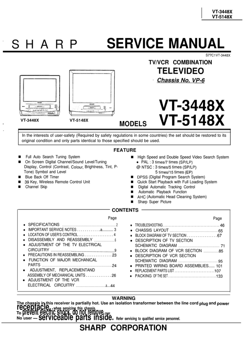
SERVICE
MANUAL
TV/VCR COMBINATION
VIDEO TV
Chassis No.
VP-3
VT-3428X
MODELS
VT-5128X
In the interests of user-safety (Required by safety regulations in some countries) the set should be
restored to its original condition and only parts identical to those specified should be used.
FEATURES
W
TV/VCR Integration for Easy Operation
W
Single Built-in Tuner for Simple Operation
n
Timer Programme Setting by the On-Screen
Display
W
Auto Tracking Control
n
Full
Auto Head Cleaning System
n
On-screen Display with Menu Screen Guidance
H
Wake-Up/Sleep Timer
n
NTSC
Simple Playback
n
2-way Child-Proof Lock
@To
Lock Operation Mode
@To
Lock the Power Off.
n
Ret Index with DPSS (Digital Programme Search
System)
n
Full Auto Play Function
n
Auto Repeat Playback
n
Front input terminals Audio/Video
r
CONTENTS
\
Page
l
SPECIFICATIONS
........................
2
l
IMPORTANT SERVICE NOTES
.............
3
. LOCATION OF USER’S CONTROL
.........
4
.DISASSEMBLY AND REASSEMBLY ........
6
.ADJUSTMENT OF THE TV ELECTRICAL
.
CIRCUITRY
.............................
8
.PRECAUTIONS IN REASSEMBLING .......
15
. FUNCTION OF MAJOR
MECHANICALaPARTS
16
.ADJUSTMENT, REPLACEMENTAND
ASSEMBLY OF MECHANICAL PARTS
ADJUSTMENT OF THE VCR ELECTRICAL.. ..
18
.
CIRCUITRY
............................
42
. TROUBLESHOOTING ...................
45
Page
l
OVERALL SCHEMATIC DIAGRAM
........
57
l
CHASSIS LAYOUT OF TV SECTION
.......
59
.
BLOCK DIAGRAM OF TV SECTION
.......
61
.
DESCRIPTION OF TV SECTION
SCHEMATIC DIAGRAM
.................
65
.
CHASSIS LAYOUT OF VCR SECTION
......
79
l
BLOCK DIAGRAM OF
VCRSECTION
......
81
. DESCRIPTION OF VCR SECTION
SCHEMATIC DIAGRAM
.................
91
.PRINTED WIRING BOARD ASSEMBLIES ...
97
. REPlACEMENT PARTS LIST ............
105
.
PACKINGOFTHESET
.................
134
/
WARNING
The chassis in this receiver is partially hot. Use an isolation transformer between the line cord plug and
power receptacle, when servicing this chassis.
To prevent electric shock, do not remove cover. No user
-
qualified service personnel.
serviceable parts inside. Refer servicing to
SHARP CORPORATION

W-3428X
VT-51
28X
SPECIFICATIONS
I
Model
VT-3428X
VT-51
28X
I-
Reception channels
VHF band
UHF band
Receiving System
VHF :
NZl
-
NZll
CATV
: Sl
-
S41
UHF :
E21
-
E69
44.25
MHz
-
463.25
MHz
(VL:
45.25
-
168.25
MHz/VH:
175.25
-
463.25
MHz)
471.25
MHz
-
885.25
MHz
PAL B/G
AV Input
PAL
Screen
34
cm “Viewable” measured
51
cm “Viewable” measured
diagonally,
90”
deflection diagonally, 90’ deflection
Antenna input
75
ohm unbalanced
Audio output
Max.
1.5
W
I
Speaker
1
8 cm round type x 1
pc
Rated voltage
Rated frequency
Power consumption
77
W
AC220
V
-
240
V
50
Hz
I98W
I
Video cassette format
1
VHS
standard
I
I
Video recording system
1
Two rotary heads, helical scan
I
Number of Video Heads I
2
I
Video signal
PAL
(PlaybacWRecording)
Recording/playing time
480
minutes max. with
E-240
tape
Tape width
12.7
mm
Tape speed
PAL
:
23.39
mm/set
(SP)
11.70
mm/set
(LP)
NTSC
:
33.35
mm/set
(SP
playback only)
16.68
mm/set
(LP
playback only)
11
.12
mm/set
(EP
playback only)
Operating temperature
5°C
to
40°C
Storage temperature
-20°C to
60°C
I
Weight
13.7
kg
Dimensions 388(W)
x
380(H)
x
395(D)
mm
24.2
kg
510(W)
x
499(H)
x
483(D)
mm
Video input
output
Audio input
output
1
.O
Vp-p,
75 ohm
1
.O
Vp-p,
75
ohm
Phono
jack:
0.5
Vrms,
10
kohm
Phono
iack:
0.5
Vrms.
1
kohm
(54%
MOD)
Supplied accessories Operation manual, wireless remote control unit,
R03
(AAA)
battery x 2
*Design and specifications are subject to change without notice.
2

IMPORTANT SERVICE NOTES
Maintenance and repair of this receiver should be done by
qualified service personnel only.
SERVICING OF HIGH VOLTAGE SYSTEM AND
PICTURE TUBE
When servicing the high voltage system, remove static charge from it by
connecting a
10
k ohm Resistor in series with an insulated wire (such as a test
probe) between picture tube
dag
and
2nd
anode lead. (AC line cord should
be disconnected from AC outlet.)
1.
Picture tube in this receiver employs integral implosion protection.
2.
Replace with tube of the same type number for continued safety.
3.
Do not lift picture tube by the neck.
4.
Handle the picture tube only when wearing shatterproof goggles and after discharging
the high voltage completely.
X-RAY
This receiver is designed so that any X-Ray radiation is kept to an absolute
minimum. Since certain malfunctions or servicing may produce potentially
hazardous radiation with prolonged exposure at close range, the following
precautions should be observed:
1.
VT-3428X: When repairing the circuit, be sure not to increase the high voltage to more
than
25.3
kV,
(at beam 0
,A)
for the set.
VT-5128X: When repairing the circuit, be sure not to increase the high voltage to more
than
29.3
kV,
(at beam 0
4)
for the set.
2.
m-3428X: To keep the set in a normal operation, be sure to make it function on
22.0
kV
+
1.5
kV
-
2.0
kv
(at beam
800
fi)
in the case of the set. The set has
been factory
-Adjusted to the above-mentioned high voltage.
VT-5128X:
To keep the set in a normal operation, be sure to make it function on
25.0
kV
,+
1.5
kV
(at beam
1100
,A)
in the case of the set. The set has been
factory
-Adjusted to the above-mentioned high voltage.
mm-
If there-is a possibility that the high
vo,ltage
fluctuates as a result of the repairs, never
forget to check for such high voltage after the work.
3.
D
O
not substitute a picture tube with unauthorized types and/or brands which may cause
excess X-ray radiation.
BEFORE RETURNING THE RECEIVER
Before returning the receiver to the user, perform the following safety
checks.
1.
Inspect all lead dress to make certain that leads are not pinched or that hardware is not
lodged between the chassis and other metal parts in the receiver.
2.
Inspect all protective devices such as non-metallic control knobs, insulating fishpapers,
cabinet backs, adjustment and compartment covers or shields, isolation
resistor-
capacity networks, mechanical insulators etc.
3

P
POWER
BUTTON
SENSOR ARE
EA
’
FOR REMOTE
CONTROL
VT-51
28X
(REARI
i
. .
: :
VIDEO INPUT JACK
-
AUDIO INPUT JACK
-
NOTES:
lUse the RESET button if the
1
1
VIDEOAV
mode (ex. Program
Timer, etc.) cannot be operated.
J
FF
(Forward video
search) BUTTON
STOP/EJECT
BUlTON
REW
(Reverse video
search) BUTTON
POWER/WAKE-UP
TIMER INDICATOR
VOLUME UP/DOWN BUTTONS
REC
BUlTON
CHANNEL UP/DOWN BUl-t-ONS
I
f-4
AESR
l
REC
VVOL
AV
CH
A
MAIN POWER SWITCH
(01)
_J
VIDEO OUT JACK
AUDIO OUT JACK
ANTENNA IN TERMINAL
VT-3428X
MAIN POWER SWITCH
(01)--l
AUDIO OUT JACK
ANTENNA IN TERMINAL
-
I
0
n
2,
-I
0
2
0
In
c
K
51c1
vi
(1
0
z
-I
510
0
I

The remote control lets you operate this product at a distance. Just aim the front of the remote
control at the photoreceptor window situated on the front panel and press the appropriate
Inserting the Batteries
Press
Down
-
Battery
Cover
-4-P
Slide off Slide on
The remote control operates on two
R03
(AAA)
1.5
volt batteries (included). If the remote control does
‘not operate or fails to function normally due to weak
batteries, new batteries can be purchased at elec-
tronics or camera stores.
0
Open the battery cover. (Remove any old
batteries that may be in the remote control.)
@
Insert
ne
w ab
tt
eries and match their polarities
( + and
-
) with the markings inside the compart-
ment.
0
Replace the cover.
l You can set clock and timer recordings using the remote control.
Clock setting: see SETTING THE CLOCK
Timer recording: see RECORDING WITH THE TIMER
NOTES:
l Do not subject the remote control to impact, water or excessive humidity.
l
The remote control may not function if the photoreceptor window of this product is in direct
sunlight or any other strong light. If so, move the product or alter the lighting.
l Incorrect use of batteries may cause them to leak or burst.
l Do not mix old and new batteries, or mix the brands used.
l
Both rechargeable and disposable batteries are available. Read the battery warnings and
do not try to recharge disposable batteries.
l Remove the batteries if the remote control will not be used for a long time.
SENSOR AREA
FOR REMOTE CONTROL
POWER ON/OFF button
(0
I)
WAKE-UP TIMER
SLEEP
TIMER
XIANNEL
SELECT
buttons
TIMER ON/OFF button
EJECT/LOAD button
MUTE button
DISPLAY button
VOLUME ADJUSTMENT buttons
CHANNEL UP/DOWN buttons
(TRACKING buttons)
PROGRAMME button
MENU button
SET button
STOP button
SPILP button
PAUSE/STILL button PLAY button
FF
button
I
F&ward
Video Search
COUNTER RESET button REW button
I
Reverse
Video Search

U--3428X
VT-51
28X
DISASSEMBLY AND
R’EASSEMBLY
n
TV SECTION
1.
Remove the nine screws off the rear cover.
(VT-3428X)
1.
Remove the ten screws off the rear cover. (VT-51 28X)
2.
Disconnect the F connector from the main
PWB
and G connector from the power
PWB
and disconnect
the anode cap and the CRT PWB unit from the CRT.
3.
After disconnect the coating earth from the CRT unit and take out the unit.
4.
Remove the two screws from the main PWB and separate the
PWB
from the video unit.
5.
Remove the three screws from the power
PWB
and separate the
PWB
from the video unit.
(VT-3428X)
(VT-51
28X)
6

DISASSEMBLY AND REASSEMBLY
(Continued)
6.
Remove the CRT PWB,
degaussing
coil connector G and front power switch remote control
PWB.
Place
the main PWB upright.
7.
Reconnect the CRT PWB. Put the main PWB and the VCR unit together as shown below. Keep the front
power switch remote control PWB, speakers and
degaussing
coil connector G off position.
n SERVICING THE
PWBs
<Repairing the TV unit>
Unhook the power PWB and place it on the left
hand of the set. Set up the mother PWB as shown
below.
<Repairing the TV and VCR units>
Unhook the
PWB/mechanism
assembly from the
VCR unit, and place it as shown here. Connect the
cables
(AB),
(AD) and (PC) to the mother
PWB
to
start repairing.
TV Unit
FRONT
-Mother
PWB

W-3428X
VT-51
28X
ADJUSTMENT OF THE
TV ELECTRICAL CIRCUITRY
l PRECAUTIONS
I,
Calling the service mode
(1) Place the set in the stand-by mode.
(2)
Hold down the
CH
UP key
(CH
A)
of the set for 2 seconds or longer and at the same time press the
POWER button (
bl
)
of the set. Now the set is in the service mode.
2.
Clearing the service mode
(1)
There are two ways to clear the service mode. Press the MENU key on the remote control gun
(2) Or place the set in the stand-by mode again.
3.
Display in the service mode
ROM No. in the microprocessor
+
Adjustment item Nos.
01-l
2
L-------d
L---l
data
(O-63,1
O-55,0-3,
O-
1)
r-------------------~
i
1100
0100
0010
1101
I’
+VCJICdata
L---------------,,,,~
*SERVICE MODE :
01
*SERVICE MODE :
02
*SERVICE MODE :
03
*SERVICE
MODE :
04
*SERVICE MODE
:
05
*SERVICE MODE :
06
*SERVICE MODE
:
07
*SERVICE MODE :
08
*SERVICE MODE :
09
*SERVICE MODE :
10
*SERVICE MODE :
11
*SERVICE MODE :
12
T-
RED
INT
=
O-63
GRN
INT
=
O-63
BLUE INT
=
O-63
VERTAMP
= O-63
VERT
LIN
=
O-63
VERT
POS
=
O-63
HOR
PHAS
=
lo-55
HI-VI
= O/l
/2/3
HGAlNl
=0/l
HGAlN2
=0/l
INTSEL
= O/l
CALKILL
=0/l
General adjustment items
Basically fixed
Variable by the VOL
Aff
key
Ls
electable
by the
CH
Aw
key
8

i/T-3428X
VT-51
28X
SCREEN/BACKGROUND ADJUSTMENT
.
Adjusting Conditions
Adjusting Procedures
1.
Screen Adjustment
2.
Reset “video adjust” mode.
1.
Receive the “AV-CH” signal. Keep the blue
1.
Call the service mode and take the step below.
background off. 0
Screen control:
Look at the
VCJ
IC
data on the screen. Adjust the
control so that the
10th
figure from left should
turn from
“1
II
to
“0”.
t
2.
Background Adjustment
1.
Receive “WHITE BALANCE ADJUSTMENT
PATTERN” signal.
2.
In the video adjust mode, adjust the brightness
and contrast.
8
Bright portion:
120
nit
l Dark portion:
20
nit
Keep the colour adjusted at “00”.
3.
Focus Adjustment
1.
Receive “monoscope pattern” signal.
2.
Reset the video adjust mode to have the Video
Normal Position.
To be 0 here too.
f
To turn to 0 here.
1.
Call the service mode and take the step below.
l
Red intensity :
l
Green intensity :
l
Blue intensity :
Pick up the service mode numbers
“2”
and
“3”.
Adjust the
colour
temperature as follows.
12,300”K
(x
=
0.272
+
0.015,
y =
0.275
It
0.015)
The
“CA-100
Minolta
CRT Color Analyzer” should
be used as a colour thermometer.
1.
Adjust the focus control to have the best focus in
the areas between the pattern’s center. and its
both ends.
Adjust point
9

W-3428X
VT-5128X
HORIZONTAL/VERTICAL CIRCUIT ADJUSTMENT
0
Figure
1.
0
Figure
2.
:
‘.
.
:
.
..--
. . . . . . .
.
-.
.
.
:
-.
.
.’
.
_
.
.*
‘.
~~
i
l ‘
.
‘.
$
:
.
,
-.
a*
;
.
-.
.
-. *.-
,
-......-
,
.
:
‘.
:
.
.
Figure
3.
I
Adjusting Conditions
1.
Receive “PAL monoscope pattern” signal.
2.
Reset the video adjust mode to have the Video
Normal position.
Adjusting Procedures
I. Call the service mode and take the steps below.
l
VERT-AMP
(vertical size):
Select the service mode number
“4”.
Adjust the
VERT-AMP
to have 10% overscan.
l
VERT-LIN
(vertical linearity):
Select the service mode number
‘5’.
Adjust the
VERT-LIN
to have optimum vertical linearity. (See
Figs. 1 and
1.)
l
VERT-POS
(vertical center):
Select the service mode number “6”. Adjust the
VERT-POS
so that the vertical center be at the
center of the screen. (See
Fig.
3.)
l
HOR-PHAS
(horizontal center):
Select the service mode number
“7’.
Adjust the
HOR-PHAS so that the horizontal center be at the
center of the screen. ( See
Fig.
4.)
Figure
4.
IO

W-3428X
VL5128X
PURITY ADJUSTMENT
t
a
I
b
Figure A.
Left
.
A..*.-...*.
,
::::::::::::::::::::~.
. . . . . . . . . . . .
:.~:.>:.y*.~;
I
::::~::::::::::::::::::::
s:~:::::::::::::::::~:::
::::::::::::::::$::::
I:::::::::~~::::::::::::::::::
. . . . . . . . . . . . . . .
~~~,:.:.:,~.:.:.:.:.:.:.:
I
:::::::~::~~~.:~:::::
f
I
:::::::::::::::::::::::::::::::
:::::::::::~:~:::::::::
~
:::~~.:::::~:::::::::::::::::
:::~.::~.:::::~~::::~.::
~~
. . . . . . . . . . . . . . .
;
~~~~
\
::::::~::::::::::::::::::::::
::::#:::::::x:::$::.
\
:::::::::~.::::::~::::::..
“::::~::~:y$.:.~
Right
Beam landing equally outwards.
Left
. . . .
..:.:::::::::::::::::..
.::;~:~:~:;
\
..:.:.:.:.:.:.:,~.:.:.:.:.:.
..:.:.:.:.:.:.:.~.:.:.:.:.:
\
:::::::~:::::::::::::::~~:::
:::::::::::::::::::::::::::::::
il
I
:~:::::::::::::::::::::::::::
,
2..
..A........
*.5..*
..A..
;y:y$$:::::::y$$$$:
,
:::::::::::::::::~~::::::::::
:::::::::::::::::::::::::::::
.:.:.:.:.:.:.:.:.:.:.:.~.:.:.
:.:.I:.:.:.:.:.:.:.:.:.:.:.:.:
i.....~......................
i
:::::::::::::::::::::::::::::::
1
::::::::::::::::::::::::~:::::
:::::::::~:::::::::::::::::::
:::::::~:::::::::::::::::::::
:::::::~:::::::::~::::~:::
I
.:.:.ff~:.:.:.:.:.:.~:.:.:.
:.:.:.:.:.:.:.~.:.:.:.:.~
I
:.:.:.~.:.:.:.:.:.:.~~
:.:.:.:.:.~.:5.:.:,:.:.:.:
I
..:.:.:.:.:.:.:.:.:.:.:.:
vZ.*.5..~.5V
A...
*..
s.5..
fS%S.
.
. . .
/
.
y.:,:.:.:.*.v
Figure
B.
Right
.
.v.*.
..
,::$yjg::>g
..~:.:.:.:.~:.:.:.:.:.:.:
\
.:.>>>:.:.p:.>~.~.
\
..:.:.:.:.:.:.:.:.:.:.:.:.:.:.:
:::::::~~.::::::::::~::
:::::::::::::~:::~.:::.
13
1
::~:::::::::::::::~::::::
@Jg$g$~~
g$$J#jgg:$
I
::::::::~::::::::::::~:::::::
I
:::::::::::::::::::::::::::::::
,
:::::::~:::::::::::::::::::::
~~~~.:.
I
:::::::::::::::::::::~::::~::
.~.:.>‘:.:.~.~.;.~.:.:.~.
:.:.:.:.~.:.:.~.:.:.:.:.:
1
::::::;::::::::::::::::::::::::
:~:::~:::::~.::::::~.:::::::;
I
.:.~:,~~:.~..~X.:.:.
s::~::::::::::::::::~::::
I
::::::y$::::::::::::::::
. . . . . . . . . . . .
.7...5......,.....5.,
/
v.;.:.:.~
,
Beam landing shifted to the right.
Left
.
A55..
.
:::::::::::::~~::::..
/
.5..55............55
.:,:.:.:.:.:.:f.:.:.:.:.~.
~:.v.-.~...*
. . .. . . . . . . . . . .
>:.f:.:*:.:.:.:.>:.~.:.:.
;
~~~~
. . . . . . . . . . . . . .z.
.:e:.:.>:.:.:.:.:.:.:.>:.:.:.
1
.r:‘:‘:‘:‘:‘:‘:‘:‘:‘:‘:’
. . . . . . . . . . . . . . .
. . . . . . . . . . . . . . .
.
:.~.:.:.~.:.:.~.:.:.:.:.:
I
. . . . . . . . . . . . . . .
. . . . . . . . . . . . . . .
.
*...*A.
..,.........A.......
. . . . . . . . . . . . . . . .
I
.:.:.:.:.:.:.:.>:.:.:.:.:.:.:.
. . . . . . . . . . . . . . . .
I
I
;
\
[fl
.:.:.:.:.:.:.:.:.:.:.:.>:.:.:.
:.~.:.:.>:.:.:.:s.:.~.:.:
. . . . . . . . . . . . . . .
:.~:.:.:.:.:.:.:.:.:.:.:.f:.:
.:.:.:.:.:.:.:.:.:.:.:.:.:.:...
:.~.:.:.~:.:.:.:.:.:.:.:::
. . . . . . . . . . . . . . .
:*:‘:.:.:.:.:.:.:.:.:.:.:.:.:..
.:.:.:.~.:.:.:.:.:.:.:,p:
. . . . . . . . ...*.....
.
.
. .
. . . . .
.
. . . . . . . . . .
..
....
:.x.:.:.>:.
. . . . . . . . . . . . . . .
.:.:.:.:‘:.:.:.:.~:.:.:.>:
.
:.~.:.:.:.:.:.:.:.:.:.:.:.:.
::$::::::p+:.:.:.:.:...
\
::pJ:$.:$#~..*.
.::~~:$::*$.J$.~
. . . . .
Figure
C.
Right
Beam landing shifted to the left.
Figure
D.
Adjusting Conditions
1.
Before the purity adjustment, warm up the set
with beam current of more than 700
,uA
for
longer than
30
minutes (400 PA for the
14”
model).
2.
Receive the qreen-only signal and adjust the
beam current to about 770
@I
(500
fi
for the
14”
model).
3.
Fully
degauss
the CRT with the
degaussing
coil.
Adjusting Procedures
Notes:
l
Static convergence should be roughly adjusted.
l
The purity magnet should be positioned where
the magnetic field is zero.
Adjustment:
During the adjustment, keep the set facing the east.
1.
Observe the spots “a” and
“b”
(shown in Fig. A)
with a microscope. Adjust the purity magnet to
have these spots at the specified landing
positions.
2.
If the right and left spots are
dqually
deviated
outwards from their landing positions (shown in
Fig.
B),
push the deflection yoke forwards for
proper positioning.
3.
If both the spots are shifted to the right or left
(shown in Figs. C and
D),
adjust the opening
angle of the purity magnet for proper
positioning.
4.
Make sure that the center spot
as
well as the right
and left spots are in their specified landing
positions. Check the four corners of the CRT
screen.
See if all the landing positions are
satisfactory with the Rank “B” specifications.
5.
If any
colour
other than green appears, pull the
deflection coil backwards.
Landing too outwards: Deflection yoke to push
forwards.
Landing too inwards : Deflection coil to
pul
I
backwards.
6.
Receive the monoscope pattern signal.
7.
Set the raster rotation at
“0”
position with the set
facing the east.
Adjustment error: 0
+
2 mm
8.
Tighten up the deflection coil screws.
Tightening torque:
11
+
2 kg
11

VT-3428X
VT-51
28X
CONVERGENCE ADJUSTMENT
Figure a.
RGB BGR
w----------~--L
:
I
I
..I..........
*
. . . .
*
..I.....
.‘.
.
:
I
.
.
:
I
’
I
.
.I
*
-
I
.
*I
RGB
Figure
b.
Figure
c.
Wedge
“a”
Figure
d.
4-pole
magnet
f
6-pole
magnet
,100"
C"
CRT neck
3
.
I
Adjusting Conditions
This adjustment should be performed after
the purity magnet adjustment.
1.
Receive the crosshatch pattern signal.
2.
Set the brightness and contrast controls to the
5/l
0 and 1 O/l 0 positions, respectively.
Adjusting Procedures
STATIC CONVERGENCE
1.
Adjust the opening angle of the
4-pole
magnet
and rotate the magnet to impose the blue line
over the red one.
2.
Adjust the opening angle of the
6-pole
magnet
and rotate the magnet to impose the green line
over the blue one.
DYNAMIC CONVERGENCE
3.
Take the following steps for dynamic
convergence at the edges of the CRT screen.
l
Convergence in Fig a :
Insert the wedge “a” in position, and tilt the
deflection coil upward for correct convergence.
l
Convergence in Fig b :
Insert the wedges
“b”
and
“c’
in position, and tilt
he deflection coil downward for correct
convergence.
l
Convergence in Fig c :
Insert the wedge
“c”
deeper, and tilt the
deflection coil rightward for correct convergence.
l
Convergence in Fig d :
insert the wedge
“b”
deeper, and tilt the
deflection coil
leftward
for correct convergence.
4.
Stick the above wedges on the CRT, and apply
glass tape over them.
5.
Apply lacquer to the deflection yoke screw, the
magnet unit (consisting of purity,
4-pole
and
6
pole magnets)
and’the
magnet unit screw.
Finally receive the red-only signal to make sure
there is no mixture with any other
colour.
Do the
same with the blue-only signal.
Purity magnet
L
Lacquer
12

VT-3428X
VT-51
28X
PERFORMANCE CHECK
1.
A/V Output Checking
Adjusting Point
w
output
1.
Receive the
colour
bar signal
(100%
white
colour
bar, audio : 400 Hz, 100%
(J401)
modulation).
Adjusting Conditions
/
Procedures
2.
Add a
75
ohm terminal resistor to the video output terminal.
3.
Add a
lo-kohm
terminal resistor to the audio output terminal.
The output levels are as follows.
Video output:
1
Vp-p
+
3
dB
(0.71-l
.41
Vp-p)
Audio output:
2.61Vp-p
+
3
dB
(1.85-3.69
Vp-p)
Note:
Make sure the video and audio outputs are as specified.
1.
2.
A/V Input Checking
I
lANinput
(J802
1)
t
1.
Receive the
colour
bar signal.
2.
Feed the external video and audio signals via the
A/V
front jacks.
3.
Using the
CH
Am
key, call the AV mode and make sure the external video and audio
signals are being properly received. (The AV mode is available somewhere between
lch and 40
(max)
ch.)
f
3.
Protector Performance Checking
Protector
Performance
1.
Receive the monoscope pattern signal.
2.
Apply
20V
from the constant-voltage power supply to the cathode of
D607
(TP603:
no
symbol on the
PWB)
and make sure the protector is not activated.
3.
Feed 25V in the same way and make sure the protector is activated.
Note:
To reset the protector, press the
RESETkey.
4.
Beam Protector Performance Checking
Beam
Protector
Performance
1.
Receive the monoscope pattern signal.
2.
Ground any of the
R,
G and B cathodes on the CRT PWB.
3.
Make sure the protector is activated immediately.
Note:
To reset the beam protector, press the RESET key.
13

W-3428X
VT-51
28X
PERFORMANCE CHECK
(Continued)
5.
Blue Background Checking
Adjusting Point
Adjusting Conditions
/
Procedures
Blue
1.
In the SET UP mode, select the BLUE SCREEN function.
background
2.
Turn on the function. With any signal input, make sure the background is blue.
Make sure also that the audio is mute.
3.
Turn off the function and make sure the blue background disappears.
c
6.
Record Index Checking
Record
index
1.
In the SET UP mode, select the
REC
INDEX function.
2.
Turn on the function to make recording. (Make sure the clock has been preset.)
3.
Check the recorded contents.
Note:
Make
sure
the channel and time
are
recoded.
14

VT-3428X
VT-51
28X
PRECAUTIONS IN REASSEMBLING
MOUNTING THE
CASSETTE
CONTROLLER
Initial setting is indispensable
before placing the cassette controller in the mechanism. The initial setting is
made in two ways; electrical and mechanical.
Electrical setting:
Make a short-circuit between TP8804 and TP8805, both located at the center on your side on VCR
PWB,
with a
22
ohm resistor and be sure that the mechanism is back to its initial setting position
(*l).
Now place
the cassette controller in position. (This method is used when the mechanism has been already set on its
PWB.)
Cassette control
r----
drive gear
Phase matching point
Mechanical setting:
Turn the loading motor’s
pulley feed gear using a
screwdriver and be sure
that the mechanism is
back to its initial setting
position
(*l).
Now place
the cassette controller in
position. (This method is
applicable for the
mechanism alone.)
COUPLING THE MECHANISM TO THE
PWB
Match the mechanism’s projections with the two symbols (round reference and oval sub-reference) on the
VCR PWB. Place the mechanism straight down in position with due care so that the mechanism chassis’s
outer edges should not damage any parts nearby.
Tighten up the two screws (one for fixing the mechanism and the head amplifier shield, the other on the
VCR
PWB’s
soldering side and located near the loading motor) to fix the mechanism and VCR PWB.
Reconnect the
FFC
cables
(EB,
EF
and EH) and harnesses (ED and
EG)
between the mechanism and VCR
PWB.
Parts to pay attention to:
Start and end
.sensors:
Q8803,Q8804
Record tip switch: 58801
Take special care of the MC-EC connector
(board
to
board) between
the mechanism
and VCR
PWB.

W-3428X
I
VT-5128X
t
FUNCTION OF MAJOR MECHANICAL PARTS
(TOPVIEW)
19
Drum Motor
P
20
Auto Head Cleaner
Ass’y
P
f
Take-Up Pole
/
Base Ass’y A/C Head
Ass’y
Drum
Ass’v
m
Full Erase
Head
Ass’y
Supply Pole
Base
Ass’y
Main Supply
Brake Lever
Tension
Arm
Ass’y
SUPPlY
Pinch Roller
Lever
Ass’y
Reverse Guide
Pinch Drive Car
Pinch Drive
Lever
Ass’y
Main Take-Up
Brake Lever
Cassette
Housing
Drive Gear
Take-Up
Lock Lever
Reel Disk
@
Loading
Motor
n
No.
Function
No.
Function
1.
Full erase head
ass’y 13.
Erase the whole records on the tape in the recording Reverse guide
mode. Pulls out the tape and controls the tape drive train
height with the upper and lower guides.
3.
7.
Tension arm
ass’y
Detects the tension of tape while running, and brakes
the supply reel disk via the tension band.
Main supply brake lever
Brakes the supply reel disk to prevent tape slackening
when the unit is stopped in fast forward or rewind
mode.
16.
Pinch roller lever
ass’y
Press-fits tape to the capstan during tape running-The
right protrusion switches the clutch of the cassette
housing control assembly in “tape eject”, and makes
the mechanism eject tape,
9. Main take-up brake lever
18.
Loading motor
Brakes the take-up reel disk to prevent tape slackening A motive power which drives the mechanism. It
when the unit is stopped in fast forward or rewind transmits the power to the master cam and cassette
mode. housing control assembly .
16

FUNCTION OF MAJOR MECHANICAL PARTS
(BOTTOM VIEW)
P
9
Take-up
Loading Gear
Capstan
DD
Motor
3
o-
Reel Belt
@,
Slow
Brake Lever
1
o-
Master Cam
@,
Cassette Housing
Drive Gear
Connect Gear 5
o++
Clutch Gear
@
0
8
Shifter
\
0
10
Clutch Connect Arm
0
6
Reel Pulley
No.
Function
No.
Function
1.
Slow brake lever
6.
Reel pulley
Gets in contact with the capstan
D.D.
motor linking to Transmits the power of the capstan
D.D.
motor to the
the master cam in the slow still mode, and brakes it to a reel disk via the reel idler.
certain degree.
3.
Capstan
D.D.
motor
A motive power which runs the tape. It transmits the
power via the reel belt.
8.
Shifter
Transmits the operation of the master cam to break
and loading gear.
4.
Reel belt
Transmits the power to run the tape to the reel pulley.
9.
Take-up loading gear
Shifts the take-up pole base and guide roller via the
loading relay gear, and applies the tape around the
drum assembly, as well as transmits the power to the
supply loading gear.

VT-3428X
VT-51
28X
ADJUSTMENT, REPLACEMENT AND ASSEMBLY OF
MECHANICAL UNITS
_
Here we will describe a relatively simple service
work in the field, not referring to the more
complicated repairs which would require the use of
special equipment and tools (drum assembly
replacement, for example).
We are sure that the easy-to-handle tools listed
below would be more than handy for periodical
maintenance to keep the machine in its original
working condition.
TbOLS
NECESSARY FOR ADJUSTING THE MECHANICAL UNITS
The following tools are required for proper service and satisfactory repair.
-
0.
-
1
-
2
-
3
-
4
-
5
-
6
-
7
-
a
-
9
-
11
b
Jig Item
Part No. Code
Reel Disk Height Adjusting Jig
JiGRH0002
BR
Configuration
42
Master Plane Jig
I
JiGMPOOOl
BY
I I
A/C Head Tilt Adjusting Jig 9DAACH-A323U
BX
Gauge Head
Cassette Torque Meter
acD
JiGTH0006
AW
f!3
JiGVHT-063
CZ
Tension Gauge (3009)
Tension Gauge (2.0kg)
JiGSG0300
BF
JiGSG2000
BS
Hex Wrench (0.9mm)
I
1
I
JiGHW0009
AE
Hex Wrench (1.2mm)
Hex Wrench (1.5mm)
JiGHWOOl2
AE
JiGHWO015
AE
Alignment Tape (PAL)
VROCPSV
VROUBZFS
Tension Gauge Adapter
/
JiGADP003
/
BK
1
Remarks
These Jigs are used for checking and
adjusting the reel disk height.
This Jig is used for setting the A/C
head tilt.
These Jigs are used for checking and
adjusting the torque of take-up and
supply reel disks.
This cassette torque meter is used
for checking and adjusting the
torque of take-up for measuring
tape back tension-
There
are two gauges used
for the
tension measurements, 300
g
and
2.0 kg.
These Jigs are used for loosening or
tightening special hexagon type
screws.
These tapes are especially used for
electrical fine adjustment.
This Jig is used with the tension
gauge. Rotary transformer
clearance adjusting jig.
18

No.
Jig Item
Part No. Code
Configuration
Remarks
12
Special Bladed Screwdriver
JiGDRiVERH-4
Ap
This screwdriver is used for adjusting
the guide roller height.
This is used to screw down
resin-
14
Torque Driver JiGTDl200
CB
made parts: the specified torque is
5
-
kg-
This Jig is used for height
adjust-
JiGDRiVER
1
O-7
AS
ment
of the A/C head and X-
/
’
position.
Box Driver JiGDRiVER 10-4 AV
:
This Jig is used for replacement of
15
the
SI
roller.
C
JiGDRiVER
lo-55
AR This Jig is used for height adjust-
ment of the reverse guide.
17
Reverse Guide Height
JiGRVGH-F18
BU
This Jig is used for height
adjust-
Adjusting Jig
ment
of the reverse guide.
19

W-3428X
W-51
28X
MECHANICAL PARTS REQUIRING PERIODICAL INSPECTION
Use
the following table as a guide to maintain the mechanical parts in good operating condition.
500
1000 1500 2000
hrs. hrs. hrs. hrs. Possible symptom encountered Remarks
Guide roller
ass’y
Supply impedance roller
(inner hole and shaft)
Supply impedance roller flange
Retaining guide
Slant pole
Video head (upper/Lower drum
ass’y)
Full-erase head
A/C head
Capstan
D.D.
Motor
Pinch roller
Reel belt
Tension band
ass’y
Loading Motor
Reel idler
ass’y
Reel
pully
ass’y
Clutch gear
ass’y
Main supply/take-up brake levers
AHC
(Automatic Head Cleaner)
q q q 0 Abnormal rotation or
significant vibration
Cl
q cl 0 requires replacement.
cl
q
Lateral noises Clean with pure high
Head occasionally blocked quality isopropyl alcohol.
cl
cl
cl
cl
Clean tape contact part
cl cl cl El with the specified cleaning
liquid.
cl q
cl
0
Poor S/N ratio, no
colour
El
0
Cl
0 Cl 0 Cl Poor flatness of the envelope with
alignment tape Clean tape contact area
q q
0
0
Poor
colour,
beating with the specified cleaning
liquid.
Cl
0
cl 0Sound too small or distorted
cl q
0
0
No tape running, uneven
colour
cl q
cl
0 No tape running, tape slack Clean rubber and rubber
contact area with the
III
0No tape running, tape slack, no
fast forward/rewind motion specified cleaning liquid.
0Cassette not loaded or unloaded
.
0
0No tape running
q
A
00
0
0 Tape slack
Replace the roller of the
cleaner when it wears
0 0 down.
Just change the
AHC
roller
assembly for new one.
NOTE:
0:
Part replacement.
Cl
:
Cleaning (For cleaning, use a lint-free cloth dampened with pure isopropyl alcohol).
A:
Oil refilling (The indicated point should be lubricated with high quality spindle oil every
1000
hrs).
If the reading is out of the specified value, clean or replace the part.
,
20
Other manuals for VT-3428X
1
This manual suits for next models
1
Table of contents
Other Sharp TV VCR Combo manuals

Sharp
Sharp 13VT-K100 User manual

Sharp
Sharp 37VT-26H User manual

Sharp
Sharp 13VT-N100 User manual

Sharp
Sharp 13VT-CR10 User manual

Sharp
Sharp 13VT-L200 User manual

Sharp
Sharp VT-G14 User manual

Sharp
Sharp 13VT-N200 User manual

Sharp
Sharp VT-3448X User manual

Sharp
Sharp 13VT-R100 User manual

Sharp
Sharp 37VT-24H User manual