Sharp 13VT-K100 User manual

13VT-K100/150
13VT-CK10
1
SERVICE MANUAL
CONTENTS
Page
»IMPORTANT SERVICE SAFETY PRECAUTION....................................................................................2
»ELECTRICAL SPECIFICATIONS ............................................................................................................ 6
»LOCATION OF USER’S CONTROL ........................................................................................................ 7
»DISASSEMBLY AND REASSEMBLY ......................................................................................................9
»INSTALLATION AND SERVICE INSTRUCTIONS.................................................................................12
»PRECAUTIONS IN REASSEMBLING ................................................................................................... 17
»FUNCTION OF MAJOR MECHANICAL PARTS....................................................................................18
»ADJUSTMENT, REPLACEMENT AND ASSEMBLY OF MECHANICAL UNITS ...................................20
»ADJUSTMENT OF THE VCR ELECTRICAL CIRCUITRY.....................................................................40
»TROUBLESHOOTING ........................................................................................................................... 42
»CHASSIS LAYOUT ................................................................................................................................ 55
»BLOCK DIAGRAM OF TV SECTION.....................................................................................................57
»BLOCK DIAGRAM OF VCR SECTION ................................................................................................. 59
»OVERALL SCHEMATIC DIAGRAM.......................................................................................................69
»DESCRIPTION OF SCHEMATIC DIAGRAM......................................................................................... 71
»PRINTED WIRING BOARD ASSEMBLIES ........................................................................................... 83
»REPLACEMENT PARTS LIST............................................................................................................... 89
»PACKING OF THE SET ....................................................................................................................... 108
In the interests of user-safety (Required by safety regulations in some countries ) the set should be restored to its
original condition and only parts identical to those specified should be used.
S48O413VT-K10
MODELS
13VT-K100/150
13VT-CK10
TV/VCR COMBINATION
Chassis No. B97B
SHARP CORPORATION This document has been published to be used for
after sales service only.
The contents are subject to change without notice.

13VT-K100/150
13VT-CK10
2
IMPORTANT SERVICE SAFETY PRECAUTION
Service work should be performed only by qualified service technicians who are
thoroughly familiar with all safety checks and servicing guidelines which follow:
SERVICING OF HIGH VOLTAGE SYSTEM
AND PICTURE TUBE
When servicing the high voltage system,
remove the static charge by connecting a
10k ohm resistor in series with an insulated
wire (such as a test probe) between the pic-
ture tube ground and the anode lead. (AC
line cord should be disconnected from AC
outlet.)
1. Note that the picture tube in this receiver employs
integral implosion protection.
2. Replace with tube of the same type number for
continued safety.
3. Do not lift picture tube by the neck.
4. Handle the picture tube only when wearing
shatterproof goggles and after discharging the high
voltage anode completely.
CAUTION: FOR CONTINUED
PROTECTION AGAINST A
RISKOF FIRE, REPLACE
ONLY WITH SAME TYPE 4A-
125V FUSE.
4A 125V
WARNING
1. For continued safety, no modification of any circuit
should be attempted.
2. Disconnect AC power before servicing.
3. Semiconductor heat sinks are potential shock
hazards when the chassis is operating.
4. The chassis in this receiver has two ground systems
whichare separated byinsulation material.The non-
isolated (hot) ground system is for the B+ voltage
regulator circuit and the horizontal output circuit.The
isolatedground systemis for the low B+ DCvoltages
and the secondary circuit of the high voltage
transformer.
To prevent electrical shock use an isolation
transformer between the line cord and power
receptacle, when servicing this chassis.
X-RADIATION AND HIGH VOLTAGE LIMITS
1. Be sure all service personnel are aware of the
procedures and instructions covering X-radiation.
The only potential source of X-ray in current solid
state TV receivers is the picture tube. However, the
picture tube does not emit measurable X-Ray
radiationifthe highvoltageis asspecifiedin the "High
Voltage Check" instructions.
It is only when high voltage is excessive that X-
radiation is capable of penetrating the shell of the
picture tube including the lead in glass material. The
important precaution is to keep the high voltage
below the maximum level specified.
2. It is essential that servicepersonel have available at
all times an accurate high voltage meter.
The calibration of this meter should be checked
periodically.
3. High voltage shouldalways bekept atthe rated value
-no higher. Operation at higher voltages may cause
a failure of the picture tube or high voltage circuitry
and;also, under certain conditions, may produce
radiation that exceeds specifications.
4. When the highvoltage regulatoris operating properly
there is no possibility of an X-radiation problem.
Every time a color chassis is serviced, the
brightness should be tested while monitoring the
high voltage with a meter to be certain that the high
voltagedoes not exceedthe specified value and that
it is regulating correctly.
5. Do not use a picture tube other than that specified
ormake unrecommended circuit modifications tothe
high voltage circuitry.
6. When trouble shooting and taking test
measurements on a receiver with excessive high
voltage, avoid being unnecessarily close to the
receiver.
Donot operate thereceiver longer thanis necessary
to locate the cause of excessive voltage.

13VT-K100/150
13VT-CK10
3
BEFORE RETURNING THE RECEIVER
(Fire & Shock Hazard)
Before returning the receiver to the user, perform
the following safety checks.
12345678901234567890123456789012123456789012345678901234567890121234567890123456789012345678901212
1
234567890123456789012345678901212345678901234567890123456789012123456789012345678901234567890121
2
12345678901234567890123456789012123456789012345678901234567890121234567890123456789012345678901212
SAFETY NOTICE
Many electrical and mechanical parts in television
receivers have special safety-related characteristics.
These characteristics are often not evident from visual
inspection, nor can protection afforded by them be
necessarily increased by using replacement
components rated for higher voltage, wattage, etc.
Replacement parts which have special safety
characteristics are identified in this manual; electrical
components having such features are identified by " å
" and shaded areas in the Replacement Parts Lists and
Schematic Diagrams.
AC
VOLTMETER
1.5k ohm
10W
0.15µF
TEST PROBE
TO EXPOSED
METAL PARTS CONNECT TO
KNOWN EARTH
GROUND
1. Inspect all lead dress to make certain that leads are
not pinched or that hardware is not lodged between
the chassis and other metal parts in the receiver.
2. Inspect all protective devices such as non-metallic
control knobs, insulating materials, cabinet backs,
adjustment and compartment covers or shields,
isolation resistor-capacity networks, mechanical
insulators, etc.
3. To be sure that no shock hazard exists, check for
leakage current in the following manner.
»Plug the AC cord directly into a 120 volt AC outlet,
(Do not use an isolation transformer for this test).
»Using to clip leads, connect a 1.5k ohm, 10 watt
resistor paralleled by a 0.15µF capacitor in series
with all exposed metal cabinet parts and a known
earth ground, such as electrical conduit or electrical
ground connected to earth ground.
»Use anAC voltmeter having with 5000 ohm per volt,
orhigher, sensitivity to measurethe AC voltagedrop
across the resistor.
For continued protection, replacement parts must be
identical to those used in the original circuit. The use of
a substitute replacement parts which do not have the
samesafetycharacteristics asthefactory recommended
replacement parts shown in this service manual, may
create shock, fire, X-radiation or other hazards.
»Connectthe resistor connectionto all exposed metal
parts having a return to the chassis (antenna, metal
cabinet, screw heads, knobs and control shafts,
escutcheon, etc.) and measure theAC voltage drop
across the resistor.
AII check must be repeated with the AC line cord
plug connection reversed. (If necessary, a non-
polarized adapter plug must be used only for the
purpose of completing these check.)
Anycurrent measuredmust notexceed 0.5milliamp.
Any measurements not within the limits outlined
above are indicative of a potential shock hazard and
corrective action must be taken before returning the
instrument to the customer.
IMPORTANT SERVICE SAFETY PRECAUTION
(Continued)
12345678901234567890123456789012123456789012345678901234567890121234567890123456789012345678901212
1
234567890123456789012345678901212345678901234567890123456789012123456789012345678901234567890121
2
12345678901234567890123456789012123456789012345678901234567890121234567890123456789012345678901212

13VT-K100/150
13VT-CK10
4
PRECAUTIONS A PRENDRE LORS DE LA REPARATION
Ne peut effectuer la réparation qu' un technicien spécialisé qui s'est parfaitement
accoutumé à toute vérification de sécurité et aux conseils suivants.
LIMITES DES RADIATIONS X ET DE LA
HAUTE TENSION
1. Tout le personnel réparateur doit être instruit des
instructions et procédés relatifs aux radiations X.
Le tube-image, seule source de rayons X dons les
téleviseurs transistorisés, n'émet pourtant pas de
rayonsmesurables sila hautetension estmaintenue
à un niveau préconisé dans la section "Vérification
de la haute tension".
C'est seulement quand la haute tension est
excessive que les rayons X peuvent entrer dans
l'enveloppe du tube-image y compris le conducteur
deverre.Il est importantdemaintenir lahautetension
en-dessous du niveau spécifié.
2. Il est essentiel que le réparateur ait sous la main un
voltmètre à haute tension qui doit être
périodiquement étalonné.
3. La haute tension doit toujours être maintenue à la
valeur de régime-et pas plus haute. L'opération à
des tensions plus élevées peut entraîner une panne
du tube-image ou du circuit à haute tension et, dans
certaines conditions, peut entraîner une radiation
dépassant les niveaux préscrits.
4. Quand le régulateur à haute tension fonctionne
correctement, il n'y a aucun problème de radiation
X. Chaque fois qu'un châssis couleurs est réparé, la
luminosité doit être examinée bout en contrôlant la
haute tension à l'aide d'un voltmètre pour s'assurer
que la haute tension ne dépasse pas la valeur
spécifiée et qu'elle soit correctement réglée.
5. Ne pas utiliser un tube-image autre que celui spécifié
et ne pas effectuer de modifications déconseillées
du circuit à haute tension.
6. Lors de la recherche des pannes et des mesures
d'essai sur un récepteur qui présente une haute
tension excessive, éviter de s'approcher inutilement
du récepteur.
Nepas faire fonctionnerle récepteur pluslongtemps
que nécessaire pour localiser la cause de la tension
excessive.
AVERTISSEMENT
1. N'entreprendre aucune modification de tout circuit.
C'est dangereux.
2. Débrancher le récepteur avant toute réparation.
3. Les déversoirs thermiques à semi-conducteurs
peuvent présenter un danger de choc électrique
lorsque le réceqteur est en marche.
4. Le châssis dece récepteura deux systèmesde mise
à la terre qui sont séparés par un matériau isolant.
Le système de mise à la terre non-isolée (chaud)
est pour le circuit du régulateur de tension B+ et le
circuit de sortie horizontale. Le système de mise à
la terre isolé est pour les basses tensions C. C. B+
et le circuit secondaire du transformateur de haute
PRECAUTION:POUR LA
PROTECTION CONTINUE
CONTRE LES RISQUES
D'INCENDIE,REMPLACER LE
FUSIBLEPAR UNFUSIBLE DE
MEME TYPE 4A-125V.
4A 125V
tension.
REPARATION DU SYSTEMEAHAUTE TEN-
SION ET DU TUBE-IMAGE
Lors de la réparation de ce systéme,
supprimer la charge statique en branchant
une résistance de 10 k en série avec un fil
isolé (comme une sonde d'essai) entre la
mise à la terre du tube-image et le fil
d'anodel.(Le corden d'alimentation doit être
retiré de la prise murale.)
1. Il est à noter que le tube-image de ce récepteur est
intégralement protégé contre l'implosion.
2. Par mesure de sécurité, changer le tube-image pour
un tube du même numéro de type.
3. Ne pas lever le tube-image par son col.
4. Ne manipuler le tube-image qu'en porant des
lunettes incassables et qu'après avoir déchargé
totalement la haute tension.

13VT-K100/150
13VT-CK10
5
VERIFICATIONS CONTRE L'INCEN-DIE ET
LE CHOC ELECTRIQUE
Avant de rendre le récepteur à l'utilisateur, effectuer
les vérifications suivantes.
»Toucher avec lasonde d'essailes piècesmétalliques
exposées qui présentent une voie de retour au
châssis (antenne, coffret métallique, tête des vis,
arbres de commande et des boutons, écusson, etc.)
et mesurer la chute de tension CA en-travers de la
résistance.
Toutes les vérifications doivent être refaites après
avoir inversé la fiche du cordon d'alimentation. (Si
nécessaire, une prise d'adpatation non polarisée
peut être utilisée dans le but de terminer ces
vérifications.)
Tous les courants mesurés ne doivent pas dépasser
0,5 mA.
Dans le cas contraire, il y a une possibilité de choc
électrique qui doit être supprimée avant de rendre
le récepteur au client.
12345678901234567890123456789012123456789012345678901234567890121234567890123456789012345678901212
1
234567890123456789012345678901212345678901234567890123456789012123456789012345678901234567890121
2
12345678901234567890123456789012123456789012345678901234567890121234567890123456789012345678901212
12345678901234567890123456789012123456789012345678901234567890121234567890123456789012345678901212
1
234567890123456789012345678901212345678901234567890123456789012123456789012345678901234567890121
2
12345678901234567890123456789012123456789012345678901234567890121234567890123456789012345678901212
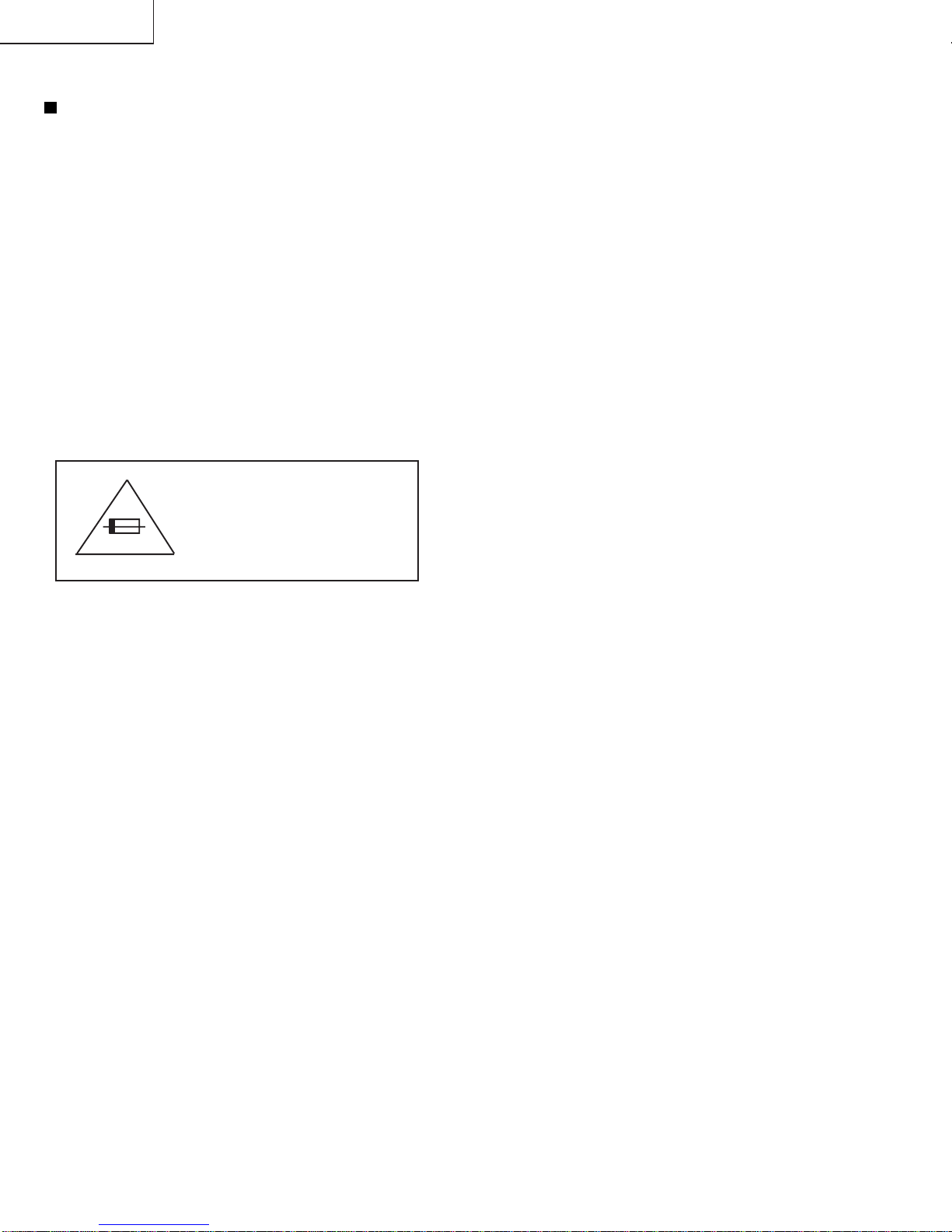
AVIS POUR LA SECURITE
De nombreuses pièces, électriques et mécaniques,
dans les téléviseurs présentent des caractéristiques
spéciales relatives à la sécurité, qui ne sont souvent
pas évidentes à vue. Le degré de protection ne peut
pas être nécessairement augmentée en utilisant des
piècesde remplacement étalonnéespour hautetension,
puissance, etc.
Les pièces de remplacement qui présentent ces
caractéristiques sont identifiées dans ce manuel; les
piècesélectriques qui présententces particularités sont
PRECAUTIONS A PRENDRE LORS DE LA REPARATION
(Suite)
1. Inspecter tous les faisceaux decâbles pours'assurer
que les fils ne soient pas pincés ou qu'un outil ne
soit pas placé entre le châssis et les autres pièces
métalliques du récepteur.
2. Inspecter tous les dispositifs de protection comme
les boutons de commande non-métalliques, les
isolants, le dos du coffret, les couvercles ou
blindages de réglage et de compartiment, les
réseaux de résistance-capacité, les isolateurs
mécaniques, etc.
3. S'assurer qu'il n'y ait pas de danger d'électrocution
en vérifiant la fuite de courant, de la facon suivante:
»Brancherle cordon d'alimentationdirectem-ent àune
prise de courant de 120V. (Ne pas utiliser de
transformateur d'isolation pour cet essai).
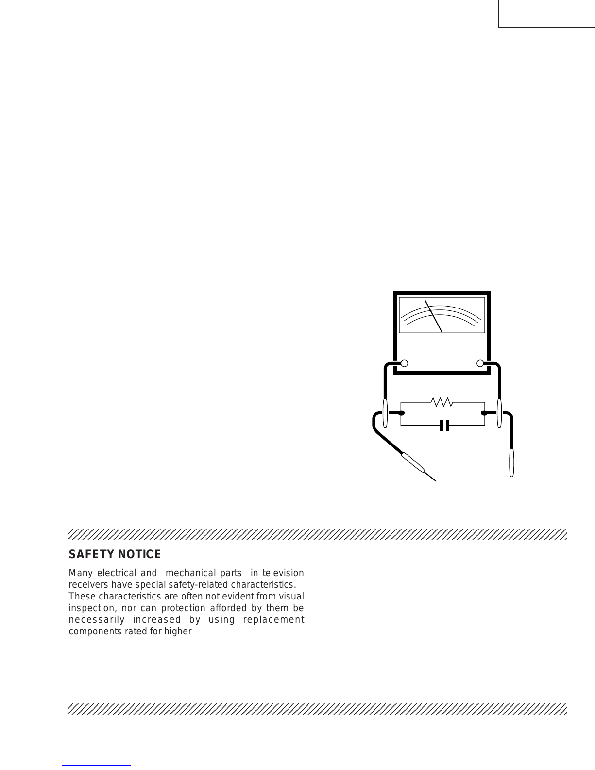
»Al'aidede deux filsàpinces, brancherunerésistance
de1,5k 10 watts enparallèleavec uncondensateur
de0,15µFen sérieavectoutes lespiècesmétalliques
exposées du coffret et une terre connue comme une
conduite électrique ou une prise de terre branchée
à la terre.
»Utiliser un voltmètre CA d'une sensibilité d'au moins
5000 /Vpour mesurerla chute de tension entravers
de la résistance.
AC
VOLTMETER
1.5k ohm
10W
0.15µF
TEST PROBE
TO EXPOSED
METAL PARTS CONNECT TO
KNOWN EARTH
GROUND
SONDE D'ESSAI
AUX PIECES
METALLIQUES
EXPOSEES
Voltmètre CA
identifiées par la marque " å" et hachurées dans la
liste des pièces de remplacement et les diagrammes
schématiques.
Pour assurer la protection, ces pièces doivent être
identiques à celles utilisées dans le circuit d'origine.
L'utilisation de pièces qui n'ont pas les mêmes
caractéristiques que les pièces recommandées par
l'usine, indiquées dans ce manuel, peut provoquer des
électrocutions, incendies, radiations X ou autres
accidents.
BRANCHER A UNE
TERRE CONNUE

13VT-K100/150
13VT-CK10
6
ELECTRICAL SPECIFICATIONS
TV SECTION POWER INPUT: 120 V AC 60 Hz
POWER RATING: 65 W
PICTURE SIZE
Width: 37.8 cm
Height: 38.7 cm
Depth: 38.2 cm
CONVERGENCE: Magnetic
SWEEP DEFLECTION: Magnetic
FOCUS: Hi-Bi-Potential Electrostatic
INTERMEDIATE FREQUENCIES
Picture IF Carrier Frequency: 45.75 MHz
Sound IF Carrier Frequency: 41.25 MHz
Color Sub-Carrier Frequency: 42.17 MHz (Nominal)
AUDIO POWER OUTPUT RATING: 0.8 W (at 10% Distortion)
SPEAKER
Size: 5 ×9 cm (2" ×31/2")
Voice Coil Impedance: 16 ohm at 400 Hz
VHF/UHF ANTENNA INPUT IMPEDANCE: 75 ohm unbalanced
TUNING RANGES
VHF-Channels: 2 thru 13
UHF -Channels: 14 thru 69
CATV Channels: 1,14 thru 125 (EIA, Channel Plan)
VCR SECTION Format: VHS Standard
Video Recording System: Rotary Two-Head Helical Scanning
Number of Video Heads: 2 pcs.
Video Signal Standard: NTSC Color System
Tape Width: 12.7mm (1/2inch)
Tape Speed: (SP)33.35mm/sec (1.31 i.p.s)
(LP)16.67mm/sec (0.66 i.p.s)
Play back only
(EP)11.12 mm/sec (0.44 i.p.s)
Maximum Recording Time: (SP)160 min (T-160)
(EP)480 min (T-160)
Video Input: 0.5 to 2.0 Vp-p, 75 ohm unbalanced
Audio Input: -8 dB, 47k ohm unbalanced (0 dB-0.775 Vrms)
Operating Temperature: 5°C to 40°C (41°F to 104°F)
Storage Temperature: -20°C to 60°C (-4°F to 140°F)
Specifications are subject to change without prior notice.

13VT-K100/150
13VT-CK10
7
Description Of Controls
FRONT
LOCATION OF USER'S CONTROL
REAR

13VT-K100/150
13VT-CK10
8
Location Of Control’s Buttons (Remote Control)
LOCATION OF USER'S CONTROL (Continued)
Remote Control Battery Installation
Before using the television, prepare the Remote Control.
Battery Cover
Pull Up
»Remote the battery cover as shown and insert two batteries (size
“AA”) making sure the polarity matches the (+) and (–) marks inside
the battery conpartment.

13VT-K100/150
13VT-CK10
9
1. Remove the 7 rear cover fixing screws and detach the rear cover.
2. Take out the anode cap, CRT PWB, connectors K and M, coating earth, Speaker chip fixing screws and others.
3. Take out the main PWB unit and the VCR unit.
4. Remove the 5 VCR fixing screws, and detach the shielding case.
DISASSEMBLY AND REASSEMBLY
1
4
3
2
K
M

13VT-K100/150
13VT-CK10
10
5. Remove the 4 cassette housing control fixing screws, and detach the cassette housing control.
6. Remove the 2 mechanism chassis angle fixing screws, and remove the 1 head amp shielding case fixing screw.
7. Remove the 3 mechanism chassis fixing screws, and detach the mechanism chassis from the main PWB.
8. Remove the 2 main PWB fixing screws, and detach the main PWB.
9. Remove the 2 power PWB fixing screws, and detach the power PWB
DISASSEMBLY AND REASSEMBLY (Continued)
7
7
6
89
5

13VT-K100/150
13VT-CK10
11
DISASSEMBLY AND REASSEMBLY (Continued)
For servicing any of the components inside, disconnect the lead dressing holder. Position the main PWB unit upright
as shown below and connect the leads for starting the services.
GC YC
M
K
SYC
FRONT
SP
PO
PG
PG
S
GC
PO

13VT-K100/150
13VT-CK10
12
INSTALLATION AND SERVICE INSTRUCTIONS
Note: (1) When performing any adjustments to resistor controls and transformers use non-metallic
screwdriver or TV alignment tools.
(2) Before performing adjustment, TV set must be on at least 15 minutes.
HIGH VOLTAGE CHECK
High voltage is not adjustable but must be checked
to verify that the receiver is operating within safe
and efficient design limitations as specified checks
should be as follows:
1. Connect an accurate high voltage meter between
ground and anode of Picture tube.
2. Operate receiver for at least 15 minutes at 120VAC
line voltage, with strong air signal or properly tuned
in test signal.
3. Set to Service mode on, "Mute" and bus data 1(Y-
mute on).
4. The voltage should be approximately 25.4kV (atzero
beam). If a correct reading cannot be obtained,
check circuitry for malfunctioning components.
After the voltage test, "Mute" and bus data "0" (Y-
mute off).
CIRCUIT PROTECTION
Thereceiveris protected bya4.0A fuse (F701),mounted
on PWB-A, wired into one side of the AC line input.
X-RADIATION PROTECTOR CIRCUIT
TEST
After service has been performed on the horizontal
deflection system, high voltage system, or B+ system,
test the X-Radiation protector circuit to ascertain proper
operation as follows:
1. Apply 120V AC using a variac transformer for
accurate input voltage.
2. Allow for warm up and using the remote controller,
set the brightness level and contrast level to
maximum.
3. Check the voltage of test point TP653. (It’s voltage
should be about 10.1V DC.)
4. Apply external 13.1V DC at TP653 by using an
externalDC supply. The increased voltagewill cause
the horizontal oscillator to stop and the TV to shut
off.
5. To re-start the oscillator, remove the external DC
power supply and short together TP651 andTP652.
Once the TV set operates normally again, remove
the short between TP651 and TP652.

13VT-K100/150
13VT-CK10
13
1. Service mode
Berfore putting unit into the service mode, check,
that customer adjustments are in the normal mode,
use the reset function in the video adjust menu to
ensure customer controls are in their proper (reset)
position.
To enter the service mode
Plug in a television set, during push S2507 (CH-up).
When successfuly entered, the service mode will be
displayed as shown in Figure A.
To exit service mode
Turn off the power or unplug the set.
2. Adjustment Item selection
Once in the service mode, press the channel up or
channel down button on the remote controller or at
theset (Table-A.). Select theitem youwish toadjust.
3. Data number selection
Press the volume up or down button to adjust the
data number in the upper right hand side of the
screen.
PICTURE: 16 2
Figure A.
The K-series SHARP TV/VCR COMBINATION have most of the analog setup adjustments eliminated. Coil and
variable resistor adjustments are now performed digitally by using the remote transmitter or set’s volume
and channel change function buttons.
Note: There are still a few analog adjustments in the K-series such as 120V adjust, focus, master screen
voltage and coils in the picture IF/detector circuit.
Follow the steps below whenever service adjustment is required. See table "B" to determine if service
adjustments are required.

13VT-K100/150
13VT-CK10
14
Table - B
PART
REPLACED ADJUSTMENT
NECESSARY UNNECESSARY NOTE
IC2001 X
IC401 X
IC2101 X
CRT X
ADJUSTMENT
ITEM DATA
INTIAL VALUE RANGE ADJUSTMENT
COMMENTS
*No adjustment is required due to proper setting being made by IC2001 automatically.
Table - A
PICTURE 16 0~63
TINT 39 0~77
COLOR 13 0~63
BRIGHT 32 0~63
SHARPNESS 7 0~13
VERTICAL PHASE 0 0~7
H-PHASE 20 0~31
RF-AGC 18 0~63
V-AMP 32 0-63
PIF-VCO 40 0-127
R CUT-OFF 0 0~255
G CUT -OFF 0 0~255
B CUT-OFF 0 0~255
G GAIN 128 0-255
B GAIN 128 0-255
Y-MUTE 0 0-2 "0"= Normal raster "1"= no"Y"
"2"= No Vertical
BALANCE 32 0~63
TEXT BOX 15 0-127
TEXT PICTURE 20 0-80
CCD LEVEL 7 0-10
OPTION 1 0-3
Data is stored in IC2101.
Theadjustment isneeded tocompensate forcharacteristics
of parts including IC401.
Initialsetting valuesare writtenfrom IC2001. Adjustfor best
results.
Adjust items related to picture tube only.

13VT-K100/150
13VT-CK10
15
SERVICE ADJUSTMENT
VCO Adjustment
1. Connect a digitalvoltmeter betweenpin(44) ofIC401
and ground.
2. Select a good local channel.
3. Enter the service mode. select adjustment item PIF-
VCO and data value "40".
4. Adjustthe VCO coil L202 sothat the digital voltmeter
reads 2.5 volts.
5. Adjustmentiscomplete, remove thevoltmeter, return
to "normal" mode.
RF AGC Adjustment
1. Have unit receive a good local channel.
2. Enter the servicemodeand selectserviceadjustment
item "RF-AGC".
3. Set the data value to point where no noise or beat
appears.
4. Select another channel to confirm that no noise or
beat appears.
Note 1: You will have to come out of the service
mode to select another channel.
Note 2: Setting the data to "0" will produce a black
raster.
Screen Adjustment
1. Select a good local channel.
2. Enter the servicemodeand selectserviceadjustment
item "COLOR" and set the data value to "0" to set
the color level to minimum. You may skip this step,
if you selected a B/W picture or monoscope pattern.
3. Selectservice adjustment item "Y-MUTE" and adjust
the data value to "1", this turns off the luminance
signal (Y-mute).
4. Select service adjustment item "BRIGHT" and set
the value to "32".
5. Adjust the master screen cotrol untill raster darkens
to the point where raster is barely seen.
6. Adjust service adjustments item "R-CUT OFF" red
"G-CUTOFF" greenand "B-CUT OFF" blue toobtain
a good grey scale with normal whites at low
brightness level.
7. Select service adjustment item "MUTE" and reset
datato "0". Selectservice adjustment item "COLOR"
and reset data to obtain normal color level.
White Balance Adjustment
1. Have unit receive a good local channel.
2. Enter the service mode. Select service adjustment
item "COLOR" and set to "0" (minimum color).
"COLOR" does not have to be adjusted if you
selected a B/W picture or monoscope pattern.
3. Alternately adjust service adjustment data of "G
GAIN" and "B GAIN" untill a good grey scale with
normal whites is obtained.
4. Select service adjustment item "COLOR" and adjust
data to obtain normal color level.
Picture Adjustment
1. Have unit receive a good local channel.
2. Make sure the customer picture control is set to
maximum.
3. Enter the service mode and select service
adjustment item "PICTURE".
4. Adjust the data value to achieve normal contrast
range.
Tint Adjustment
1. Have unit receive a good local channel.
2. Set customer tint control to center of it’s range.
3. Enter the service mode and select service
adjustment item "TINT".
4. Adjust "TINT" datavalue to obtainnormal fleshtones.
Color Adjustment
1. Have unit receive a good local channel.
2. Make surethe customer colorcontrol is set to center
position .
3. Enter the service mode and select service
adjustment item "COLOR".
4. Adjust "COLOR" data value to obtain normal color
level.
Brightness Adjustment
1. Have unit receive a good local channel.
2. Make sure the customer brightness control is set to
center position.
3. Enter the service mode and select service
adjustment item "BRIGHT".
4. Adjust "BRIGHT" data value to obtain normal
brightness level.

13VT-K100/150
13VT-CK10
16
Figure B.
Vertical-Size adjustment
1. Have unit receive a good local channel.
2. Enter the servicemodeand selectserviceadjustment
item "V-AMP".
3. While observing the top and bottom of the screen,
adjust "V-AMP" data value to proper vertical size
and linearity.
Horizontal Position Adjustment
1. Have unit receive a good local channel.
2. Enter the servicemodeand selectserviceadjustment
item "H-PHASE".
3. Adjust "H-PHASE" data value so that picture is
centered.
Caption Position Adjustment
(Horizontal)
1. Have unit receive a good local channel.
2. Enter the servicemodeand selectserviceadjustment
item "TEXT BOX".
3. A black text box appears onthe screen. (See Figure
B. below.)
4. Adjust "TEXT BOX" data value so that text box is
positioned in the center of the screen.

17
13VT-K100/150
13VT-CK10
PRECAUTIONS IN REASSEMBLING
MOUTING THE CASSETTE CONTROLLER
Initial setting is indispensable before placing the cassette controller in the mechanism. The initial setting is made in two
ways;electrical and mechanical.
Electrical setting:
Make a short-circuit between TP7701 and TP7702 and be sure that the mechanism is back to its initial setting position (*1).
Now place the cassette controller in position.(This method is used when the mechanism has been already set on its PWB.)
COUPLING THE MECHANISM TO THE PWB
Match the mechanism’s projections with the two symbols (round reference and oval sub-reference) on the main PWB. Place the
mechanism straight down in position with due care so that the mechanism chassis’s outer edges should not damage any parts
nearby.
Tightenupthetwoscrews(onefor fixingthemechanismandthehead amplifiershield,theotheronthe mainPWB’ssolderingside
and located near the loading motor) to fix the mechanism and main PWB. Reconnect the FFC cables (MH and AA, ME and AD,
Drum Unit and AH) between the mechanism and main PWB.
Parts to pay attention to:
Start and end sensors Q7703, Q7704
Record tip switch S7701
Take special care of the connectors (board to board; AC, AE, AL) between the mechanism and main PWB.
Mechanical setting:
Turn the loading motor’s pulley feed gear using a
screwdriverandbesurethatthemechanismis back
to its initial setting position (*1). Now place the
cassettecontrollerin position.(Thismethodis appli-
cable for the mechanism alone.)
Pulley feed gear
Screwdriver
Large tooth
Casecon
drive gear
Drive angle of
cassette control
END SENSOR
REC TIP SW
AL Connector
AE Connector
AC Connector
START SENSOR

13VT-K100/150
13VT-CK10
18
FUNCTION OF MAJOR MECHANICAL PARTS (TOP VIEW)
No. Function No. Function
1. Full erase head ass’y
Erasetheoldrecordingonthetapeintherecord-
ing mode.
3. Tension arm ass’y
Detects the tension of tape while running, and
brakes the supply reel disk via the tension band.
7. Sup Main brake lever
Brakes the supply reel disk to prevent tape
slackening when the unit is stopped in fast for-
ward or rewind mode.
9. Main take-up brake lever
Brakes the take-up reel disk to prevent tape
slackening when the unit is stopped in fast for-
ward or rewind mode.
13. Reverse guide lever ass’y
Pullsoutthetapeandcontrolsthetapedrivetrain
height with the upper and lower guides.
16. Pinch roller lever ass’y
Press-fits the tape to the capstan during tape
running.
18. Loading motor
A motive power which drives the mechanism. It
transmits the power to the master cam and cas-
sette housing control ass'y.
Full Erase
Head
Supply Pole
Base Ass'y
Supply Reel
Disk
Sup Main
Brake Ass'y
Idler Wheel
Ass'y Take-up
Reel Disk
Loading
Motor
Tension
Arm Ass'y
Fixing Guide
22
11
20
21
19
17
16
10
13
8
14
9
18
15
8
6
3
7
2
1
Drum Ass'y
Drum Motor
Take-up Pole Base Ass'y
A/C Head Ass'y
Pinch Roller
Lever Ass'y
Automatic Head Cleaner Ass'y
Pinch Drive
Cam
Pinch Drive
Lever Ass'y
Casecon
Drive Gear
Tu Main
Brake Ass'y
Reverse Guide
Lever Ass'y

19
13VT-K100/150
13VT-CK10
FUNCTION OF MAJOR MECHANICAL PARTS (BOTTOM VIEW)
No. Function
No. Function
6. Limiter pulley ass’y
Transmitsthe powerof the capstan D.D.motor to
the reel disk via the drive idler.
8.
Shifter
Transmits the operation of the master cam to break
ass’y, Ioading gear, tension arm and clutch lever.
9.
Take-up loading gear
Shifts the take-up pole base and guide roller via the
loadinggearT,andappliesthetapearoundthedrum
assembly, as well as transmits the power to the
loading gears.
1. Slow brake
Gets in contact with the capstan D.D. motor
linking to the master cam in the slow still mode,
and brakes it to a certain degree.
3. Capstan D.D. motor
A motive power which runs the tape. It transmits
the power via the Drive belt.
4. Drive belt
TransmitsthepowertorunthetapetotheLimiter
pulley.
Capstan D. D. Motor
Drive Belt
Slow Brake
Master Cam
Casecon Drive Gear
Clutch Lever
Limiter Pulley Ass'y
Shifter
3
4
1
2
7
56
8

13VT-K100/150
13VT-CK10
20
1. Torque Cassette Meter JiGVHT-063 CZ
JiGTG1200 CN
JiGMP0001 BY
No. Jig ltem Part No. Code Configuration Remarks
JiGTG0090 CM
3. Torque Gauge Head JiGTH0006 AW
5. JiGRH0002 BR
JiGSG2000 BS
JiGSG0300 BF
6.
7. JiGADP003 BK
8.
9.
JiGDRiVER11055
AR
2. Torque Gauge
Tension Gauge
These Jigs are used for checking
and adjusting the reel disk height.
Whenfixinganyparttothethreaded
hole using resin with screw, use the
jig. (Specified torque 5 kg)
This cassette torque meter is used
forcheckingandadjustingthetorque
of take-up for measuring tape back
tension.
These Jigs are used for checking
and adjusting the torque of take-up
and supply reel disks.
Master Plane Jig and
Reel Disk Height
Adjusting Jig
Pinch pressing force
measuring jig
Reverse guide height
adjusting box driver This Jig is used for height adjust-
ment of the reverse guide (for re-
verse guide height adjustment).
Hex Wrench (1.5 mm) JiGHW0015 AE
This Jig is used with the tension
gauge.Rotarytransformerclearance
adjusting jig.
There are two gauges used for the
tension measurements, 300 g and
2.0kg.
Hex Wrench (1.2 mm) JiGHW0012 AE
4. Torque Driver JiGTD1200 CB
ADJUSTMENT, REPLACEMENT AND ASSEMBLY OF
MECHANICAL UNITS
The explanation given below relates to the on-site general service (field service) but it does not relates to the adjustment
and replacement which need high-grade equipment, jigs and skill. For example, the drum assembling, replacement and
adjustment service must be performed by the person who have finished the technical courses.
MECHANISM CONFIRMATION ADJUSTMENT JIG
So as to perform completely the mechanism adjustment prepare the following special jigs. So as to maintain the initial
performance of the machine the maintenance and check are necessary. Utmost care must be taken so that the tape is
not damaged. If adjustment needs any jig, be sure to sue the required jig.
TheseJigsareusedforlooseningor
tightening special hexagon type
screws.
This manual suits for next models
2
Table of contents
Other Sharp TV VCR Combo manuals

Sharp
Sharp 37VT-24H User manual

Sharp
Sharp 25VT-J100 User manual

Sharp
Sharp 13VT-R100 User manual

Sharp
Sharp 13VT-N200 User manual

Sharp
Sharp VT-3428X User manual

Sharp
Sharp 37VT-26H User manual

Sharp
Sharp VT-3448X User manual

Sharp
Sharp VT-G14 User manual

Sharp
Sharp 13VT-L200 User manual

Sharp
Sharp 13VT-R100 User manual