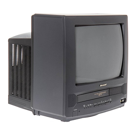
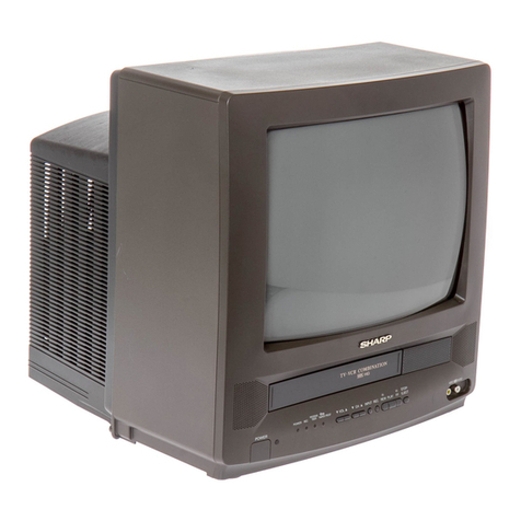
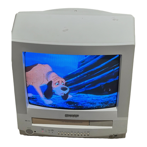
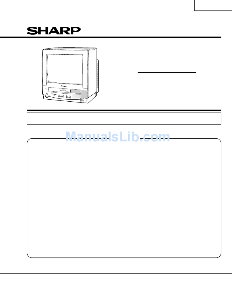
Sharp 37VT-26H User manual

1
37VT-26H(GY)
WARNING
Thechassisinthisreceiverispartiallyhot.Useanisolationtransformerbetweenthelinecordplugandpower
receptacle,whenservicingthischassis.Topreventelectricshock,donotremovecover.Nouser– serviceable
parts inside. Refer servicing to qualified service personnel.
SERVICE MANUAL
S99P337VT26H/
In the interests of user-safety (Required by safety regula-
tions in some countries) the set should be restored to its
originalcondition and onlyparts identical tothose specified
be used.
MODEL
SERVICE MANUAL TV/VCR COMBINATION TELEVIDEO MODEL 37VT-26H(GY)
SHARP CORPORATION
37VT-26H(GY)
TV/VCR COMBINATION
TELEVIDEO
Chassis No.VP-8
37VT-26H(GY)
FEATURE
ËAIS (Automatic Instruction System)
ËASS (Automatic Sorting System)
ËVPS/PDC (Video Program System / Program Delivery
Control)
ËFASTEXT
ËVIDEO Plus+
ËPost Cord Security
ËOn Screen Digital Channel/Sound Level/Tuning Display,
Control (Contrast, Colour, Brightness, Tint, Sharpness,
White temp) Symbol and Level
ËBlue Back OffTimer
Ë52 Key, Wireless Remote Control Unit
ËChannel Skip
ËHigh Speed and Double Speed Video Search System
»PAL : 3 times/7 times (SP/LP)
»NTSC : 3 times/5 times (SP/LP)
5 times/15 times (EP)
ËDPSS (Digital Program Search System)
ËQuick Start Playback with Full Loading System
ËDigital Automatic Tracking Control
ËAutomatic Playback Function
ËAHC (Automatic Head Cleaning System)
ËSharp Super Picture
Ë345 Times Hi-Speed FF/REW
CONTENTS Page
»SPECIFICATIONS ................................................................................................................................................................................. 2
»IMPORTANT SERVICE NOTES ............................................................................................................................................................ 3
»LOCATION OF USER'S CONTROL...................................................................................................................................................... 4
»DISASSEMBLY AND REASSEMBLY .................................................................................................................................................... 6
»ADJUSTMENT OF THE TV ELECTRICAL CIRCUITRY ........................................................................................................................9
»PRECAUTIONS IN REASSEMBLING ................................................................................................................................................ 19
»FUNCTION OF MAJOR MECHANICAL PARTS ................................................................................................................................. 20
»ADJUSTMENT, REPLACEMENT AND ASSEMBLY OF MECHANICAL UNITS ................................................................................. 22
»ADJUSTMENT OF THE VCR ELECTRICAL CIRCUITRY ...................................................................................................................41
»MECHANISM OPERATION FLOWCHART AND TROUBLESHOOTING GUIDE ............................................................................... 44
»CHASSIS LAYOUT .............................................................................................................................................................................. 63
»BLOCK DIAGRAM OFTV SECTION .................................................................................................................................................. 64
»BLOCK DIAGRAM OFVCR SECTION ............................................................................................................................................... 66
»DESCRIPTION OF SCHEMATIC DIAGRAM ...................................................................................................................................... 75
»SOLID STATE DEVICE BASE DIAGRAM ........................................................................................................................................... 76
»WAVEFORMS .....................................................................................................................................................................................77
»SCHEMATIC DIAGRAM ...................................................................................................................................................................... 78
»PRINTED WIRING BOARD ASSEMBLIES......................................................................................................................................... 92
»REPLACEMENT PARTS LIST ............................................................................................................................................................ 99
»PACKING OF THE SET ..................................................................................................................................................................... 115

37VT-26H(GY)
2
SPECIFICATIONS
ËOUTLINE OFTHE PRODUCT
Power Source: 220~240 V AC, 50 Hz
Power Consumption: 77 W
Receiving Broadcast Standard: I
Receiving Channel: VHF; 1A~S36
UHF; S37~C57
Receiving System: Sound; 6.0 MHz
Colour; PAL
Antenna Input Impedance: VHF/UHF; 75 ohm Unbalanced (DIN)
Video Signal: Input; 0.5-2.0 Vp-p/75 ohm (SCART/RCA)
Output; 1.0 Vp-p/75 ohm (SCART)
Audio Signal: Input; 0.5 Vrms/10k ohm (SCART/RCA)
Output; 0.5 Vrms/1k ohm (SCART) (54% MOD)
Temperature: Operation; 5°C to 40°C
Storage; -10°C to 60°C
Dimensions (Approx.): 378 mm (W) ×387 mm (H) ×384 mm (D)
Weight (Approx.): 12.7 kg
Cabinet Material: Plastic
Accessories: Operation Manual
Infrared Remote Control Unit
Dry Batteries, Type AA (×2 pcs.)
ËTV SECTION
Viewing Area: 33.54 cm Diagonal Measurement
Picture Power: 22.0 kV at 800 µA Beam Current
Speaker Output: 3.0 W at Max.(5×9 cm oval type ×1pc.)
Picture Tube: Type; VB370BVBK1S-S (Tint Tube)
Heater; 6.3 V, 300 mA
Focus; High Bi-Potential Electrostatic
ËVCR SECTION
Outline: VHS Video System ColourVideo Cassette Recorder
Format: VHS PAL/NTSC Standard
Video Recording System: Rotary Slant Azimuth 2-Head Helical Scan System
Luminance: FM Recording
Chrominance: Low Frequency Converted Direct Recording
Video Signal System: PAL/NTSC 3.58MHz Colour
Cassette Tape: VHS Type Video Cassette Tape
Tape Width: 12.7 mm
Tape Speed: PAL ; 23.39 mm/s (SP), 11.70 mm/s (LP)
NTSC ; 33.35 mm/s (SP), 16.68 mm/s (LP·PB only), 11.12 mm/s (EP)
Recording/Playback Time: SP ; Max. 240 min (with E-240)
LP ; Max. 480 min (with E-240, PAL only)
EP ; Max. 480 min (with T-160, NTSC only)
Number of Video Head: 4 pcs.
Note: The antenna must correspond to the new standard DIN 45325 (IEC 169-2) for combined UHF antenna with
75 ohm connector.
Specifications are subject to change without prior notice.

3
37VT-26H(GY)
IMPORTANT SERVICE NOTES
Maintenance and repair of this receiver should be done by qualified service
personnel only.
SERVICING OF HIGHVOLTAGE SYSTEM AND PIC-
TURETUBE
When servicing the high voltage system,remove static charge from it by con-
necting a 10k ohm Resistor in series with an insulated wire (such as a test
probe) between picture tube dag and 2nd anode lead.(AC line cord should be
disconnected from AC outlet.)
1. Picture tube in this receiver employs integral implosion protection.
2. Replace with tube of the same type number for continued safety.
3. Do not lift picture tube by the neck.
4. Handle the picture tube only when wearing shatterproof goggles and after discharging
the high voltage completely.
X-RAY
This receiver is designed so that any X-Ray radiation is kept to an absolute
minimum. Since certain malfunctions or servicing may produce potentially
hazardous radiation with prolonged exposure at close range, the following
precautions should be observed:
1. When repairing the circuit, be sure not to increase the high voltage to more than 25.3 kV,
(at beam 0 µA) for the set.
2. To keep the set in a normal operation,be sure to make it function on 22.0 kV + 1.5 kV – 2.0
kV (at beam 800 µA) in the case of the set. The set has been factory – Adjusted to the
above-mentioned high voltage.
∴ If there is a possibility that the high voltage fluctuates as a result of the repairs, never
forget to check for such high voltage after the work.
3. Do not substitute a picture tube with unauthorized types and/or brands which may cause
excess X-ray radiation.
BEFORE RETURNINGTHE RECEIVER
Before returning the receiver to the user,perform the following safety checks.
1. Inspect all lead dress to make certain that leads are not pinched or that hardware is not
lodged between the chassis and other metal parts in the receiver.
2. Inspect all protective devices such as non-metallic control knobs, insulating fishpapers,
cabinet backs, adjustment and compartment covers or shields, isolation resistor-capac-
ity networks, mechanical insulators etc.

37VT-26H(GY)
4
LOCATION OF USER'S CONTROL

5
37VT-26H(GY)
LOCATION OF USER'S CONTROL (CONTINUED)

37VT-26H(GY)
6
1. Remove the 11 rear cover fixing screws and detach the rear cover.
2. Take out the anode cap, CRT PWB, connectors H, G and F, coating ground, SP chip, fixing screws and others.
3. Remove the Main PWB fixing screws and take out the Main PWB unit and the Power PWB.
4. Remove the 4 Power PWB fixing screws, and take out the Power PWB unit.
DISASSEMBLY AND REASSEMBLY
G
F
H
3
2
4
1
1

7
37VT-26H(GY)
DISASSEMBLY AND REASSEMBLY (CONTINUED)
5. Remove the 8 VCR fixing screws, and detach the shielding case.
6. Remove the 4 cassette housing control fixing screws, and detach the cassette housing control.
7. Remove the 7 mechanism chassis fixing screws, and detach the mechanism chassis from the Main PWB.
8. Remove the 3 Main PWB fixing screws, and detach the Main PWB.
9. Remove the 2 Tuner/Def and IF PWB fixing screws, and detach the Tuner/Def and IF PWB.
5
6
7
7
7
7
8
9

37VT-26H(GY)
8
For servicing any of the components inside, disconnect the lead dressing holder. Position the main PWB unit upright
as shown below and connect the leads for starting the services.
DISASSEMBLY AND REASSEMBLY (CONTINUED)
AO
AJ
H
PC
PC
K
AV
A
A
F
G
S
AJ
S
K
F
H
AV
PA
PB
PB
PA
AB
G
AB
70~80°
Note: Fit the VCR unit the front cabinet with the front flap door tilted at 70~80°.

9
37VT-26H(GY)
ADJUSTMENT OFTHETV ELECTRICAL CIRCUITRY
ADJUSTMENT PRECAUTIONS
1. Calling the service mode
Get the service test points (TP2002 and TP2003) of the set short-circuited.
2. Getting out of the service mode
Get the above service test points open.
3. On-screen display in the service mode
A service mode item and its data appear in two lines
at the lower left on the screen.
Service mode
Item Display Data Variable range
DIRECT MODE →Adjustable in the DIRECT MODE
V-AMPLITUDE V-AMP 0 ~ 127 R CUT OFF (0 ~ 255)
V-LINEARITY V-LIN 0 ~ 31 G CUT OFF (0 ~ 255)
V-OUT PHASE V-POS 0 ~ 7 B CUT OFF (0 ~ 255)
H-POSITION H-POS 0 ~ 31 G DRIVE GAIN (0 ~ 255)
BELL FILTER BELL 0 ~ 3 B DRIVE GAIN (0 ~ 255)
R-Y BLACK OFFSET R-Y 0 ~ 15
B-Y BLACK OFFSET B-Y 0 ~ 15
Y-SUB CONTRAST CONT 0 ~ 31
SUB COLOUR COLOR 0 ~ 240
SUB BRIGHT BRI 0 ~ 150
SUB TINT TINT 0 ~ 37
Top line : Service mode item (See below)
Micon version display
Bottom line : Data (See below)
Note :
Item selectable by the CH '" keys and data by the VOL '" keys (effective on both the
remote controller and the set)
The numeric keys on the remote controller work as follows in the DIRECT mode only.
UP DOWN
R CUT OFF 1 4
G CUT OFF 2 5
B CUT OFF 3 6
G DRIVE GAIN 7
õ
Õ
B DRIVE GAIN 8 0
Notes :
In all the other modes, these keys are used to select channels.
In the DIRECTTUNING mode, these keys are used to enter data.

37VT-26H(GY)
10
Item-by-item control in the service mode
1. DIRECT mode F-B/W 0 - > 1 (forced B/W)
2. DIRECT mode + HOR. POS. mode DRV CNT 0 - > 1 (drive forced center)
SUB-BRIGHT Initial value
R.G.B. CUTOFF 0 (E2PROM data resumed when any of the “0” thru
“9” keys on the remote controller is pressed)
3. R-Y Black Offset CONTRAST MAX (USER-CONTROL)
BRIGHT MAX (USER-CONTROL)
COLOUR CENTER (USER-CONTROL)
R-MONITOR SW 0 - > 1 (MONITOR OUT)
MUTE MODE Y-MUTE
4. B-Y Black Offset CONTRAST MAX (USER-CONTROL)
BRIGHT MAX (USER-CONTROL)
COLOUR CENTER (USER-CONTROL)
B-MONITOR SW 0 - > 1 (MONITOR OUT)
MUTE MODE Y-MUTE
5. SUB Tint MUTE MODE Y-MUTE
6. Unspecified items PICTURE NORMAL (CONT. BRI. COL.)
Note :
All the settings will be back to the initial ones when shifting into any other mode or getting out of the
service mode.
Allocation of special keys in the service mode
`HORIZONTAL POSITION key CONFIRM (SET -> S-PICTURE)
`Y-MUTE KEY SET
`COLOUR MAX./MIN. select key TIMER ON/OFF
`DIRECT TUNING MODE KEY RETURN
`VCR SLOWTEST KEY PROG
`NVM MODE KEY DISPLAY
Adjustment precautions
1) Basically follow the sequential order of adjustments.
(Unless otherwise specified, follow the adjustment procedures.)
2) The “`”-marked steps in the adjustment procedures are automatically taken when in the service mode. Leave
out these steps.
3) For adjustments in the service mode, it is necessary to have the remote controller at hand.
Trouble indicators
If the set is interrupted by the protectors, the following indicators work to identify a spot in trouble.
1) LED (red) flashing : Deflection system protector activated (high-voltage or beam vert, out protector)
2) REC LED flashing : IIC bus line error (VCJ or tuner, EEPROM, TEXT, PDC)
3) LED off : Power protector activated (+B line short-circuited)

11
37VT-26H(GY)
Initial settings of EEPROM data
Initial settings of adjustment items
Item Variable range Initial setting
R CUT OFF 0 ~ 255 0
G CUT OFF 0 ~ 255 0
B CUT OFF 0 ~ 255 0
V-AMPLITUDE 50Hz 0 ~ 127 35
V-AMPLITUDE 60Hz 0 ~ 127 37
V-LINEARITY 50Hz 0 ~ 31 25
V-LINEARITY 60Hz 0 ~ 31 18
V-OUT PHASE 50Hz 0 ~ 7 05
V-OUT PHASE 60Hz 0 ~ 7 02
HORIZONTAL POSITION 50Hz 0 ~ 31 05
HORIZONTAL POSITION 60HZ 0 ~ 31 09
Y-SUB CONTRAST 0 ~ 31 0
SUB-COLOUR 0 ~ 240 91
SUB-BRIGHT 0 ~ 150 100
G-DRIVE GAIN 0 ~ 255 128
B-DRIVE GAIN 0 ~ 255 128
SUB-TINT 0 ~ 37 20
BELL FO 0 ~ 3 01
R-Y BLACK OFFSET 0 ~ 15 8
B-Y BLACK OFFSET 0 ~ 15 8
PICTURE Adjust User setting
Initial setting : NORMAL (CONTRAST at 52, others at CENTER)

37VT-26H(GY)
12
ËË
ËË
ËPURITY ADJUSTMENT
1. PURITY ADJUSTMENT
1. First of all, let a beam current of over 400µA flow
in the set to warm it up for 30 minutes or longer.
2. Keep the purity magnet in the zero magnetic field
in advance. Roughly adjust the static conver-
gence.
3. Receive the green-only colour signal. Adjust the
beam current to about 500 µA.
4. Degauss the cathode ray tube enough with the
degaussing coil.
ADJUSTMENT
Eastward magnetic field specified
1) Observe the beam landings “a” and “b”, as
shown in
Fig. A
, through a microscope. Ad-
just the landings as specified.(
Fig. B
,
Fig. C
)
2) If the right and left landings are equally out-
ward, move the deflection yoke forward.
3) If the right or left landing is shifted to the right
or to the left, adjust the opening angle of the
purity magnet.
4) Makesure therightandleft beam landingsare
just as specified about the screen center.Now
check the cathode ray tube corners.
Be sure that all the landings are at rank “B”.
5) If any other colour appears on the screen,
move the deflection yoke back and forth.
LANDING ERROR
»Outward:Move the deflection yoke forward.
»Inward:Move the deflection yoke backward.
6) Receive the monoscope pattern signal.
RASTER ROTATION
7) Adjust the raster rotation to “0” eastward.
»Adjustment error : 0 ±2 mm
8) Tighten up the deflection coil screws.
»Tightening torque : 11±2 kg
Note : Each time the single-colour keyis pressed,
the screen colour changes as follows.
Fig. A
Green-only
screen Red-only
screen
Single-colour
screen cleared
Blue-only
screen
ab
A=B
AB
A=B
AB
Fig. B
Fig. C

13
37VT-26H(GY)
ËË
ËË
ËCONVERGENCE ADJUSTMENT
1. CONVERGENCE ADJUSTMENT
(to be done after the purity adjustment)
Wedge "a"
Lacqure
Wedge "b" Wedge "c"
Approx.100°Approx.100°
4-pole magnet
6-pole magnet
CRT neck
Lacquer
Purity magnet
1. Receive the crosshatch pattern signal.
2. Usingthe remote controller, call theNormalmode.
STATIC CONVERGENCE
1. Turn the 4-pole magnet to a proper opening an-
gle in order to superimpose the blue and red col-
ours.
2. Turn the 6-pole magnet to a proper opening an-
gle in order to superimpose the green colour over
the blue and red colours.
DYNAMIC CONVERGENCE
1. Adjust the convergence on the fringes of the
screen in the following steps.
»Fig. a :Drive the wedge at point “a” and
swing the deflection coil upward.
»Fig. b :Drive the wedges at points “b” and
“c” and swing the deflection coil
downward.
»Fig. c :Drive the “c” wedge deeper and
swing the deflection coil rightward.
»Fig. d :Drive the “d” wedge deeper and
swing the deflection coil leftward.
2. Fix all the wedges on the cathode ray tube and
apply glass tape over them.
3. Apply lacquer to the deflection yoke lock screw,
magnet unit (purity, 4-pole and 6-pole magnets),
and magnet unit lock screw.
Finally receive the red-only and blue-only colour sig-
nals and make sure there is no other colour mixed
on the screen.
B G R
B
G
R
R G B B
G
R
R G B
R
G
B
B G R R
G
B
Fig. a Fig. b
Fig. c Fig. d
Fig. 1

37VT-26H(GY)
14
ËË
ËË
ËCRT CUT-OFF, BACKGROUND AND SUB-CONTRAST ADJUSTMENT (1)
1. CRT CUT-OFF (I2C bus data adjustment)
1. Receive the monoscope pattern signal.
2. Put the set in the service mode and call up the DIRECT mode (DIRCT).
3. Set the screen control to 0/10 position.
4. Press the“CONFIRM”key on the remote controller to reach the horizontal centering mode.(S-PICTURE key on
the set)
5. Turn the screen control clockwise until the horizontal raster of the first glimmering colour becomes slightly
visible.
6. Adjust the cut-off data of the other two colours until the horizontal raster becomes whitish.
Note : The data can be turned up and down with the above keys.
»R CUT OFF UP “1” KEY »G CUT OFF DOWN “5” KEY
»R CUT OFF DOWN “4” KEY »B CUT OFF UP “3” KEY
»G CUT OFF UP “2” KEY »B CUT OFF DOWN “6” KEY
7. Turn the screen control counterclockwise until the horizontal raster disappears.
Note : Before starting this adjustment,warm up the unit for 30 minutes or longer at a beam current of over
600 µA.
8. Press the “CONFIRM”key on the remote controller to call up the NORMAL mode.(S-PICTURE key on the set)
SUB-BRIGHTNESS (I2C bus data adjustment)
9. Using the remote controller, call the SUB-BRIGHT setting mode (BRI).(Receive the crosshatch and gray scale
signal.)
10.Set the sub-brightness data so that the third black portion (1st to 5th counted from the left of the screen) of the
window pattern looks sinking.
Note : The service mode adjustment in the above steps 9. and 10. should be carried out after the white
balance and background adjustments.
11.Exit from the service mode.
2. WHITE BALANCE AND BACKGROUND (I2C bus data adjustment)
1. Receive the monoscope pattern signal.
2. Put the set in the service mode and call up the DIRECT mode (DIRCT).
3. Connect the beam ammeter between TP601 and TP602.
4. Using the sub-contrast control, roughly adjust the beam current to about 700 µA.
5. Adjust the G-drive and B-drive data to have a colour temperature of 9,000°K (white).
»9,000°K x : 0.290
y : 0.284
(with a Minolta colour temperature meter CA-100)
Note : The data can be turned up and down with the above keys.
»G-DRIVE UP “7” KEY »B-DRIVE UP “8” KEY
»G-DRIVE DOWN “
õ
Õ
” KEY »B-DRIVE DOWN “0” KEY
6. Adjust the contrast and brightness controls to have the beam current of 200 µA or so. Now check the back-
ground colour. If the colour temperature is not as specified, go back to No. 1 on the preceding page.
7. Exit from the service mode.
Note : Before starting this adjustment,warm up the unit for 30 minutes or longer at a beam current of over
600 µA.

15
37VT-26H(GY)
3. SUB-CONTRAST
(I2C bus data adjustment)
1. Receive the crosshatch pattern signal.
2. Put the set in the service mode and select the SUB-CONTRAST mode (CONT).
3. Adjust the sub-contrast data to "0".
4. Exit from the service mode.
Note :
The selected channels in parentheses have the
following signals.
Monoscope pattern (50 Hz) signal
Fig.2
AB
ËË
ËË
ËHORIZONTAL AND VERTICAL CIRCUIT ADJUSTMENT
1. SERVICE MODE DATA ADJUSTMENT
Put the set in the service mode.
Turn up or down the data for this adjustment.
I2C bus data adjustment
»V-AMP 50 Hz
A) Select the V-AMP mode (V-AMP). Adjust the
overscan to 9% .
»V-LINEARITY - 50 Hz
B) Select the V-LIN mode (V-LIN). Adjust to get the
best linearity.
»V-OUT PHASE - 50 Hz (V-CENTER)
C) Select the V-OUT POS mode (V-POS). Align the
screen center with the cathode ray tube’s geo-
metrical center.
»H-POS 50 Hz (H-CENTER)
D) Select the H-POS mode (H-POS). Make the dis-
tances “A” and “B” on both sides equal.
Exit from the service mode.
Adjust point
Fig.3
2. FOCUS ADJUSTMENT
1. Receive the monoscope pattern signal.
2. Makethe PICTUREADJUSTsettingtoNORMAL.
3. Adjust the focus control so that the middle areas
betweenthepattern’s center and the screen’sboth
ends be in the best focus.
For theV-AMP 60 Hz, V-LINEARITY 60 Hz,V-OUT PHASE 60 Hz, and H-POS 60 Hz adjustments, their corrected
data are automatically entered when the corresponding 50-Hz mode adjustments are made.Check these data on
the 60 Hz mode screen. Readjust any of them if required. (The 50 Hz and 60 Hz modes are selected on the
screen.)
Once the adjustment has been made in the 60 Hz mode, do not change it in the 50 Hz mode.
ËË
ËË
ËCRT CUT-OFF, BACKGROUND AND SUB-CONTRAST ADJUSTMENT (2)

37VT-26H(GY)
16
ËË
ËË
ËPAL CHROMA ADJUSTMENT
1. SUB-COLOUR ADJUSTMENT (I2C bus data adjustment)
1. Receive the PAL colour bar signal.
2. Put the set in the service mode.
3. Select the sub-colour mode (COL).
4. Connect the oscilloscope to TP1852 (RED cath-
ode). (Use a 10 : 1 probe.)
»Range: 20 V/div.
»Sweep time: 20 µsec/div.
5. Adjust the sub-colour data so that the 75% white
and red portions of the PAL colour bar be at the
same level. See
Fig. 4
.
6. Exit from the service mode.
»When getting out of the SUB-COLOUR mode,
the sub-colour data turns up 15.
WYCYG
MG
RB
To be at the same level
WY
CY
G
MG
RB
About 3 Vp-p
ËË
ËË
ËNTSC CHROMA ADJUSTMENT
1. SUB-TINT ADJUSTMENT (I2C bus data adjustment)
1. Receive the NTSC colour bar signal.
2. Put the set in the service mode.
3. Select the SUB-TINT mode (TINT).
4. Connect the oscilloscope to TP802 (B-Y OUT).
»Range : 10 mV/div. (AC)
»Sweep time :10 µsec/div.
(Use a 10 : 1 probe.)
5. Adjust the sub-tint data to obtain the waveform as
shown in
Fig. 5
.
6. Exit from the service mode.
Fig.5
Fig.4
ËË
ËË
ËA/V INPUT AND OUTPUT CHECK (1)
1.VIDEO and AUDIO OUTPUT CHECK
1. Receive the E-69CH.
(100% white colour bar, 400 Hz, 100% modulation audio)
2. Terminate the video output with a 75Ωimpedance.Make sure the out-
put is as specified
(1.0 Vp-p ±3 dB(0.71 – 1.41 Vp-p).
3. Terminate the audio output with a 10k ohm impedance.Make sure the
output is as specified (2.6 Vp-p ±3 dB(1.84 – 3.67 Vp-p).
»Makesure thevideoand audio signalsfromthe tuner areoutputted.
WAVEFORM & OTHER
21PIN SCART
VIDEO OUT 19 PIN
AUDIO OUT 1, 3 PIN
SC401(REAR)........AV1
1. Receive the E-69CH.
2. Feed the video and audio signal via the A/V input jacks.
3. Using the CH '/"keys on the remote controller, change to the AV
mode and make sure the external video and audio outputs are accord-
ingly given.
(The AV mode can be picked up between 1CH and 0CH.)
CH '99 →0 →AV1 →AV2 →1 →2
CH "2 →1 →AV2 →AV1 →0 →99
»The AV mode may also be picked up using the TV/VIDEO key on
the remote controller.
RF →AV1 →AV2 →RF
WAVEFORM & OTHER
SC401(REAR)........AV1
J1401(FRONT).......AV2
2. VIDEO and AUDIO INPUT CHECK

17
37VT-26H(GY)
ËË
ËË
ËA/V INPUT AND OUTPUT CHECK (2)
21PIN Euro-SCART (REAR)
1. BEAM PROTECTOR
1. Receive the monoscope pattern signal.
2. Set the contrast control to maximum.
3. Set the brightness control to maximum.
4. Make a short-circuit between the collector and emitter of Q1801 and
make sure that the protector is activated and the stand-by mode is
called. (The POWER LED indicator starts flashing in red.)
2. HIGH-VOLTAGE PROTECTOR
1. Receive the monoscope pattern signal.
2. Connect the bias box to TP603.
3. Adjust the bias box voltage to 20V and make sure that the protector is
not activated.
Note : Normally about 19 V
4. Adjust the bias box voltage to 25V and make sure that the protector is
activated.
3. OTHER PROTECTORS
»In checking the performance of other protectors — for example, the
one against shorting of smoothing electrolytic capacitor of +B line —,
pay attention not to damage or deteriorate any related element.
121 35791113151719
2468101214161820
1. Audio right output
2. Audio right input
3. Audio left output
4. Commom earth for audio
5. Earth for blue
6. Audio left input
7. Blue input
15. Red input
16. Red/Green/Blue control
17. Earth for video
18. Earth for Red/Green/Blue control
19. Video output
20. Video input
21. Plug shield
8. Audio-video control
9. Earth for green
10. Not used
11. Green input
12. Not used
13. Earth for red
14. Not used
ËË
ËË
ËPROTECTOR PERFORMANCE CHECK
Fig.6
1. CONTRAST KEY
1. Receive the mono scope pattern signal.
2. UsingthePICTUREADJUSTcontrol,selectCON-
TRAST.
3. Thecontrastmust be changeablewith the +/-key.
2. COLOUR KEY
1. Receive the PAL colour bar signal.
2. Usingthe PICTURE ADJUST control, select COL-
OUR.
3. The colour must be changeable with the +/- key.
(There must be no colour at the MIN position.)
3. BRIGHTNESS KEY
1. Receive the monoscope pattern signal.
2. Using the PICTURE ADJUST control, select
BRIGHT.
3. The black level must be changeable with the +/-
key.
R/C MENU KEY
→PICTURE ADJUST
→CONTRAST
→COLOUR
→BRIGHT
→TINT
→V-TONE
→WHITE TEMP
→NORMAL
ËË
ËË
ËFUNCTION CHECK (1) (VIDEO AND AUDIO)

37VT-26H(GY)
18
ËË
ËË
ËFUNCTION CHECK (2) (VIDEO AND AUDIO)
4.TINT KEY
1. Receive the NTSC colour bar signal. (AV2 input)
2. Using the PICTURE ADJUST control, select TINT.
3. The tint must be changeable toward green with the + key and toward red with the - key.
5. PIC-NORMAL KEY
1. With the PICTURE ADJUST control, select NORMAL. Make sure the following normal settings are displayed.
Here are the normal settings.
»Contrast : 52
»Colour : CENTER (0)
»Brightness : CENTER (0)
»Tint : CENTER (0)
»Sharpness : CENTER (0)
»White Temp : CENTER (0)
6.WHITETEMP KEY
1. Receive the monoscope pattern signal.
2. Using the PICTURE ADJUST control, select WHITE TEMP.
3. The BACK GND must be changeable with the +/- key with the + key (The warm direction with the + key, the cold
direction with the - key ).
7.V-TONE KEY
1. Receive the monoscope pattern signal.
2. Using the PICTURE ADJUST control, select V-TONE.
3. The sharpness must be changeable with the +/- key.
8. CHANNEL SIGH DISPLAY COLOUR
1. The display colour of all the channel (0 ~ 99) signs must be green (AFT on).
9. COLOUR SYSTEM KEY
1. Input PAL COLOUR BAR with AV 1, 2. Using the
COLOURSYSTEM key, select amodeother than
AUTO/PALandmakesure thecoloursystemdoes
not work properly.
2. When receive the E-69CH. PAL COLOUR BAR,
make sure the colour system work properly.
3. When receive the JA-8CH NTSC 3.58 COLOUR
BAR, make sure the colour system does not work
properly.
R/C MENU KEY
→COLOUR SYSTEM
(Selection is possible only at the time of the AV mode.)

19
37VT-26H(GY)
PRECAUTIONS IN REASSEMBLING
Pulley feed gear
Screwdriver
Tilt mark (*1)
Casecon
drive gear
Drive angle of
cassette control
INSTALLING THE CASSETTE CONTROLLER
When the cassette controller is installed on the mecha-
nism, the initial setting is essential condition.
There are two initial setting methods, namely electrical
and mechanical.
1. Electrical initial setting
Makea short-circuit betweenTP7701and TP7702 then
plug in the AC cord and be sure that the mechanism is
back to its initial setting position (*1). Now install the
cassettecontrollerinposition.(Conditions:Whenmecha-
nism and PWB have been installed)
INSTALLING THE MECHANISM ON PWB
Lower vertically the mechanism, paying attention to the
mechanism edge, and install the mechanism with due
care so that the parts are not damaged. So as to fix the
mechanismtothemainPWBtightenupthetwoscrews.
(One for fixing the mechanism and the head amplifier
shield, the other on the main PWB's soldering side and
locatedneartheloadingmotor.)ConnectagaintheFFC
cable (AA-MH, AD-ME, AH-MZ) between the mecha-
nism and the main PWB.
PARTS WHICH NEED PARTICULAR CARE
When installing the mechanism chassis on the PWB
unit, take care so as to prevent deformation due to
contact of mechanism chassis with Rec tip switch
(S7701),Startsensor(Q7703)andEndsensor(Q7704).
2. Mechanical initial setting
Feed the pulley feed gear of loading motor with screw
driver. After ascertaining the return to the initial set
position (*1) install the cassette controller in the speci-
fiedposition.(Thismethodisappliedonlyforthemecha-
nism.)
END SENSOR
REC TIP SW
AE CONNECTOR
AL CONNECTOR START SENSOR
AC CONNECTOR

37VT-26H(GY)
20
No. Function No. Function
1 Full erase head
2 Supply pole base ass'y
3 Tension arm ass'y
4 Idler wheel ass’y
5 Pinch drive lever ass’y
6 Supply reel disk
7 Supply main brake ass'y
8 Take-up main brake ass'y
9 Pinch drive cam
10 A/C Head ass’y
11 Reverse guide lever ass'y
12 Casecon drive gear
13 Take-up reel disk
14 Pinch roller lever ass’y
15 Drum ass'y
16 Loading motor
17 Drum motor
18 Take-up pole base ass'y
27 Fixing guide
1715 10 27
11
5
9
14
12
8
16
13
4
6
2
7
3
1
18
FUNCTION OF MAJOR MECHANICAL PARTS (TOP VIEW)
This manual suits for next models
1
Table of contents
Other Sharp TV VCR Combo manuals

Sharp
Sharp 13VT-R100 User manual

Sharp
Sharp VT-3448X User manual

Sharp
Sharp 13VT-R100 User manual

Sharp
Sharp VT-G14 User manual

Sharp
Sharp 13VT-N100 User manual

Sharp
Sharp 25VT-J100 User manual

Sharp
Sharp 13VT-CR10 User manual

Sharp
Sharp 25VT-K100 User manual

Sharp
Sharp 13VT-N200 User manual

Sharp
Sharp VT-3418X User manual