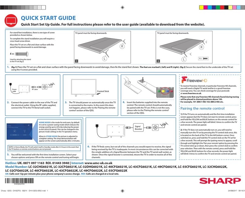
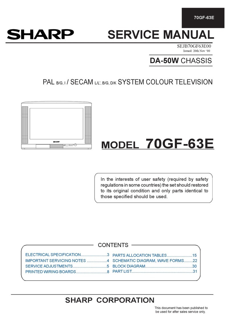
Sharp 20MR10 User manual

1
20MR10
COLOR TELEVISION
Chassis No. SN-010
In the interests of user-safety (Required by safety regulationsin some countries)the set shouldbe restoredto its
original
condition
and only parts
identical
to those specified
should
be used.
ELECTRICAL SPECIFICA TIONS ......................................................................................................... 1
IMPORTANT SER VICE SAFETY PRECAUTION ................................................................................. 2
LOCATION OF USER'S CONTROL ..................................................................................................... 4
INSTALLATION AND SER VICE INSTRUCTIONS ................................................................................ 5
CHASSIS LAYOUT ............................................................................................................................. 11
BLOCK DIAGRAM .............................................................................................................................. 12
SCHEMATIC DIAGRAMS ................................................................................................................... 13
PRINTED WIRING BOARD ASSEMBLIES ........................................................................................ 20
REPLACEMENT PARTS LIST ............................................................................................................23
PACKING OF THE SET ............................................................................................................. ......... 29
Page
SHARP CORPORA TION This documenthas been publishedto be used for after
sales service only.
The
contents
are
subject
to
change
without
notice.
CONTENTS
SER VICE MANUAL
POWER INPUT .................................................... AC 120 V, 60 Hz
POWER RATING ................................................................... 69 W
PICTURE SIZE ........................................... 1,194cm2(185sq inch)
CONVERGENCE ............................................................. Magnetic
SWEEP DEFLECTION .................................................... Magnetic
FOCUS ............................................... Hi-Bi-Potential Electrostatic
INTERMEDIATE FREQUENCIES
Picture IF Carrier Frequency..................................... 45.75 MHz
Sound IF Carrier Frequency...................................... 41.25 MHz
Color Sub-Carrier Frequency .................................... 42.17 MHz
(Nominal)
AUDIO POWER
OUTPUT RATING ..................................................... 1 W (RMS)
ELECTRICAL SPECIFICA TIONS
SPEAKER
SIZE ...................................................................... 8 cm (Round)
VOICE COIL IMPEDANCE ............................ 32 ohm at 400 Hz
ANTENNA INPUT IMPEDANCE
VHF/UHF ..................................................... 75 ohm Unbalanced
TUNING RANGES
VHF-Channels ............................................................... 2 thru 13
UHF-Channels ............................................................ 14 thru 69
CATV Channels ........................................................... 1 thru 125
(EIA, Channel Plan U.S.A.)
Specifications are subject to change without
prior notice.
MODEL 20MR10
S11O220MR10
PO
W
ERV
O
LCHV
ID
EOA
U
D
IO
IN
M
EN
U

2
20MR10
IMPORTANT SERVICE SAFETY PRECAUTION
Service workshould be performed only by qualified service technicians who are thoroughly
familiar withall safety checks and the servicing guidelines which follow:
4A 125V
SER VICING OF HIGH VOLTAGE SYSTEM
AND PICTURE TUBE
When servicing the high voltage system,
remove the static charge by connecting a
10k ohm resistor in series withan insulated
wire (such as a test probe) between the pic-
ture tube ground and the anode lead. (AC
line cord should be disconnected from AC
outlet.)
1. Picture tube in this receiver employs integral
implosion protection.
2.Replace with tube of the same type number for
continued safety.
3. Do not lift
picture
tube
by the neck.
4.Handle the picture tube only when
wearing
shatterproof goggles and after discharging
the
high voltage anode completely.
X-RADIATION AND HIGH VOLTAGE LIMITS
1. Be sure all service personnel are aware of
the
procedures and instructions covering X-radiation.
The only potential source of X-ray in current solid
state TV receivers is the
picture
tube. However, the
picture tube does not emit measurable
X-Ray
radiation, if the high voltage is as specified in
the
"High Voltage Check" instructions.
It is only when high voltage is excessive that X-
radiation is capable of penetrating the shell of the
picture
tube
including
the lead in the glass material.
The important
precaution
is to keep the
high
voltage below the maximum level specified.
2. It is essential that servicemen have available at all
times an accurate high voltage meter.
The calibration of this meter should be checked
periodically.
3.High
voltage should alwaysbe
kept
at the
rated
value
-no higher. Operationat higher voltages may
cause
a failure of the picture tube or high voltage circuitry
and; also,
under
certain conditions, may produce
radiation in exceeding of desirable levels.
4.Whenthe high voltage regulator is operating properly
there is no possibility of an X-radiation problem.
Every time acolorchassis is serviced,the brightness
should be tested while
monitoring
the high
voltage
witha meter to be certain that the high voltage
does
not
exceed
the
specified
value
and
that
it
is
regulating
correctly.
5. Do not use a picture tube other than that specified
or make
unrecommended
circuit
modifications
to
the
high voltage circuitry.
6.
When
troubles hooting
and taking test
measurements
on a
receiver
with
excessive
high
voltage,
avoid being unnecessarily close to the receiver.
Do
not
operate
the
receiver
longer
than
is
necessary
to locate the cause of
excessive
voltage.
WARNING
1. For continued safety, no
modification
of any circuit
should be attempted.
2. Disconnect AC powerbefore servicing.
3.Semiconductor heat sinks are
potential
shock
hazards when the chassis is operating.
4. The chassis in this
receiver
has two
ground
systems
whichare separatedby
insulating
material.
The
non-
isolated (hot) ground system is for the B+
voltage
regulator
circuit
and
the
horizontal
output
circuit.
The
isolated
ground
system
is for the low B+
DC
voltages
and the secondary
circuit
of
the
high
voltage
transformer.
Toprevent electrical shock use an
isolation
transformer between the line cord and power
receptacle, when servicing this chassis.
CAUTION: FOR CONTINUED
PROTECTION AGAINST A
RISK OF FIRE, REPLACE
ONLYWITH SAME TYPE 4A-
125V FUSE.

3
20MR10
SAFETY NOTICE
Many electrical and mechanical parts in television
recevers have special
safety-related
characteristics.
These
characteristics
are often not
evident
from visual
inspection, nor can protection afforded by them be
necessarily
increased
byusing
replacement
components
rated for higher voltage,
wattageand etc.
Replacement parts which have these special safety
characteristics are identified in this manual; electrical
components
havingsuch features are
identified
by " "
and shaded areas in the Replacement Parts Lists and
Schematic Diagrams.
IMPORTANT SER VICE SAFETY PRECAUTION
(Continued)
1. Inspect all lead dress to make certain that leads are
not pinchedor that hardwareis not lodgedbetween
the chassis and other metal parts in the receiver.
2. Inspect all protectivedevices such as non-metallic
control knobs, insulating materials, cabinet backs,
adjustment and compartment covers or shields,
isolation resistor-capacity networks, mechanical
insulatorsand etc.
3. To
be sure that no shock hazard exists, check for
leakage currentin the following manner.
Plug the AC cord directly into a 120 volt AC outlet,
(Do not use an isolation transformer for this test).
Using two clip leads, connect a 1.5k ohm, 10 watt
resistor paralleled by a 0.15µF capacitor in series
with all exposed metal cabinet parts and a known
earth ground,such as electrical conduitor electrical
ground connected to earth ground.
Use an AC voltmeter having with 5000 ohm per volt,
or higher, sensitivity to measure the AC voltage drop
across the resistor.
For continued protection, replacement parts must be
identical
to those used in the
original
circuit.The use of
substitute
replacement
parts
which
do not have
the
same
safety characteristics as the factory recommended
replacement
parts shown in this service manual, may
create shock, fire,
X-radiation
or other hazards.
BEFORE RETURNING THE RECEIVER
(Fire Shock Hazard)
Before returning the receiver to the user, perform
the following safety checks.
Connectthe resistorconnection to all
exposed
metal
parts having a returnto the chassis (antenna, metal
cabinet, screw heads, knobs and control shafts,
escutcheon and etc.) and measure the AC voltage
drop across the resistor.
AII checks must be repeated with the AC line cord
plug connection reversed. (If necessary, a non-
polarized adapter plug must be used only for the
purposeof
completing
these check.)
Any
current
measured
must
not
exceed
0.5 milliamp.
Any measurements not within the limits outlined
above indicate of a potential shock hazard and
corrective
action
mustbe taken before
returning
the
instrument to the customer.
1.5k ohm
10W
0.15 F
TEST PR OBE
CONNECT TO
KNOWN EARTH
GROUND
TO EXPOSED
METAL PARTS
&
!
4
20MR10
LOCATION OF USER'S CONTROL
TV
CH
–VOL +
POWER VIDEO IN AUDIO
CH
–VOL+
POWER
MENU
MENU
Infrared Transmitter Window
INPUT
Press Switch to external video input
mode.
Press again Switch to TV mode.
CHANNEL UP/DOWN
( ) Selects next higher channel.
( ) Selects next lower channel.
• Moves the “ ” mark of the MENU
screen.
MENU
Press Accesses MAIN MENU.
Press again Exits MAIN MENU.
DISPLAY
Press Displays receiving channel for
four seconds.
Press again Removes display.
• Temporarily displays receiving
channel when in Closed Caption
mode.
CHANNEL UP/DOWN
() Selects next higher channel.
( ) Selects next lower channel.
• Press both at the same time to
access the MAIN MENU screen.
VOLUME UP/DOWN
(+) Increases sound.
(–) Decreases sound.
POWER
Press On.
Press again Off.
REMOTE KEYPAD
Accesses any channel from keypad.
FLASHBACK
Returns to previous channel.
VOLUME UP/DOWN
(+) Increases sound.
(–) Decreases sound.
• In menu mode, changes or selects
the TV adjustments.
MUTE
Press Mutes sound.
Press again Restores sound.
• CLOSED CAPTION appears when
sound is muted.
POWER
Press
On.
Press again Off.
SENSOR AREA FOR
REMOTE CONTROL
VIDEO IN AUDIO IN TERMINALS
G1339SB
Basic Remote Control Functions
Front Panel

5
20MR10
CIRCUIT PROTECTION
The receiver is protected by a 4.0A fuse (F701),
mounted on PWB-A, wired into one side of the AC
line input.
X-RADIATION PROTECT OR CIRCUIT TEST
After service has been performed on the horizontal
deflection system, high voltage system, B+system,
test the X-Radiation protection circuit to ascertain
proper operation as follows:
1. Apply 120V AC using a variac
transformer
for
accurate input voltage.
2.
Allow
for warm up and adjust all customer
controls
for normalpicture and sound.
3. Receive a good local channel.
4. Connect a
digital
voltmeter
to TP653 and make sure
that the
voltmeter
reads 21.4 ±1.5V.
5.Apply external 27.2V DC at TP653 by
using
an
external DC supply, TV must be shut of f.
6. To
reset
the
protector
,
unplug
the AC cord
and
make
a
short
circuit
between
TP651
and
TP652.
Now
make
sure that
normal
picture
appears
on the screen.
7. If the
operation
of the
horizontal
oscillator
does
not
stop in step 5, the
circuit
must be
repaired
before
the set is
returned
to the customer.
HIGH VOLTAGE CHECK
High voltage is not adjustable but must be
checked
to verify that the receiver is operating within
safe
and efficient design limitations as specified checks
should be as follows:
1. Connect an accurate high voltage meter
between
ground
and
anode of
picture
tube.
2. Operate
receiver
for at least 15 minutes at 120V
AC
line voltage, with a strong air signal or a
properly
tuned in test signal.
3.Enter the service mode and select the
service
adjustment
"S03" and Bus data "01" (Y-mute on).
4.The
voltage
should
be
approximately
26.0kV (at zero
beam).
If a correct reading cannot be obtained, check
circuitry for
malfunctioning
components.
After the
voltage test, make
Y-mute of
f to the normal mode.
INSTALLATION AND SERVICE INSTRUCTIONS
Note: (1) When performing any adjustments to resistor controls and transformers use non-metallic
screwdrivers or TV alignment tools.
(2) Before performing adjustments, the TV set must be on at least 15 minutes.

6
20MR10
For adjustments of this model, the bus data is converted to various analog signals by the D/A
converter
circuit.
Note: There are still a few analog adjustments in this series such as focus and master screen voltage.
Follow
the steps below whenever the service adjusment is required.
To enter the service mode and exit service mode.
While
pressing
the Vol-up and Ch-up
buttons
at the
sametime,
plug
the AC cord into a wall socket.
Now, the TV set is
switched
on and enters the service mode.
To
exit
the service mode,
turn
the
television
off by
pressing
the
power
button.
1. Service mode.
Before
putting
unit
into
the service mode,
check
that
customer
adjustments
are in the
normal
mode.
Use the reset
function
in the
video
adjustment
menu
to ensure
customer
control
are in
their
proper
(reset) position.
2. Service number selection.
In the service mode, you will see the
window
screen as window . There are 3 adjustment categories DEF,
SIGNAL, FIX VALUE as show in Figure A.
Press CH UP/DOWN buttonfor selectionand enter by VOL UP or VOL DOWN.
Press CH UP/DOWN
button
to
select
the
adjustment
item and VOL UP/DOWN
to adjust the data
number
for each categories.
(OSD disturbance can be erased by R/C display key)
(Note: EEPROM – factory used only)
Figure A: ADJUSTMENT CATEGORIES
Window : DEF
DEF
RETURN
FIX VALUE
NEXT
RETURN
D01
D03
D05
RETURN
D02
D04
D06
Window : FIX VALUE
Window : ADJUSTMENT CATEGORIES
SERVICE MODE
DEF
SIGNAL
FIX VALUE
EEPR OM
RETURN
Window : SIGNAL
SIGNAL S01
S13
RETURN
S02
S12
F01 F02
F13 F14
RETURN NEXT
F15 F16
F25 F26
RETURN PREVIOUS
PREVIOUS
12
34
1
4
3
2

7
20MR10
Below are the adjustments ranges and initial values for FIX VALUE category.
FIX VALUE
F01 OPTION 1 00-FF B0 A0
F02 OPTION 2 00-FF 04 0C
F03 E-SAVE 00-3F 23 2A
F04 TUNER SETUP 00, 01 00 00
F05 R-TONE RD 00-7F 19 03
F06 R-TONE BD 00-7F 00 7C
F07 B-TONE RD 00-7F 00 00
F08 B-TONE BD 00-7F 12 04
F09 FM LEVEL 00-1F 0C 0C
F10 AFC GAIN 00, 01 00 00
F11 G DRIVE 00, 0F 0F 0F
F12 FBT BLK SW 00, 01 01 01
F13 V COMP 00-07 07 07
F14 OSD CONT 00-07 02 01
F15 SHARPNESS 00-3F 19 19
F16 FLT SYS 00-03 00 00
F17 KILLER OP 00-07 04 02
F18 Y PRI 00-03 00 00
F19 CORING 00-07 04 04
F20 DC REST 00-03 02 02
F21 BS START 00-03 01 01
F22 BS GAIN 00-03 01 01
F23 ABL START 00-07 00 00
F24 R/B ANGLE 00-0F 08 08
F25 H BLK R 00-07 04 03
F26 H BLK L 00-07 04 00
SER VICE
POSITION ADJUST ITEM DATA
RANGE
INITIAL VALUE
(Hex)
Table - A
Below are the ranges and initial values for each adjustment and in each categories.
DEF
D01 H-PHASE 00-1F 0C
D02 V-SIZE 00-7F 40
D03 V-POSITION 00-3F 20 Must be "20"
D04 CC-POSITION 00-FF 1A
D05 V-LINEARITY 00-1F 10 Must be "18"
D06 V-S-CORRECTION 00-1F 10 Must be "0C"
SER VICE
POSITION ADJUST ITEM DATA
RANGE
INITIAL VALUE
ADJUSTMENT CONTENTS
Table - B
SIGNAL
S01 RF AGC 00-3F 14
S02 VIDEO LEVEL 00-07 03
S03 Y-MUTE 00-03 00
"01":Y-MUTE, "02":V-STOP&Y-MUTE
"03":Activate color killer
S04 SUB BIAS 00-FF 40 Must be "30"
S05 R-BIAS 00-FF 00
S06 G-BIAS 00-FF 00
S07 B-BIAS 00-FF 00
S08 R-DRIVE 00-7F 40
S09 B-DRIVE 00-7F 40
S10 CONTRAST 00-7F 5A
S11 TINT 00-7F 40
S12 COLOR 00-7F 40
S13 BRIGHTNESS 00-7F 40
SER VICE
POSITION ADJUST ITEM DATA
RANGE
INITIAL VALUE
ADJUSTMENT CONTENTS
Note: Refer to the SERVICE ADJUSTMENT for each corresponding values.
Table - C

8
20MR10
IC2001
IC2102
(IC2101) X
CRTX
IC201
Data is stored in IC2102 (IC2101).
Adjust
items related to
picture
tube only.
Holding
down
both
the V
ol-up/Ch-down
buttons
on the TV set at
service
mode
for
more
than
2
seconds
will
automatically
write
the above initial values into IC2102 (IC2101).
Table - D
The adjustmentis needed to
compensate
for characteristics
of parts includingIC201.
Holding down both the Vol-up/Ch-down
buttons
on the TV
set in the service mode for more than 2 seconds will
automatically write the above initial values into IC2102
(IC2101).
X
X
ADJUSTMENT
NECESSAR YUNNECESSAR Y
PARTREPLACED NOTES
R2101 R2102 R2103 R2104
If using ––
IC2101
If using ––
IC2102
Table - E

9
20MR10
White Balance Adjustment
1. Receive a good local channel.
2.
Select
the
service
adjustment
"S12" and set the
data
value to "00" to set the color level to the
minimun.
You may skip this step, if youselected a B/W
picture
or monoscope.
3.Alternately adjust the service adjustment data
of
"S08" and "S09" untila
good
grey scale
with
normal
whiteis obtained.
4. Select the service
adjustment
"S12" and reset data
to obtain normalcolor level.
Sub-Picture Adjustment
1. Receive a good local channel.
2.Make sure the customer picture control is set
to
maximum.
3.Enter the service mode and select the service
adjustment"S10".
4. Adjust the data value to achieve normal
contrast
range.
Sub-Tint Adjustment
1. Receive a good local channel.
2.
Set
the
customer
tint
control
tothe
center of it’
s
range.
3.Enter the service mode and select the service
adjustment
"S11".
4.
Adjust
"S11" data value to
obtain
normal
fresh tones.
Sub-Color Adjustment
1. Receive a good local channel.
2. Make sure the
customer
color
control
is
set
to
center
position.
3.Enter the service mode and select the service
adjustment
"S12".
4.
Adjust
"S12" data value to
obtain
normal
color
level.
Sub-BrightnessAdjustment
1. Receive a good local channel.
2. Make sure the
customer
brightness
control
is set to
center position.
3.Enter the service mode and select the service
adjustment
"S13".
4.
Adjust
"S13" data value to
obtain
normal
brightness
level.
Figure B: WAVEFORM FOR SCREEN ADJUSTMENT
SER VICE ADJUSTMENT
RF AGC Adjustment
1. Receive a
good
local channel.
2. Enter the service mode signal category and
select
the service adjustment "S01".
3. Set the data value to
point
where
no noise or
beat
appears.
4. Select another channel to
confirm
that no noise
or
beat appears.
Note: You have to exit the service mode first to
select another channel.
Video Level (TV Det Video Level)
Adjustment
1. Receive a good local channel.
2. Enter the service mode signal category and
select
the service adjustment "S02".
3. Set the data value to "02" first, then adjust the
data
in ranges
02±2
step to
obtain
a
normal
contrast
level.
Screen Adjustment
1.
Connect
to
oscilloscope
probe
between
TP855
and
ground
of the CR Tunit.
2. Receive a good local channel.
3. Enter the service modeSignal
category
and set
the
service
adjustment
"S04" to step 30. Then select
the
service adjustment"S12" and set the data value
to
"00" to set the color level to the minimum
level.
(recordthe originaldata first).Y
ou
mayskip this
step,
if you selected a B/W pictureor
monoscope
pattern.
Set also the "S05/S06/S07" data to minimum level.
4. Select the service adjustment"S03" and set the
data
valueto "01" to
turn
off the
luminance
signal(Y
-mute).
5.Select the service adjustment"S13" and adjust
the
data value toobtain2.35 voltsas shownin Figure B.
6.Adjust the master screen control until the
raster
darkens to the point where raster is barely seen.
7.
Adjust
the
service
adjustment
"S05" red, "S06"
green
and "S07" blue to obtain a good grey scale
with
normal
white at low
brightness
level.
8.Select the servicea
adjustment
"S03" and reset
data
to"00".
Select
the service
adjustment
"S12" and
reset
data to obtain normalcolor level.
9. Remove
probe
and reset the
master
screen
control
to
obtain
normal
brightness
range.
2.35Vdc
GND

10
20MR10
Vertical-Size, V-Linearity and
V-S Correction Adjustments
1. Receive a good local channel.
2. Enter the service
mode
DEF
category
and
select
the
adjustment "D02" for Vertical Size, "D05" for V-
Linearity and "D06" for V-S
Correction
Adjustment.
3.Set in order "D05" for V-Linearity, "D06" for V-S
Correction
and set the data to get the best
linearity
.
4.Then adjust "D02" data until it become a
proper
vertical size.
Horizontal Position Adjustment
1. Receive a
good
local channel.
2. Enter the service
mode
DEF
category
and
select
the
adjustment
"D01".
3. Adjust "D01" data value to
center
the picture.
Vertical-Phase Adjustment
1. Receive a
good
local channel.
2. Enter the
service
mode
DEF
category
and
select
the
adjustment
"D03".
3.
Adjust
"D03" bus data to get the most
acceptable
vertical position.
Note: The step range is 20 (032) ±10steps.
Caption Position Adjustment (Horizontal)
1. Receive a
good
local channel.
2. Enter the service
mode
DEF
category
and
select
the
adjustment
"D04".
3.A black text box will appear on the screen. (see
Figure C. below)
4.Adjust "D04" data value to balance the text
box
position
in the center (A=B).
Figure C.
A B

11
20MR10
654321
A
B
C
D
E
F
G
H
CHASSIS LAYOUT

12
20MR10
654321
A
B
C
D
E
F
G
H
BLOCK DIAGRAM

13
20MR10
DESCRIPTION OF SCHEMATIC DIAGRAM
NOTES:
1. The unit of resistance "ohm" is omitted.
(K=k =1000 , M=M )
2. All resistors are 1/10 watt, unless otherwise noted.
3. All capacitors are µF, unless otherwise noted.
(P=pF=µµF)
4. (G) indicates ±2% tolerance may be used.
5. indicates line isolated ground.
VOLTAGE MEASUREMENTCONDITIONS:
1. All DC voltages are measured with DVM connected
between points indicated and chassis ground, line
voltageset at 120VAC and all controlsset for normal
picture unless otherwise indicated.
2. All voltages measured with 1000µ V B & W or Color
signal.
WAVEFORM MEASUREMENTCONDITIONS:
1. Photographs taken on a standard gated color bar
signal, the tint setting adjusted for proper color. The
wave shapes at the red, green and blue cathodes of
the picture tube depend on the tint, color level and
picture control.
2.
indicates waveform check points (See chart,
waveforms are measured from point indicated to
chassis ground.)
AND SHADED ( ) COMPONENTS
= SAFETY RELATED PARTS.
MARK= X-RAY RELATED PARTS.
This circuit diagram is a standard one, printed
circuits may be subject to change for product
improvement without prior notice.
WAVEFORMS
1.2
1160
1.4
1.0
25
220
105
1.0
47
150
95
0.9
4.6
133
105
5.0
0.7
220
5.0
33
1.7
2.1
39.0
0.7
1.0
!

15
20MR10
14
1211109876543
21
A
B
C
D
E
F
G
H
COMBINATION
IC201 RH-iX3354CEZZ RH-iX3354CEN1
C211 VCKYCY1HB102K(1000p)
C301 VCCCCY1HH470J(47p) VCCCCY1HH220J(22p)
C304 VCCCCY1HH470J(47p) VCCCCY1HH220J(22p)
C802 VCEA0A1CW106M(10 (16V))
R209 VRS-CY1JF123J(12k) VRS-CY1JF000J(0)
R302 VRS-CY1JF332J(3.3k) VRS-CY1JF152J(1.5k)
R413 VRS-CY1JF152J(1.5k) VRS-CY1JF222J(2.2K)
NOTE
SCHEMATIC DIAGRAM: MAIN Unit

16
20MR10
654321
A
B
C
D
E
F
G
H
SCHEMATIC DIAGRAM: CRT Unit

17
20MR10
654321
A
B
C
D
E
F
G
H
PWB-A: MAIN Unit (Wiring Side)
PRINTED WIRING BOARD ASSEMBLIES

18
20MR10
654321
A
B
C
D
E
F
G
H
PWB-A: MAIN Unit (Chip Parts Side)

19
20MR10
654321
A
B
C
D
E
F
G
H
PWB-B: CRT Unit (Chip Parts Side)
PWB-B: CRT Unit (Wiring Side)

Ref. No. Part No. Description Code Ref. No. Part No. Description Code
20
20MR10
PICTURE TUBE
PARTS LIST
PARTS REPLACEMENT
Replacement parts which have these special safety characteristics
identified in this manual; electrical components having such features
are identified by and shaded areas in the Replacement Parts Lists
and Schematic Diagrams. The use of a substitute replacement part
which dose no have the same safety characteristic as the factory
recommended replacement parts shown in this service manual may
create shock, fire or other hazards.
"HOW TO ORDER REPLACEMENT PARTS"
To have your order filled promptly and correctly, please furnish the
following informations.
1. MODEL NUMBER 2. REF. NO.
3. PART NO. 4. DESCRIPTION
in USA: Contact your nearest SHARP Parts Distributor to order.
For location of SHARP Parts Distributor, Please call Toll-
Free; 1-800-BE-SHARP
MARK : SPARE PARTS-DELIVERY SECTION
MARK : X- RAY RELATED PARTS
Ref. No. Part No. Description Code
V101 VB48KRD89X/3E X Picture Tube BY
DY601 RCiLH0100MEZZ X Deflection Yoke AY
L703 RCiLG0108GJZZ X Degaussing Coil AQ
or
RCiLG0014MEZZ
or
RCiLG0099PEZZ
LHLDW0102GJKZ XHolder AC
LHLDW1007MEKZ XHolder AD
PMAGF3046CEZZ RPurity Magnet AF
QEARC2016PEZZ JGrounding Strap AG
PRINTED WIRING BOARD ASSEMBLIES
(NOT REPLACEMENTITEM)
PWB-A DUNTKA358WEX0 – MAIN Unit —
PWB-B DUNTKA359WEW3 – CRT Unit —
PWB-A: DUNTKA358WEX0
MAIN UNIT
TUNER
NOTE: THE PARTS HERE SHOWN ARE SUPPLIED AS AN
ASSEMBLY BUT NOT INDEPENDENTLY.
TU51 VTUVTST5UF770 R Tuner AZ
or
VTUENV56D82-1
INTEGRATED CIRCUITS
IC201 RH-iX3354CEZZ J LA76843 AT
or
RH-iX3354CEN1
IC351 VHiAN7511//-1 J AN7511 AK
IC501 VHiLA7840//-1 J LA7840 AR
IC701 VHiTEA1507/-1 J TEA1507P/N1 AL
IC702 RH-FX0034CEZZ J PC817 AE
IC771 VHiKA7805AP-1 J KA7805API AE
or
VHiTA7805S/-1
IC2001 RH-iX3492CEZZQ X TMPA8700CPF AT
IC2040 VHiPST994C/-1 J PST994C AD
IC2102 VHiBR2416E2-1 J BR2416E2 AK
or
VHiM24C16B/-1 J M24C16B (IC2101) AG
TRANSISTORS
Q101 VS2SC945AQ/-1 J2SC945AQ AB
o r
VS2SC3198Y/-1
Q201 VS2SC2735//1E J 2SC2735 AC
Q451 VS2SA1530R/-1 J 2SA1530AR AB
Q452 VS2SA1266-Y-1 J 2SA1266-Y AA
Q601 VS2SC2482//-1 J 2SC2482 AD
Q602 VS2SD2586//1E J 2SD2586 AM
Q631 VS2SC945AQ/-1 J 2SC945AQ AB
or
VS2SC3198Y/-1
Q701 VSSPP04N60C-1 J FET AH
o r
VSSPP07N60C-1
or
VS2SK2708//1E
or
VS2SK2645++-1
or
VSSTP6NC60+-1
or
VSSTP6NC60F-1
COMBINATION
IC201 RH-iX3354CEZZ RH-iX3354CEN1
C211 VCKYCY1HB102K(1000p) —
C301 VCCCCY1HH470J(47p) VCCCCY1HH220J(22p)
C304 VCCCCY1HH470J(47p) VCCCCY1HH220J(22p)
C802 — VCEA0A1CW106M(10µ(16V))
R209 VRS-CY1JF123J(12k) VRS-CY1JF000J(0)
R302 VRS-CY1JF332J(3.3k) VRS-CY1JF152J(1.5k)
R413 VRS-CY1JF152J(1.5k) VRS-CY1JF222J(2.2K)
!
!
!
!
!
!
!
!
!
!
!

Ref. No. Part No. Description Code Ref. No. Part No. Description Code
21
20MR10
or
VSSTP7NB60F-1
Q702 VS2SC945AQ/-1 J 2SC945AQ AB
or
VS2SC3198Y/-1
Q751 VS2SC945AQ/-1 J 2SC945AQ AB
Q752 VS2SC945AQ/-1 J 2SC945AQ AB
or
VS2SC3198Y/-1
Q2201 VS2SC3928R/-1 J 2SC3928R AB
or
VS2PD601ARQ-1
Q2211 VS2SC3928R/-1 J 2SC3928R AB
DIODES
D52 RH-EX0676GEZZ J Zener Diode, 32V AA
D101 RH-EX0616GEZZ J Zener Diode, 5.6V AA
D352 VHD1SS119//-1 J Diode AB
or
RH-DX0475CEZZ
D353 RH-EX0644GEZZ J Zener Diode, 13V AB
D453 RH-EX0616GEZZ J Zener Diode, 5.1V AA
D455 VHD1SS119//-1 J Diode AB
or
RH-DX0475CEZZ
D456 VHD1SS119//-1 J Diode AB
or
RH-DX0475CEZZ
D457 RH-EX0644GEZZ J Zener Diode, 13V AB
D458 RH-EX0644GEZZ J Zener Diode, 13V AB
D459 VHD1SS119//-1 J Diode AB
or
RH-DX0475CEZZ
D502 RH-DX0131CEZZ J Diode AC
D511 RH-DX0441CEZZ J Diode AC
D632 RH-EX0630GEZZ J Zener Diode, 9.1V AA
D641 RH-EX0630GEZZ J Zener Diode, 9.1V AA
D651 VHD1SS244//-1 J Diode AB
D653 RH-EX0667GEZZ J Zener Diode, 27V AA
D661 RH-DX0468CEZZ J Diode AE
or
RH-DX0302CEZZ
D701 RH-DX0490CEZZ J Diode AC
or
RH-DX0154CEZZ
D702 RH-DX0490CEZZ J Diode AC
or
RH-DX0154CEZZ
D703 RH-DX0490CEZZ J Diode AC
or
RH-DX0154CEZZ
D704 RH-DX0490CEZZ J Diode AC
or
RH-DX0154CEZZ
D707 RH-DX0475CEZZ J Diode AB
or
VHD1SS244//-1
D708 RH-DX0475CEZZ J Diode AB
or
VHD1SS244//-1
D709 RH-DX0229CEZZ J Diode AF
D712 RH-DX0487CEZZ J Diode AC
or
RH-DX0302CEZZ
or
RH-DX0468CEZZ
or
VHDD1NS4///-1
D717 RH-EX0616GEZZ J Zener Diode, 5.6V AA
D725 RH-DX0131CEZZ J Diode AC
D726 VHD1SS119//-1 J Diode AB
or
RH-DX0475CEZZ
D751 RH-EX0611GEZZ J Zener Diode, 5.1V AA
D753 RH-DX0441CEZZ J Diode AC
or
RH-DX0110CEZZ
D758 RH-DX0131CEZZ J Diode AC
VA701 RH-VX0048CEZZ J Varistor AE
or
RH-VX0019CEZZ
PACKAGED CIRCUIT
PR701 RMPTP0026CEZZ J Packaged Circuit AF
X801 RCRSB0001PEZZ J Crystal AL
or
RCRSB0205CEZZ
FILTER AND COILS
CF2040
RFiLA0099CEZZ J Ceramic Filter AE
or
RFiLC0121GEZZ
L201 VP-XF1R2K0000 J Peaking 1.2µH AB
L202 VP-XF1R2K0000 J Peaking 1.2µH AB
L203 VP-XF220K0000 J Peaking 22µH AB
L204 RCiLi0632CEZZ J IF Coil AE
L301 VP-XF150K0000 J Peaking 15µH AB
L701 RCiLF0078PEZZ J Coil AF
or
RCiLF0069PEZZ
L705 RCiLP0179CEZZ J Coil AD
L706 RCiLP0197CEZZ J Coil (JA301)
L2040 RCiLB0131CEZZ J Oscillation Coil AE
SF201 RFiLC0441CEZZ J SAW Filter AH
TRANSFORMERS
T601 RTRNZ0731CEZZ J Transformer AG
or
RTRNZ0026PEZZ
T602 RTRNF0213PEZZ J H-Volt Transformer AY
T702 RTRNW0003PEZZ J Transformer AM
or
RTRNW0009PEZZ
CONTROL
R738 RVR-M4588CEZZ X 22k(B) Variable Resistor AF
or
RVR-M4336CEZZ
CAPACITORS
[EL.··· Electrolytic, M-Poly..··· Metalized Polypro Film]
C51 VCEA0A1AW337M X 330 10V EL. AE
C53 VCEA0A1HW105M J 1.0 50V EL. AB
C54 VCEA0A1HW475M J 4.7 50V EL. AB
C101 VCEA0A1CW476M J 47 16V EL. AB
C201 VCKYCY1HF103Z J 0.01 50V Ceramic AA
C202 VCKYCY1HF103Z J 0.01 50V Ceramic AA
C203 VCKYCY1HF103Z J 0.01 50V Ceramic AA
C204 VCQYTA1HM223K J 0.022 50V Mylar AB
C205 VCKYPA1HB103K J 0.01 50V Ceramic AA
C206 VCKYCY1HB102K J 1000p 50V Ceramic AA
C207 VCEA0A1CW476M J 47 16V EL. AB
C208 VCKYCY1HF103Z J 0.01 50V Ceramic AA
C209 VCEA0A1HW105M J 1.0 50V EL. AB
C210 VCEA0A1HW474M J 0.47 50V EL. AB
C211 VCKYCY1HB102K J 1000p 50V Ceramic AA
(IC201:iX3354CEZZ)
C212 VCEA0A1HW474M J 0.47 50V EL. AB
C220 VCKYCY1CB104K J 0.1 16V Ceramic AB
C301 VCCCCY1HH470J J 47p 50V Ceramic AA
(IC201:iX3354CEZZ)
C301 VCCCCY1HH220J J 22p 50V Ceramic AA
(IC201:iX3354CEN1)
C302 VCKYCY1HB102K J 1000p 50V Ceramic AA
PWB-A: DUNTKA358WEX0
MAIN UNIT (Continued)
!
!
!
!
!
!
!
!
!
!
!
!
!
!
!
!
!
!
This manual suits for next models
1
Table of contents
Other Sharp TV manuals

Sharp
Sharp 2T-C40AE1X User manual

Sharp
Sharp 70GF-63E User manual

Sharp
Sharp 28LW-92H User manual

Sharp
Sharp 19C140 - 19" CRT TV User manual

Sharp
Sharp 27SC26BQ User manual

Sharp
Sharp 26SL41M User manual

Sharp
Sharp 28JF-76E User manual

Sharp
Sharp 33ML400 User manual

Sharp
Sharp SX66NF100 User manual

Sharp
Sharp 25R-M100 User manual

Sharp
Sharp LC-12A2E User manual

Sharp
Sharp Aquos LC-24LE155M User manual

Sharp
Sharp LC-40LE660X User manual

Sharp
Sharp 21H1-FRU User manual

Sharp
Sharp 28LF-94E User manual

Sharp
Sharp 19SV111 User manual

Sharp
Sharp 32F543 XFlat User manual

Sharp
Sharp 28JF-76E User manual

Sharp
Sharp 14LK11 User manual

Sharp
Sharp SX-51A7 User manual