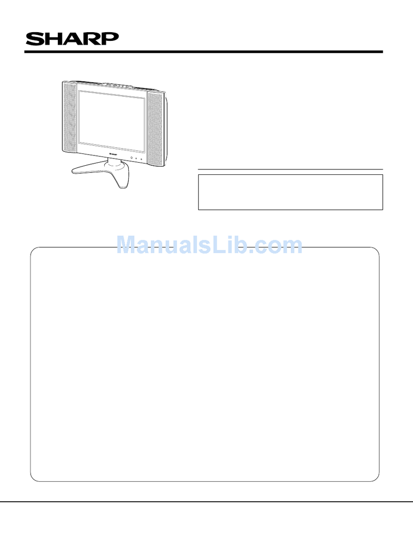
Sharp LC13-B2E User manual

1
LC-13B2E
SERVICE MANUAL
S91A2LC-13B2E
In the interests of user-safety (Required by safety regulations in some countries) the set should be restored
to its original condition and only parts identical to those specified should be used.
MODEL LC-13B2E
CONTENTS
»IMPORTANT SERVICE SAFETY
PRECAUTION.................................................... 2
»SPECIFICATIONS ............................................. 3
»OPERATION MANUAL ...................................... 4
»DIMENSIONS .................................................... 5
»REMOVING OF MAJOR PARTS ....................... 6
»ADJUSTING PROCEDURE OF
EACH SECTION ................................................ 9
»TROUBLE SHOOTING TABLE ........................ 12
»CHASSIS LAYOUT .......................................... 18
»BLOCK DIAGRAM ........................................... 20
»OVERALL WIRING DIAGRAM ........................ 24
»DESCRIPTION OF SCHEMATIC DIAGRAM .. 26
»SCHEMATIC DIAGRAM
ËOPERATION and LED UNIT ..................... 27
Page Page
ËMAIN UNIT ................................................ 28
ËTUNER UNIT ............................................. 42
ËJACK UNIT ................................................ 44
»PRINTED WIRING BOARD ASSEMBLIES ..... 45
»PARTS LIST
ËELECTRICAL PARTS ................................ 48
ËMAIN UNIT ................................................ 48
ËOPERATION UNIT..................................... 52
ËLED UNIT .................................................. 52
ËJACK UNIT ................................................ 53
ËCABINET AND MECHANICAL PARTS ..... 54
ËACCESSORIES PARTS ............................ 56
ËPACKING PARTS....................................... 56
»PACKING OF THE SET ................................... 57
SHARP CORPORATION
LCD COLORTELEVISION

2
LC-13B2E
12345678901234567890123456789012123456789012345678901234567890121234567890123456789012345678901212
1
234567890123456789012345678901212345678901234567890123456789012123456789012345678901234567890121
2
12345678901234567890123456789012123456789012345678901234567890121234567890123456789012345678901212
12345678901234567890123456789012123456789012345678901234567890121234567890123456789012345678901212
1
234567890123456789012345678901212345678901234567890123456789012123456789012345678901234567890121
2
12345678901234567890123456789012123456789012345678901234567890121234567890123456789012345678901212
SAFETY NOTICE
Many electrical and mechanical parts in LCD television
have special safety-related characteristics.
These characteristics are often not evident from visual
inspection, nor can protection afforded by them be
necessarily increased by using replacement components
rated for higher voltage, wattage and etc.
Replacement parts which have these special safety
characteristics are identified in this manual; electrical
components having such features are identified by“ å”
IMPORTANT SERVICE SAFETY PRECAUTION
ËService work should be perfomed only by qualified service technicians who are thoroughly
familiar with all safety checks and the servicing guidelines which follow:
and shaded areas in the
Replacement Parts Lists
and
Schematic Diagrams
.
For continued protection, replacement parts must be
identical to those used in the original circuit.
The use of a substitute replacement parts which do not
have the same safety characteristics as the factory
recommended replacement parts shown in this service
manual, may create shock, fire or other hazards.
WARNING
1. For continued safety, no modification of any circuit
should be attempted.
2. Disconnect AC power before servicing.
TO EXPOSED
METAL PARTS CONNECT TO
KNOWN EARTH
GROUND
DVM
AC SCALE
50k ohm
10W
0.15 µF
TEST PROBE
•Use an AC voltmeter having with 5000 ohm per volt, or
higher, sensitivity or measure the AC voltage drop
across the resisor.
•Connect the resistor connection to all exposed metal
parts having a return to the chassis (antenna, metal
cabinet, screw heads, knobs and control shafts,
escutcheon and etc.) and measure the AC voltage drop
across the resistor.
All checks must be repeated with the AC cord plug
connection reversed. (If necessary, a nonpolarized
adaptor plug must be used only for the purpose of
completing these checks.)
Any reading of 0.75V peak (this corresponds to 0.5
milliamp.peak AC.) or more is excessive and indicates
a potential shock hazard which must be corrected
before returning the monitor to the owner.
BEFORE RETURNINGTHE RECEIVER
(Fire & Shock Hazard)
Before returning the receiver to the user, perform
the following safety checks:
1. Inspect all lead dress to make certain that leads are
not pinched, and check that hardware is not lodged
between the chassis and other metal parts in the
receiver.
2. Inspect all protective devices such as non-metallic
control knobs, insulation materials, cabinet backs,
adjustment and compartment covers or shields,
isolation resistor-capacitor networks, mechanical
insulators and etc.
3. To be sure that no shock hazard exists, check for
leakage current in the following manner.
•Plug the AC cord directly into a 110~240 volt AC outlet,
and connect the DC power cable into the receiver's
DC jack.(Do not use an isolation transformer for this
test).
•Usingtwoclip leads,connecta 50kohm,10wattresistor
paralleled by a 0.15µF capacitor in series with all
exposedmetalcabinet partsandaknownearthground,
suchaselectricalconduitorelectricalgroundconnected
to an earth ground.
CAUTION: FOR CONTINUED PROTECTION
AGAINST A RISK OF FIRE REPLACE ONLY WITH
SAMETYPE FUSE. F1(2.0A, 250V), F2 (1.6A, 250V)
F4 (315mA, 250V) FUSE.
3
LC-13B2E
Specifications
LCD panel
Number of dots
Video colour system
TV-Standard (CCIR)
TV-Tuning System
TV function STEREO/BILINGUAL
AUTO PRESET
CATV
Brightness
Lamp life
Viewing angles
Audio amplifier
Speakers AV-IN 1
AV-IN 2
Terminals OUT
Antenna
Headphones
OSD language
Power requirement
Weight
Accessories
13” BLACK TFT LCD
921,600 dots
PAL/SECAM/NTSC
BG/L/DK, I, M, N
Auto preset 197 ch.
NICAM, IGR
Yes
~ Hyper Band
430 cd/m2
60,000 hours
H: 160° V: 160°
2.1 W ×2
4 ×7 cm Oval, 2 pcs.
RGB
S-VIDEO, VIDEO, AUDIO
AUDIO
DIN
3.5 mm ø jack (Rear)
English/German/French/Spanish/Italian/Swedish/Dutch
DC 12 V, AC 110–240 V, 50/60 Hz
3.8 kg, incl. stand, excl. accessories
Remote control, Btteries, AC adapter, AC cord,
Cable clamps
Items Model LC-13B2E
Specifications are subject to change without prior notice.

4
LC-13B2E
Operation Manual
Main unit (front view)
Note:
■TV/VIDEO, CH( )/( ), and Volume (+)/(–) on the main unit have the same functions as the same buttons on
the remote control. Fundamentally, this operation manual provides a description based on operation using the
remote control.
CH MENU TV/VIDEO
To change the vertical
angle of the LCD TV set,
tilt the screen up to 10
degrees forward or 20
degrees backward. The
TV set can also be
rotated 90 degrees
horizontally. Please adjust
the angle so that the TV
set can be watched most
comfortably.
Upper control panel
Volume (+)/(–)
CH ( )/( )
MENU
TV/VIDEO
(MAIN POWER)
Speaker Speaker
Remote sensor window
(The actual location is not visible.)
POWER/STANDBY indicator
A green indicator lights when the power is
on and a red indicator lights when in the
standby mode (the indicator will not light
when the main power is off).
Remote sensor indicator
A red indicator blinks when the TV set
receives the remote control signal.
Terminals
Rear view
RGB
POWER
INPUT
DC12V
L
R
AV-IN 1
AUDIO OUT
VIDEO
S-VIDEO
AUDIO
L
R
AV-IN 2
POWER INPUT
DC 12 V
Antenna
AUDIO OUT (L)
AV-IN 1
(21-pin Euro-
SCART)
AUDIO OUT (R)
HEADPHONES
VIDEO
AUDIO (L)
AUDIO (R)
S-VIDEO
Carrying handle
iE
CH
TV/VIDEO
SOUND
END
TM
MENUTEXT
(RED)(
GREEN)(
YELLOW)(
CYAN)
INFO
OK
(Power)
OK, Programme Table
INFO
Turns on the menu
information when
the menu is displayed.
Mute
TEXT
YELLOW, Standard Value
GREEN, Sound Menu CYAN, Teletext Subtitle
TV/VIDEO
Channel Select
MENU
Volume (+)/(–)
Flashback
Returns to the
previous channel.
RED, Picture Menu
Upward/Downward
Selection
END, Status Display
Turns on the status display
when the menu is not
displayed.
SOUND
Switches the sound mode.
Right/Left Selection
CH ( )/( )
Remote control

5
LC-13B2E
Dimensions
(Unit: mm)

6
LC-13B2E
REMOVING OF MAJOR PARTS
1. Remove the back cover.
2. Remove the table stand fixing screws (4 pcs.).
3. Remove the cabinet B fixing screws (9 pcs.) and detach the cabinet.
4. Peel off the tape.
5. Detach the connector from each PWB.
Cabinet B
Table stand
Back cover 1
2
33
3
3
3
4
55
5
5
555
5
5
Terminal PWB
LED PWB
Operation PWB
Main PWB
Jack PWB
Tape
SC1202
SC801
SC802
SC901
SC902
SC903
SC1201
P305 P304
P2006
P2004
P903
P901
P902
P904
P701 P702
P2005
SC5702
P5701
P4001
P5001
P3600
P4004
P3604

7
LC-13B2E
6. Remove the fixing angle fixing screws (2 pcs.).
7. Remove the terminal PWB fixing screws (3 pcs.).
8. Remove the jack PWB fixing screw (2 pc.).
9. Remove the main PWB fixing screws (1 pcs.).
10. Remove the LED PWB fixing screws (2 pcs.).
11. Remove the operation PWB fixing screws (2pcs.).
12. Remove the chassis frame fixing screws (4 pcs.)
8
7
12
Terminal PWB
Chassis Frame
Main PWB
Jack PWB
10
LED PWB
11
6
Operation PWB
9

8
LC-13B2E
»Precautions in handling the LCD panels
1. Work in a clean room (with humidities below 50%).
2. Be sure to wear an anti-static armband.
3. Handle the panels on an electroconductive mat.
4. Be careful not to fall, shake and shock the panels.
13. Remove the LCD display unit fixing screws (4 pcs.).
14. Detach the two diffusion sheets and reflection/deflection sheet.
15. Detach the four reflection mirrors.
16. Remove the fluorescent lamp.
17. Detach the lamp guide plate.
18. Detach the two lamp reflection sheets.
Reflection Mirror
Reflection Mirror
Lamp Reflection Sheet-1
(PSHEP0246CEZZ)
Light Guide Plate
(PGiDM0064CEZZ)
Fluorescent Lamp
(KLMP-0109CEZZ)
Lamp Reflection Sheet-2
(PSHEP0247CEZZ)
Diffusion Sheet
(PSHEP0244CEZZ)
Reflection/deflection Sheet
(PSHEP0245CEZZ)
LCD Display Unit
Sheilding Plate
(PSLDM4660CEFW)
13
13
14
15
15
16
17
18

9
LC-13B2E
ADJUSTING PROCEDURE OF EACH SECTION
[1] Entering the MAIN side adjustment process mode
There are three methods below.
1) Press the “Adjustment process key” on the remote control after turning on the power.
2) Pressing both the MENU key and the TV/VIDEO key on the main body, turn on the power. Then, press the
volume DOWN key and the tuning DOWN key at the same time.
3) Turn on the power with falling either KEY4 (pin (81) of microprocessor) or KEY5 (pin (82) of microprocessor) to“L”.
[Note] For the method 3), the ROM is initialized at the same time.Therefore, 3) must be executed, if IC2004 or
IC2001 is changed. For 1) or 2), the main body only enters the MAIN side adjustment process.
[2] Entering theTUNER side adjustment process mode
4) Entering the TUNER side adjustment process
MENU key on the main body →Cursor UP key (remote control) →Select the position shown in the figure below
and press the M key (remote control) within 1 second.→Enters the adjustment process.
[3] Adjustment
MAIN side adjustment (Press the “M” key to move the cursor and press the volume UP/DOWN key to make an
adjustment.)
• Power supply voltage adjustment (+B 5V)
• Model setting
• Inch size setting
• COMMON BIAS adjustment of LCD module
• CUTOFF adjustment
TUNER side adjustment (Press the tuning UP/DOWN key to move the cursor and press the volume UP/DOWN
key to make an adjustment.)
• Horizontal size adjustment (LCD adjustments)
• Video adjustment (other adjustments)
Y delay
Subcontrast
Subcolour
Subbrightness
Tint offset
AGC gain start
The TUNER side adjustment is possible. However, it is recommended to replace EAROM (I2).
Black level
Contrast
Colour
: select M: Back
E: End
Direct control at TV

10
LC-13B2E
PAL/PAL60 SECAM NTSC
y delay 7 6
RF tint offset 0 0
sub contrast 2 2
sub colour 25 25
y delay 7 5 4
AV1 tint offset 1 1 1
AV2 sub contrast 0 2 0
sub colour 30 30 20
y delay 7 5 1
AVS tint offset 1 1 1
sub contrast 0 0 0
sub colour 30 30 30
AGC gain start 23
3-1. +B adjustment
Page 9 of MAIN side adjustment process +B-ADJ
Adjust the voltage of the positive side of C753 to 5.0 ±0.05V.
3-2. Model setting
Page 9 of MAIN side adjustment process MODEL
Set to B2E.
3-3. Inch size setting
Page 9 of MAIN side adjustment process INCH SIZE
Set to 13.
3-4. COMMON BIAS adjustment of LCD module
Page 9 of MAIN side adjustment process COM BIAS
Input the picture of gray scale and adjust it so as to obtain the best contrast.
3-5. CUTOFF adjustment
Page 9 of MAIN side adjustment process R CUTOFF, B CUTOFF
Adjust it so as to obtain the optimal colour balance.

11
LC-13B2E
[4] Lamp error detection
4-1. Functional description
This LCD colour television has a function (lamp error detection) to be turned OFF automatically for safety
when the lamp or lamp circuit is abnormal.
If the lamp or lamp circuit is abnormal, or some other errors happen, and the lamp error detection is executed,
the followings occur.
1The main unit of television is turned OFF 5 seconds after it is turned ON. (The power LED on the front side
of TV turns from green to red.)
2If the situation 1happens 5 times sequentially, television can not be turned ON.(The power LED remains
red.)
4-2. Countermeasures
4-2-1.Check when turning OFF the lamp error detection
When television is turned OFF by the lamp error detection mentioned above, it enters the adjustment
process with the power LED red.Entering the adjustment process turns OFF the error detection and turns
ON TV.
This enables the operation check to detect errors in the lamp or lamp circuit.
Check whether "ERROR NO RESET" on line 7, page 1 of the adjustment process is 1 or more. If it is 1 or
more, it indicates the lamp error detection was executed.
4-2-2.Resetting of the lamp error count
After confirming that the lamp or lamp circuit is normal, reset the lamp error count. Select "ERROR NO
RESET" on line 5, page 1 of the adjustment process and set the number to 0 using the volume button.
Page 1 of the adjustment process
1 +B–A D J 160
M O D E L C2E
I NCH I SI ZE 13
N T S C PWM F R Q 0C0
ERROR NO RESET 5
P M U T E OFF
C 2 E V E R 1 . 0 0
Reset 0
Afterwards, perform the operation check to confirm that the lamp error detection does not function.

12
LC-13B2E
TROUBLE SHOOTINGTABLE
No picture, No sound
Check all the settings microprocessor's adjust process menu.
Do F2 and F4 function?
Are T701's secondary
outputs, +38V, +16V, +9V,
+5V and -8V normal?
Remove F2 and F4 and
check the load side.
Is there short-circuiting?
Is there short-circuiting of
T701 primary side periphery,
Q751, Q753 and P901.
Replace F2 and F4.
Check P901 and
connection cable.
Is T701's primary oscillator
waveform normal?
Check T701's secondary
load.
Yes Yes
No
No No
No
Yes
Fluorecent lamp failure to light up
Does F1 function?
Is the pin (34) of IC1201 in
the "H" state?
Is the Q3603 short-circuiting?
Is there short-circuiting of
T5701 and T5702 primary
side periphery, Q751~Q753.
Yes
Yes
No
No
No
Yes
Replace the fluorecent lamp
with new one and check
again.
Yes
Check the OFL1 line, IC1201
and their peripheral parts.
Check Q3603 and their
peripheral parts.
Check T5701, T5702,
Q5701~Q5703 and
connection cable.

13
LC-13B2E
TROUBLE SHOOTINGTABLE (Continued)
No picture
Check all the settings microprocessor's adjust process menu.
Is in/output of
IC801 normal?
Is in/output of
IC1201 normal?
Check IC801
and its
peripheral parts.
Check IC1201
and its
peripheral parts.
Check IC402
and its
peripheral parts.
Check IC801,
AV1 line and its
peripheral parts.
Check LCD
panel voltages
and waveform.
Yes
Yes
No
No
No picture
at all
Is in/output of
IC402 normal?
Is input at pin
(73) of IC801
normal?
Yes
No
No
No TV and
VIDEO 1
output
Is voltages at
pin (3) of W7
and pins (3), (4)
and (5) of W14
tuner normal?
Is output at pin
(2) of W7 tuner
normal?
Check the
power line.
Check tuner
and its
peripheral parts.
Is input at pin
(3) of IC402
normal?
Is the pins (2)
and (4) of IC402
at "H" and "L"
state?
Yes
Yes
No
No
No
No
No
Yes
No TV output
Is the pins (65)
and (66) of
IC2001 at "H"
and "L" state?
Yes
Check the its
line.
Check the its
line.
Check IC402
and its
peripheral parts.
Is input at pin
(1) of IC402
normal?
Is the pins (2)
and (4) of IC402
at "L" state?
Check the its
line.
Check the its
line.
Check IC402
and its
peripheral parts.
Is the pins (65)
and (66) of IC2001
at "L" state?
Yes
Yes
No
No
No
No VIDEO 1
output

14
LC-13B2E
TROUBLE SHOOTINGTABLE (Continued)
No picture
Check all the settings microprocessor's adjust process menu.
Is input at pin
(74) of IC801
normal?
Check the AV2
line and their
peripheral parts.
Check the W9,
SY-line, SC-line
and their
peripheral parts.
No
No VIDEO 2
output
Is input at pins
(71) and (72) of
IC801 normal?
No
No S-VIDEO
output
Is input at pin
(70) of IC801
normal?
Check the
V2VO line and
their
peripheral parts.
No
No line
output
Is input at pins
(1), (2), (3), (56),
(57) and (79) of
IC801 normal?
Is output at pins
(11), (13) and
(16) of I4
normal?
Check IC801
and its
peripheral parts.
Check I13 and
its
peripheral parts.
Check I9 and
its
peripheral parts.
Check I4 and
its
peripheral parts.
Is output at pins
(11), (13) and
(16) of I13
normal?
Yes
Yes
No
No
No
No TELETEXT
output
Is output at pins
(44)~(49) of I9
normal?
Yes
No

15
LC-13B2E
TROUBLE SHOOTINGTABLE (Continued)
No picture
Check all the settings microprocessor's adjust process menu.
Is source GND
normal?
Is CSCOM
waveform
normal?
Check R1212
and its
peripheral parts.
Check IC1109,
Q1101, Q1102,
D1101, R1120,
R1130 and their
peripheral parts.
Check R1231
and its
peripheral parts.
Yes
No
No
Becomes
dark
No
Time passes,
becomes
dark
Is gate GND
normal?
Is gate clock
(GCK) normal?
Check R1223
and gate aray
peripheral parts.
Yes
No
Check D1201
and its
peripheral parts.
No
Is B-5.5V being
outputted?
Is VCC being
outputted?
Check T701's
secondary +5V
outputs line.
Yes
No
Is GSP
waveform
normal?
Check R1223
and its
peripheral parts.
Yes
No
Becomes
white.
Is 3.3V VHS
being
outputted?
Is source clock
normal?
Check +3.3V
outputs line of
IC752.
Check R1210,
R1211 and their
peripheral parts.
Check FB1203
and gate aray
peripheral parts.
Is output of LBR
and HG
normal?
Yes
Yes
No
No
No
Vertical line
output

16
LC-13B2E
TROUBLE SHOOTINGTABLE (Continued)
No picture
Check all the settings microprocessor's adjust process menu.
Is output of
R0~R5
normal?
Is output of
G0~G5
normal?
Is output of
B0~B5
normal?
Check R1202,
R1203 and their
peripheral parts.
Check R1204,
R1205 and their
peripheral parts.
Check R1206,
R1207 and their
peripheral parts.
Check T701's
secondary +5V
outputs line.
Yes
Yes
No
No
Colour is
unusual
Is VLS 5V
being
outputted?
No
Picture
image is
gloomy
Is in/output of
SPIO and
SPOI normal?
Check R1209
and their
peripheral parts.
No
No picture
image
inversion
Is output V0,
V16, V32, V48
and V63
normal?
Check IC1106,
IC1107, IC1108
and their
peripheral parts.
No
Gradation
defect
Is output of U/D
normal?
Check Q1201
and their
peripheral parts.
Yes
No

17
LC-13B2E
No sound
Check all the settins microprocessor's adjust process menu.
Is the pin (53) of
IC2001 in the
"L" state?
Is output at pins
(26) and (27) of
IC901 normal?
Is output at pins
(1) and (7) of
IC903 normal?
Yes
Yes
No
No
No
No
No
No sound
from front
speakers
Is output at pins
(1) and (7) of
IC303 normal?
Yes
Is output at pins
(8) and (12) of
IC3305 normal?
Yes
Muting effect is
on. Check the
FSMUTE line.
Check IC901
and its
peripheral parts.
Check IC903
and its
peripheral parts.
Check IC303
and its
peripheral parts.
Check IC3305
and its
peripheral parts.
Check front
speaker and
connection
cable.
Yes
Is the pin (53) of
IC2001 in the
"L" state?
Is output at pins
(26) and (27) of
IC901 normal?
Is output at pins
(1) and (7) of
IC903 normal?
Yes
Yes
No
No
No
No
No
No
Is output at pins
(1) and (7) of
IC303 normal?
Yes
Is output at pins
(8) and (12) of
IC3305 normal?
Yes
Muting effect is
on. Check the
FSMUTE line.
Check IC901
and its
peripheral parts.
Check IC903
and its
peripheral parts.
Check IC303
and its
peripheral parts.
Check IC3305
and its
peripheral parts.
Yes
Is output at
Q301 normal?
Check Q301
and connection
cable.
No sound
from
headphone
TV sound
failure
Is output at pins
(37) and (38) of
IC901 normal?
Is output at pins
(1) and (7) of
IC902 normal?
Check IC901
and its
peripheral parts.
Check IC902
and its
peripheral parts.
Yes
No No
No
No sound
from output
line
Is output at pin
(1) of W7 tuner
normal?
Is input at pin
(67) of IC901
normal?
Check the tuner
and its
peripheral parts.
Check IC901,
MONOS/SIF
line and their
peripheral parts.
Yes
No
TROUBLE SHOOTINGTABLE (Continued)

1918
LC-13B2E
121110987654321
A
B
C
D
E
F
G
H
CHASSIS LAYOUT
MAIN Unit (Side A)
MAIN Unit (Side B)
JACK Unit
OPERATION Unit LED Unit
TERMINAL Unit

2120
LC-13B2E
121110987654321
A
B
C
D
E
F
G
H
BLOCK DIAGRAM
ËTUNER Block Diagram
I2C bus
AV1
INPUT/
OUTPUT
TUNER
INPUT
AV
OUTPUT
AV1
INPUT/
OUTPUT
ANT
INPUT
AV
OUTPUT
SCL, SDA
H
V
R_VPC, G_ VPC, B_VPC
SUBCLK
SUBIN
SUBOUT
M/S IN
M/S OUT
V OUT VPC
SC1 OUT L/R MSP
V IN3 VPC
SC2 IN L/R MSP
V IN2 VPC
AN IN1 MSP
SC2 OUT L/R MSP
SC902
I2C
I2C
I2C
OSD
SC802
DC 12V
HR
HL
P904
ANALOG SWITCH
I4
MICON
I9
ANALOG SWITCH
I13
R_OSD, G_OSD, B_OSD
H
V
TUNER
W7, W14
SOUND(L/R)
RF
AV1 SOUND(L/R)
AV1 PICTURE
R_SCART, G_SCART, B_SCART
AV1 SOUND OUTPUT(L/R)
AV1 PICTURE OUTPUT
SCL, SDA
I2C
I2CE2PROM
I2
ROM
I3
MEMORY
I6
DC JACK
HEAD PHONE
JACK
J3702
SC903
J902
J903

2322
LC-13B2E
121110987654321
A
B
C
D
E
F
G
H
ËMAIN Block Diagram
LAMP
T5701~T5702
DC/AC
TRANCE
LAMP ERROR
DET
L_ERR
COMMON DRIVE
IC1109
CSCOM
LCD
PANEL
V0,V16,V32
V48,V64
DAC
IC1101
MP_CLK, MPDA, DAC1CS
CS
GRADUATION
POWER FOR
LCD
IC1102~IC1108, IC1110
R0~R5, G0~G5, B0~B5, CK
FRONT SPEAKER
L/R
FLSP
FRSP
GCK
PA VCC
AUDIO
AMPLIFER
IC3305
PA DC12V
ANALOG MULTIPLEXER
IC1205
L/R
REVERSE
IC303
FIFO
IC1202
LPF
IC903
AUDIO
AMPLIFER
IC304
LCD
CONTROLLER
IC1201
OFL1
DC/AC
INVERTER
DRIVE
Q3603
Q5701~Q5703
INV VCC
INV
DC12V
KEY
REMOTE CONTROL
RECEIVER
RESET
IC2002
CS
E
2
PROM
IC2004
I
2
C
I
2
C
I
2
C
I
2
C
MICON
IC2001
MP_CLK, MPDA, DAC1CS
CONTROL SIGNAL
LLC1, LLC2, FIELD
VSY
HSY
UV0~UV7, VP_Y0~VP_Y7
DACM_L/R
DACA_L/R
MSP
IC901
VPC
IC801
HSY
ANALOG
SWITCH
IC2007
HSY2
HD
CSYNC
+5V
+31V
+14V
+8V
+38V
+16V
+9V
+5V
-8V
+3.3V
+3.3V REG
IC752
IC201
Q204
Q202
Q203
+5V REG IC751
DC/DC
T701
PWM
IC702
INV DC 12V
PA DC 12V
PA VCC
INV VCC
SIG VCC
DC 12V
OSD
S INPUT
AV2 INPUT
AV1
INPUT/
OUTPUT
TUNER
INPUT
HR
HL
AV
OUTPUT
P901
OSDHD
V1 SC
V1 SY
V1 IN
V1 L/R
V2 VO
V2 LO/RO
V2 V
V2 L/R
TV V
SIF
SC2 OUT L/R
SC902
J5001
SC5001
OSDVD
OSDR, OSDG, OSDB
SUBCLK, SUBIN, SUBOUT, M/S IN, M/S OUT
SC801
CSYNC
SYNC SEPARATE
IC401
SC
AV3
VO
AV2
AV1
BUFFER
IC902
TV/AV
SELECTION
IC402
I
2
C bus SCL, SDA I
2
C
P2004
Other manuals for LC13-B2E
2
Table of contents
Other Sharp TV manuals

Sharp
Sharp LC-19A33X-BK User manual

Sharp
Sharp 32U-S600 User manual

Sharp
Sharp 29F-PE550 User manual

Sharp
Sharp AQUOS LC-52LE640U User manual

Sharp
Sharp LC-20B2UA User manual

Sharp
Sharp 50EQ3KA User manual

Sharp
Sharp AQUOS LC-60EQ30U User manual

Sharp
Sharp 32U-F500 User manual

Sharp
Sharp 70AS-06S User manual

Sharp
Sharp CL20S10 User manual

Sharp
Sharp 26SL72 User manual

Sharp
Sharp 36R-S60 User manual

Sharp
Sharp EQ Series User manual

Sharp
Sharp 21H-FT1 User manual

Sharp
Sharp 20AG2-SMK3 User manual

Sharp
Sharp 32C540 User manual

Sharp
Sharp LC-32LD164E User manual

Sharp
Sharp 19L-M100 User manual

Sharp
Sharp 21B-FX5 User manual

Sharp
Sharp 27U-F500 User manual