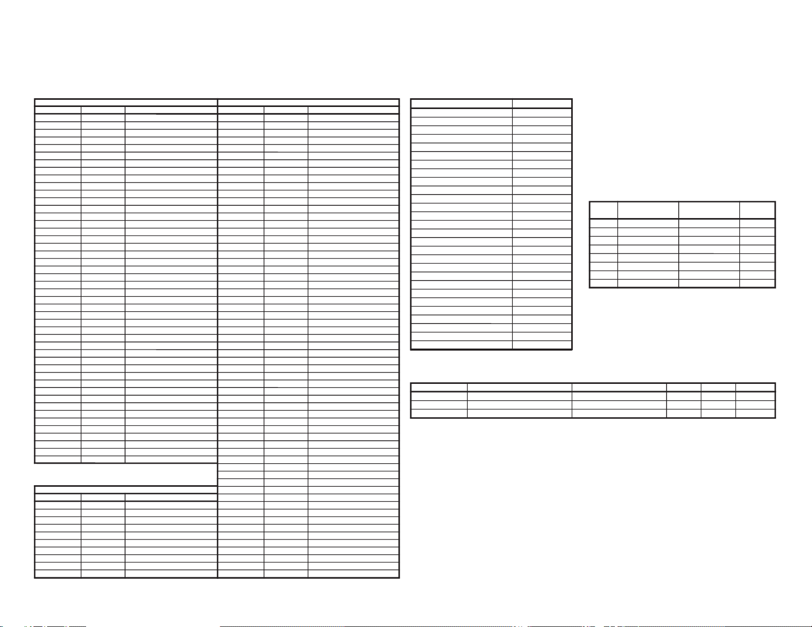
EEPROM ITEMS OSD DATA LENGTH
INITIAL DATA
FIX/ADJ REMARK
AGC Take Over Point AGC 0 ~ 63 14 (20) ADJ
Vertical Slope V-LIN 0 ~ 63 32 ADJ
Vertical Amplitude V-AMP 0 ~ 63 32 ADJ
Vertical Shift V-CENT 0 ~ 63 32 (15) ADJ
Horizontal shift H-CENT 0 ~ 63 32 ADJ
East-West width H-SIZE 0 ~ 63 32 FIX
Horizontal Parallelogram EW / / 0 ~ 63 32 FIX
East-west Parabola/Width PARA 0 ~ 63 32 FIX
East-west Upper Corner Parabola COR (U) 0 ~ 63 32 FIX
East-west Lower Corner Parabola COR (L) 0 ~ 63 32 FIX
East-west Trapezium TRAPE 0 ~ 63 32 FIX
Horizontal Bow HB 0 ~ 63 32 FIX
S-Correction S-COR 0 ~ 63 0 (24) FIX
White point Red Standard white temp. DRI-RS 0 ~ 63 32 FIX
White point Green Standard white temp. DRI-GS 0 ~ 63 32 ADJ
White point Blue Standard white temp DRI-BS 0 ~ 63 32 ADJ
White point Red Cold white temp. DRI-RC 0 ~ 63 25 FIX *2
White point Green Cold white temp. DRI-GC 0 ~ 63 32 FIX *2
White point Blue Cold white temp. DRI-BC 0 ~ 63 32 FIX (DRI-BS) DATA
White point Red Warm white temp. DRI-RW 0 ~ 63 32 FIX
White point Green Warm white temp. DRI-GW 0 ~ 63 32 FIX (DRI-GS)-7 DATA
White point Blue Warm white temp. DRI-BW 0 ~ 63 32 FIX (DRI-BS)-7 DATA
Max Volume SUB-VOL 0 ~ 60 60 FIX
Sub Contrast SUB-CON 0 ~ 63 63 FIX
Sub Colour SUB-COL 0 ~ 63 32 (20) ADJ
Sub Brightness SUB-BRI 0 ~ 63 32 (20) ADJ
Sub Tint SUB-TINT 0 ~ 63 32 (30) ADJ
Sub Sharpness SUB-SHP 0 ~ 63 32 FIX
Max Hotel Volume HTL-VOL 0 ~ 60 30 FIX
Hotel Program number HTL-PRG
0 ~ 99 OR >99 FOR NONE
255 FIX
Blue Back Contorast BB-CON 0 ~ 15 10 FIX
OSD RGB Reference RGB 0 ~ 15 15 (8) FIX
Black Level off-set R CUT-R 0 ~ 63 32 ADJ
Black Level off-set G CUT-G 0 ~ 63 32 ADJ
Cathode Drive Level CDL 0 ~ 15 0 (9) FIX
Y-Delay time for PAL (TV) DL-PT 0 ~ 15 12 FIX
Y-Delay time for SECAM (TV) DL-ST 0 ~ 15 15 FIX
Y-Delay time for N358 (TV) DL-3T 0 ~ 15 12(5) FIX
Y-Delay time for N443 (TV) DL-4T 0 ~ 15 12(5) FIX
Y-Delay time for B/W (TV) DL-TV 0 ~ 15 12 FIX
Y-Delay time for PAL (AV) DL-PA 0 ~ 15 12 FIX
Y-Delay time for SECAM (AV) DL-SA 0 ~ 15 15 FIX
Y-Delay time for N358 (AV) DL-3A 0 ~ 15 12(5) FIX
Y-Delay time for N443 (AV) DL-4A 0 ~ 15 12(5) FIX
Y-Delay time for B/W (AV) DL-AV 0 ~ 15 12 FIX
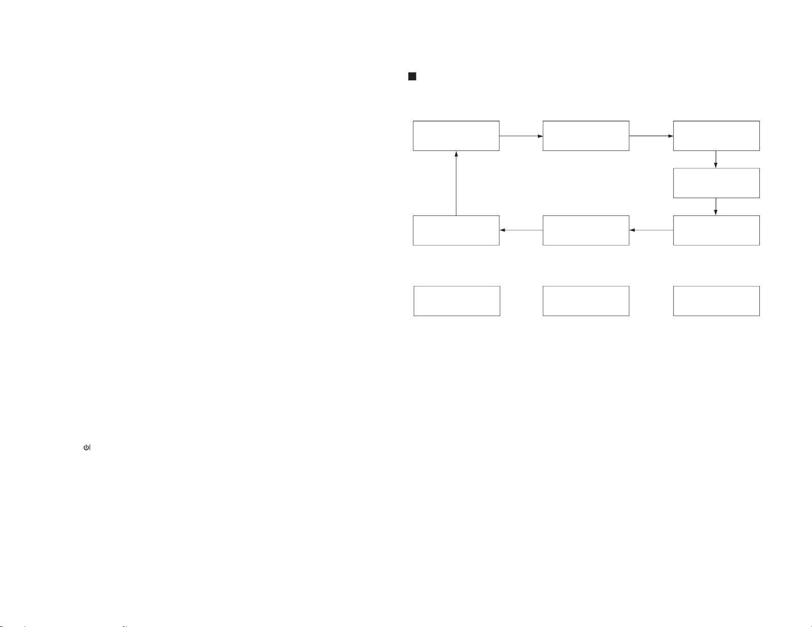
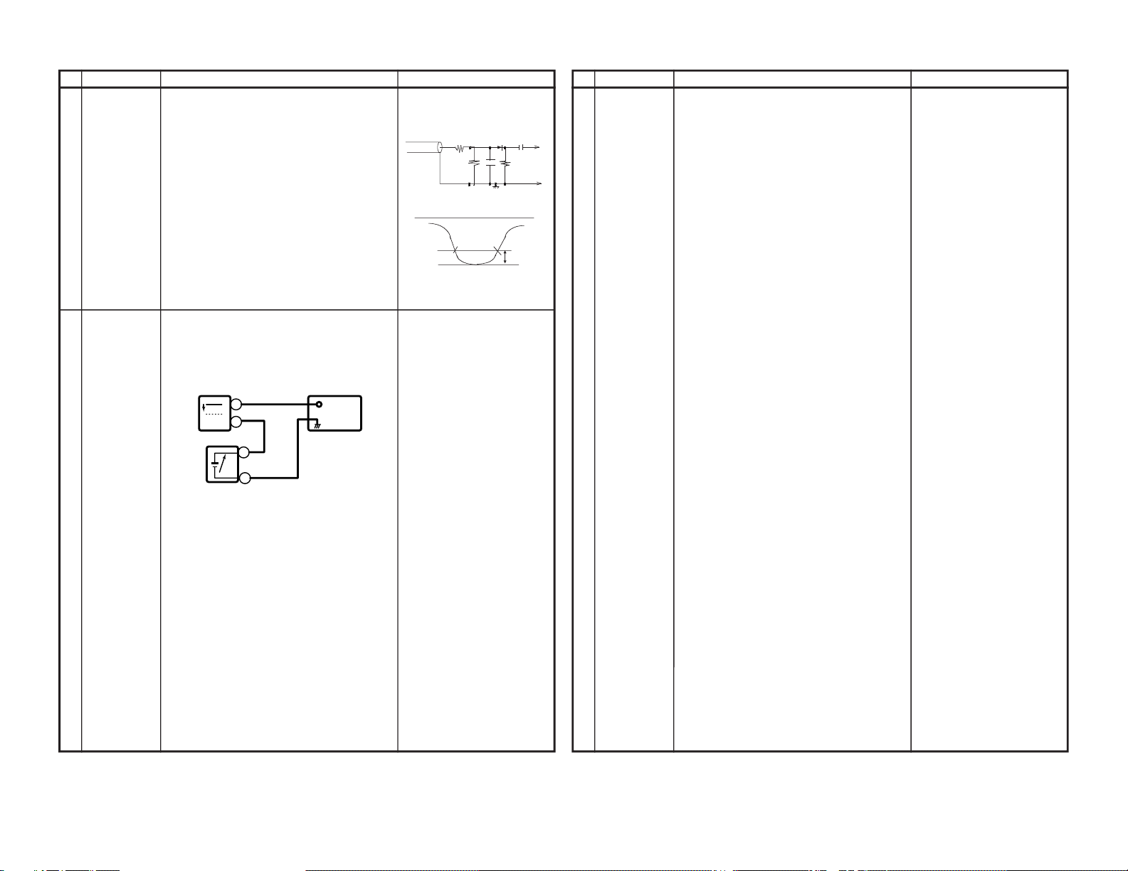
After short TP1001 & TP1002, and turn on the MAIN POWER switch, read data from EEPROM address
00H ~ 03H, and compare to the list below, if different, initialize the EEPROM.
Address : Data Address : Data
00H : 55H 02H : 53H
01H : 41H 03H : 36H