8-1 8-2
8
21GT-22
1. Call " SUB-BRI" in service mode. (Receive Cross-
hatch pattern with 5 black level windows)
2. Adjust the " SUB BRIGHT " bus data in order that
the line 1and 2 have the same darkness wherelse
line 3 is one step (data) brighter than line 2. Finally
data minus 1 to make line 1, 2, and 3 are in same
level (darkness).
Remark
1. Before CRT cutoff adjustment, SUB-BRIGHT, DRI-
RS/RW/RC, DRI-GS/GW/GC, DRI-BS/BW/BC,
CUT-R and CUT-G must be INITIAL DATA.
2. CRT Cutoff adjustment must be done inside a dark
room.
1. Switch TV to VIDEO mode,BLUE BACK OFF, with
NO VIDEO signal.
2. Press R/C to set Picture Normal condition.
3. First, off the screen by adjust screen variable resistor.
*4.Next,checkingAKB circuitfunction by slowlyincrease
screen variable resistor until colour raster suddenly
on and off (AKB start function).
5. Then continue adjust until retrace line appear.
6. Finally, slowly decrease the screen variable resistor
until screen retrace line cut off (Not Raster)
Note :
Must confirm theAKB function in set before continue
the next adjustment.
CRT CUT-OFF, BACKGROUND AND SUB-CONTRAST ADJUSTMENT
NO. Adjustment part Adjusting procedure and conditions Waveform and others
1
2 SUB-
BRIGHTNESS
ADJUSTMENT
(I2C BUS
CONTROL)
Line 3 is one step (data) brighter than line 2
CRT CUTOFF
ADJUSTMENT
(I2C BUS
CONTROL)
3 WHITE
BALANCE
SERVICE
MODE ADJ.
(I2C BUS
CONTROL)
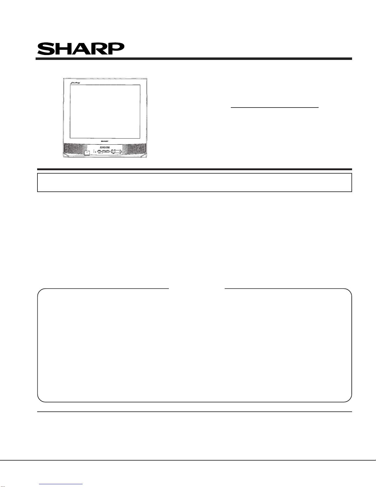
1. Receive the "WHITE" pattern with BURST signal.
2. Press R/C to set Picture NORMAL condition.
3. Connect the DC miliammeter between TP602 (-)
TP603 (+).
4. Check Beam current should be around 1100 µA.
5. Set it to service mode and adjust the DRI-GS, & DRI-
BS data to have a colour temperature of 12300°K (
white ). * Note .
6. Receive "WHITE" pattern, WITH BURST signal, and
set BRIGHTNESS Y by generator, to **10 cd/m2
(MINOLTA CA-100) by reducing LUMINATE Y sig-
nal.
7. Adjust "CUT-R" & "CUT-G" to get desired colour tem-
perature #. Then go back NORMAL mode (HIGH
BRIGHT**) to check colour temperature.
If out of range, back to 1.
Note:This adjustment must be done after warm-
ing up the unit for 30 minutes or longer with
a beam current over 700µA.
* Adjust DRI-GC/GW, DRI-BC/BW as following DATA,
after finishing DRI-BS and DRI-GS DATAADJUST-
MENT.
DRI-RW = 32 (FIXED), DRI-RS = 32 (FIXED)
DRI-BC = "DRI-BS"
(For 12300°K Condition)
# 12300°K X : 0.272
Y : 0.275
(MINOLTACOLOURANALYZER CA-
100)
*Note:Above Data can be UP/DOWN
by Volume key.
LOW HIGH
21" 10cd/m2 120cd/m2
4 Max.
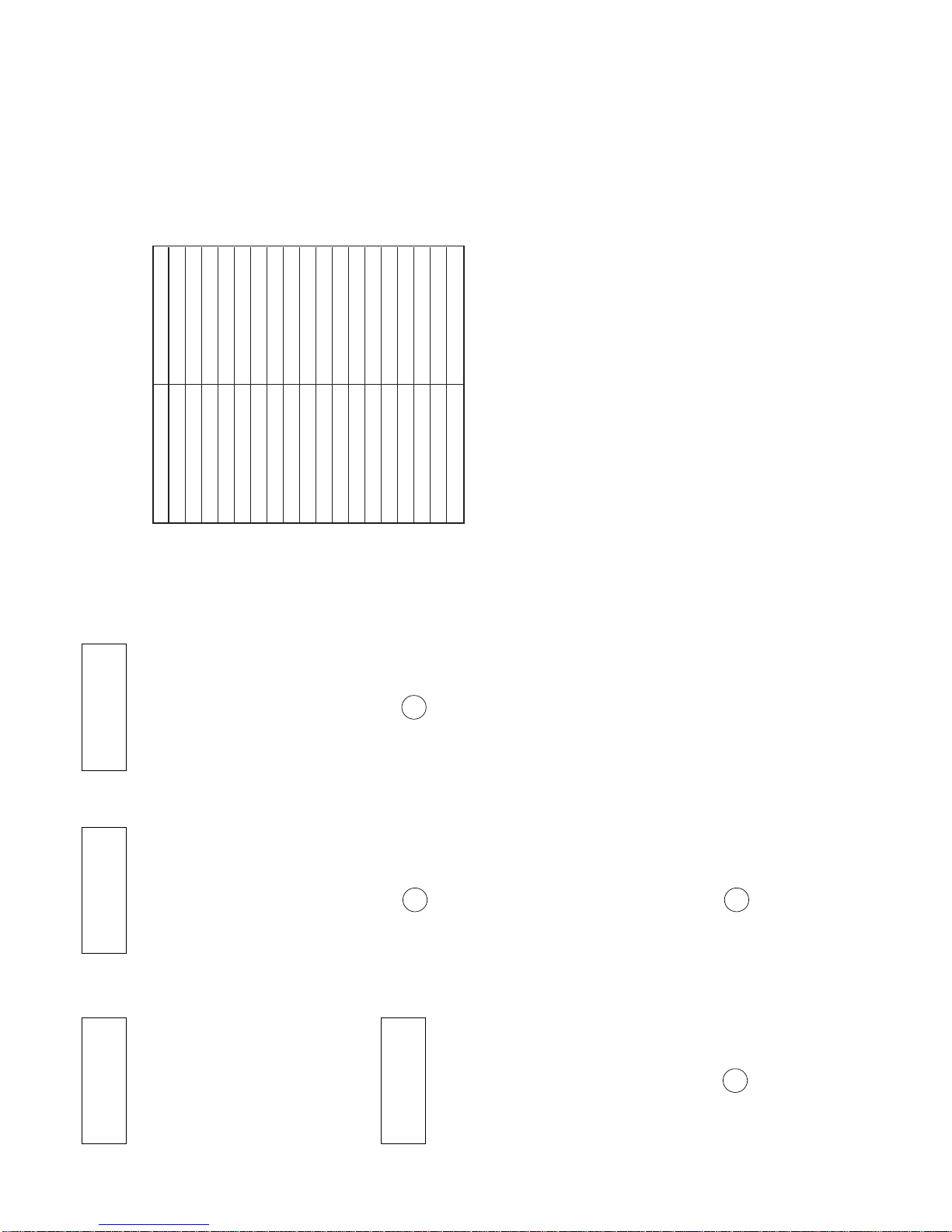
beam check 1. Receive the "Monoscope Pattern" signal.
2. Press R/C to set Picture NORMAL condition.
3. Connect the DC miliammeter between TP603 (+) &
TP602 (–).
(Full Scale: 3 mA Range)
4.
Beam current must be within 1100 ±100 µA.
1 2 3 4 5
t
3.2Vdc
0
*Alternative Procedure
(1) Step (1), (2), (3) and (4) are same
as beside procedure.
(2) Then continue adjust until retrace
line appear and make sure the col-
our appear whether red, green or
biue.
(3) Connect the oscilloscope to related
test points as below which is based
on colour appear at (2) RED=TP47R,
GREEN=TP47G,BLUE=TP47B
(4) Then adjust Screen VR until the tip
of signal reach 3.2Vdc.
1 2 3 4 5
1
2
* 12300°K DRI-GW="DRI-GS"-7
DRI-BW="DRI-BS"-7
DRI-GC="DRI-GS"-7
DRI-RC=25
HORIZONTAL AND VERTICAL DEFLECTION LOOP ADJUSTMENT
NO. Adjustment part Adjusting procedure and conditions Waveform and others
1
2
3
4
5
6
V-SLOPE (I2C
BUS CON-
TROL)
V-SHIFT-50
(I2C BUS
CONTROL)
V-AMP50
(I2C BUS
CONTROL)
H-SHIFT (50)
(H-CENTER)
S-CORREC-
TION (I2C BUS
CONTROL)
SUB-
SHARPNESS
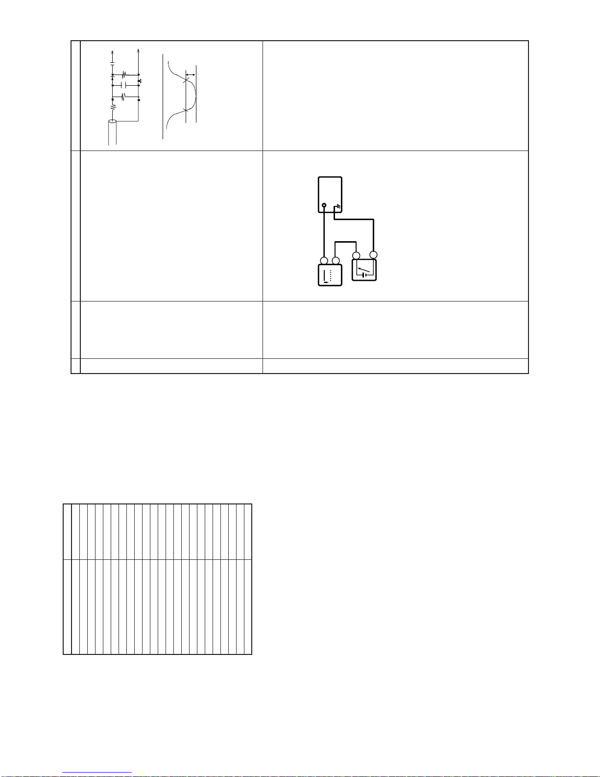
1. Receive Monoscope Pattern Signal.
2. Call the "V-LIN" mode.
3. Increase or decrease "V-LIN" by Volume key
till the horizontal line in the center of
monoscope is just at the position where the
blanking starts.
1. Call the "V-CENT" mode.
2. Increase or decrease "V-CENT" by Volume key
till the picture is centered.
1. Call the "V-AMP" mode.
2. Increase or decrease "V - AMP" by Volume
key to set overscan of 9.5% typical.
Adjustment Spec 9.5% range +1% -0%.
1. Call the "H-CENT" mode.
2. Increase or decrease"H-CENT"byVolume key
to center the picture horizontal.
1. SET DATA TO 20
* Check the E-5 CH Monoscope Pattern then re-
adjustV-Slope,V-Shift and V-Ampto makesure
adjustment is in acceptable Ring-Shaped.
1. SET DATA TO 20
PAL CHROMA ADJUSTMENT
NO. Adjustment part Adjusting procedure and conditions Waveform and others
1 SUB COLOUR
(I2C BUS
CONTROL)
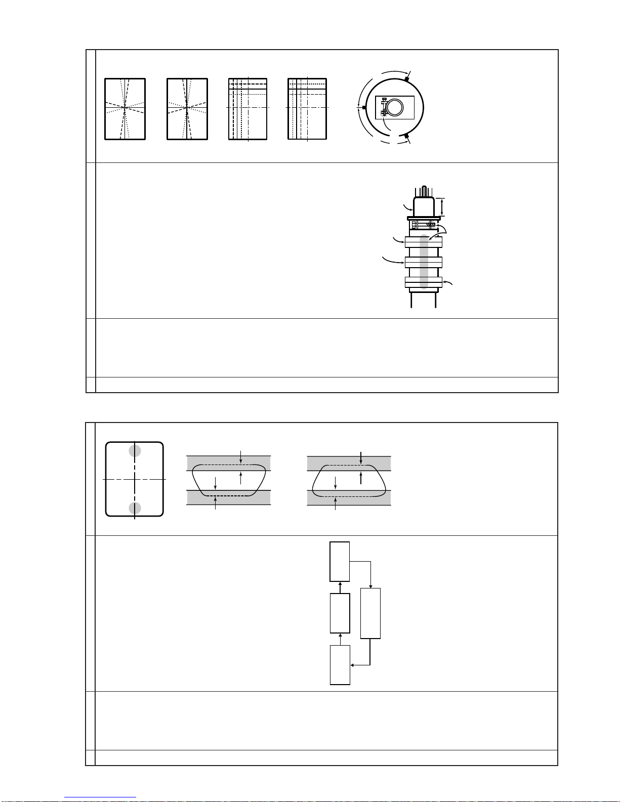
1. Receive the "PAL Color Bar" signal.
2. Press R/C to set Picture Normal condition.
3. Connect the oscilloscope to
Red cathode(D882 Chathode) for 21" (Normal
Neck).
»Range : 20 V/div. (AC) (Using 10:1 probe)
»Sweep time : 10 µsec/div.
4. Using the R/C call "SUB COL" in SERVICE
mode.Adjust SUB COLOUR bus data, so that
the 75% White & Red portions of PAL Color
Bar be at the same level shown as Fig. 1-1.
5. Add another 6 steps up into the value of SUB-
COL obtained in 4.
6. Clear the SERVICE Mode.
1 Focus 1. Receive the "Monoscope Pattern" signal.
2. Press R/C to set Picture NORMAL condition.
3. Adjust the focus control to get the best focus-
ing.
Fig. 1-1
Cy GB
WY 100%W
75% Mg R