9
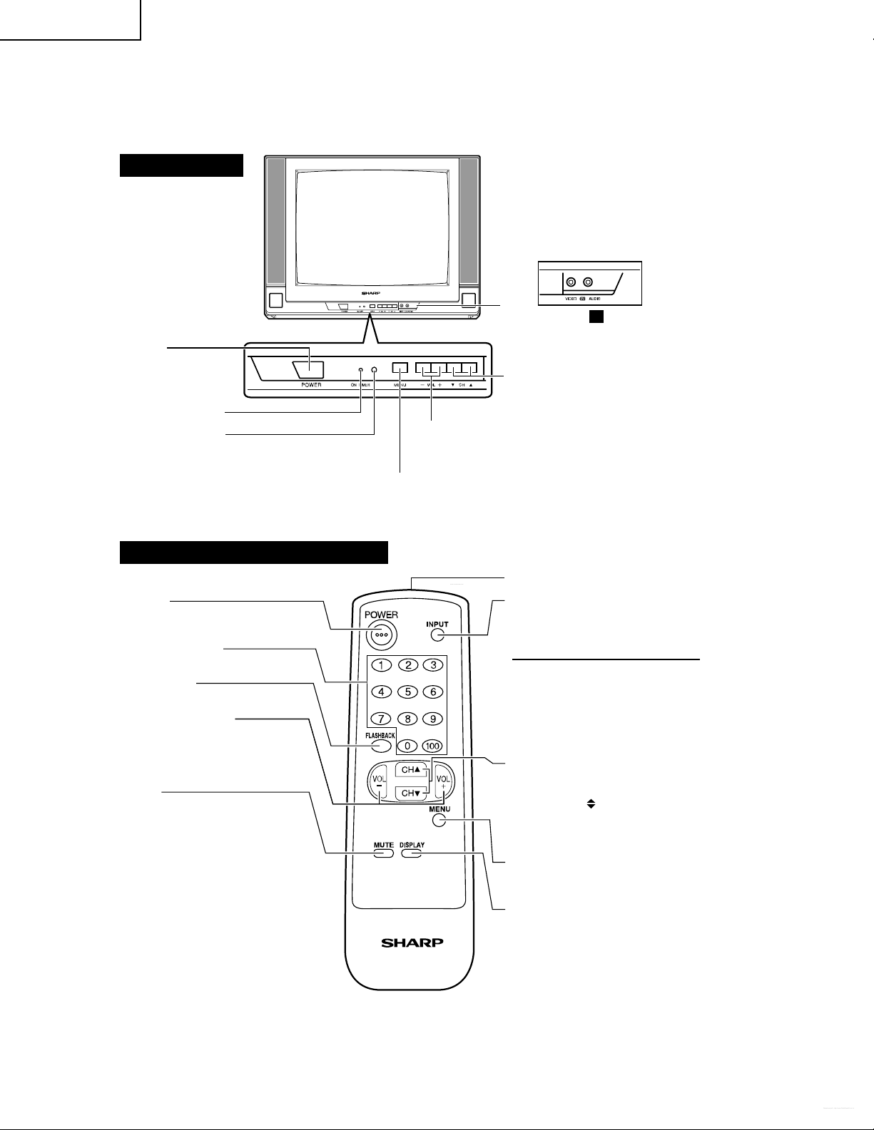
20SL43
SERVICE
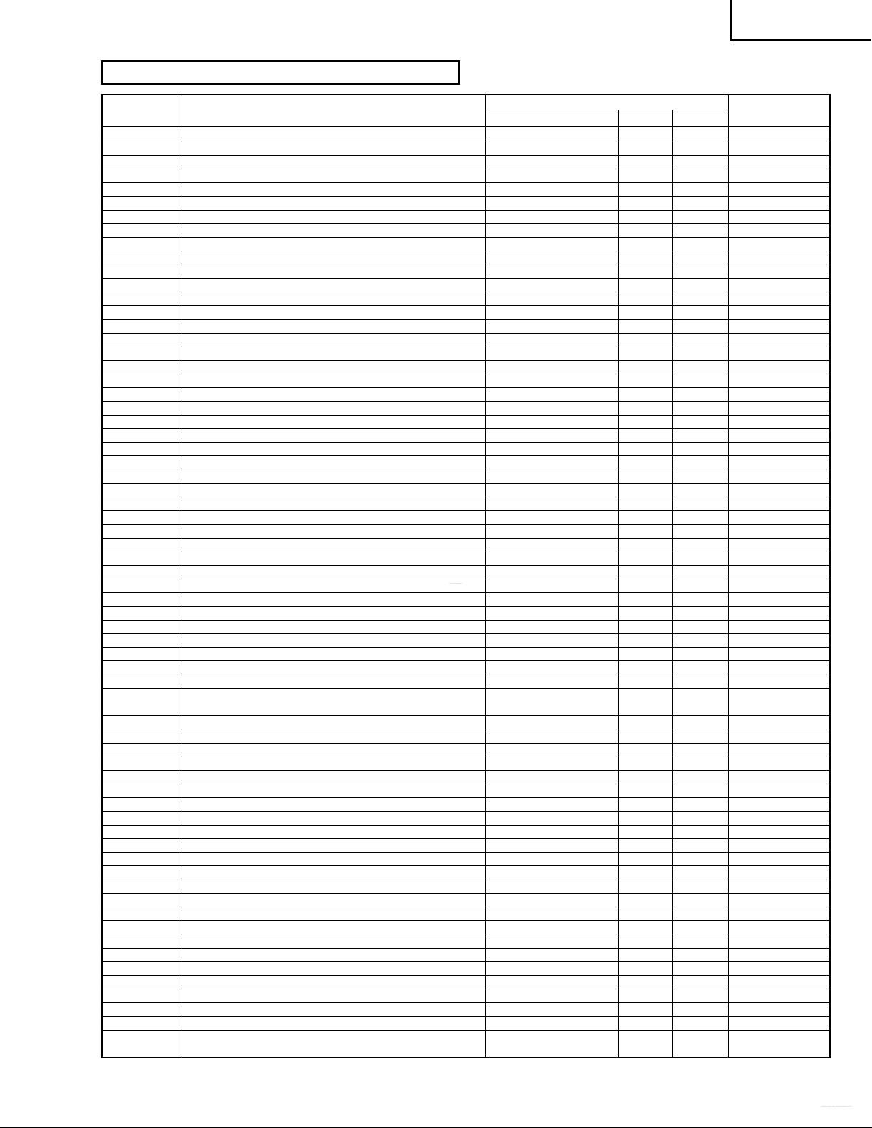
POSITION ADJUST ITEM DATA
RANGE
INITIALVALUE
FIX/ADJ REMARK
AGC AGC TAKE OVER POINT 0~63 14 ADJ
V-LIN VERTICAL SLOPE 0~63 32 ADJ
V-AMP VERTICAL AMP 0~63 32 ADJ
V-CENT VERTICAL SHIFT 0~63 32 ADJ
V-ZOOM VERTICAL ZOOM 0~63 32 FIX
H-CENT HORIZONTAL SHIFT 0~63 32 ADJ
H-SIZE EAST-WEST WIDTH 0~63 32 FIX
EW// HORIZONTAL PARALLELOGRAM 0~63 32 FIX
PARA EAST-WEST PARABOLA / WIDTH 0~63 32 FIX
COR(U) EAST-WEST UPPER CORNER PARABOLA 0~63 32 FIX
COR(L) EAST-WEST LOWER CORNER PARABOLA 0~63 32 FIX
TRAPE EAST-WEST TRAPEZIUM 0~63 32 FIX
HB HORIZONTAL BOW 0~63 32 FIX
S-COR S-CORRECTION 0~63 0 FIX must be "17"
DRI-R-HI “W,P RED OFFSET HIGH / OFFSET BLUE TONE” 0~63 32 FIX must be "32"
DRI-G-HI W.P. GREEN OFFSET HIGH / OFFSET BLUE TONE 0~63 32 FIX must be "33"
DRI-B-HI W.P.BLUE OFFSET HIGH / OFFSET BLUE TONE 0~63 32 FIX must be "37"
DRI-R-MH W.P. RED MH / STD 0~63 25 FIX must be "32"
DRI-G-MH W.P. GREEN MH / STD 0~63 32 ADJ
DRI-B-MH W.P. BLUE MH / STD 0~63 32 ADJ
DRI-R-ML W.P. RED OFFSET ML / OFFSET RED TONE 0~63 32 FIX must be "32"
DRI-G-ML W.P. GREEN OFFSET ML / OFFSET RED TONE 0~63 32 FIX must be "32"
DRI-B-ML W.P. BLUE OFFSET ML / OFFSET RED TONE 0~63 32 FIX must be "25"
DRI-R-LO W.P. RED OFFSET LOW 0~63 32 FIX must be "32"
DRI-G-LO W.P. GREEN OFFSET LOW 0~63 32 FIX must be "22"
DRI-B-LO W.P. BLUE OFFSET LOW 0~63 32 FIX must be "19"
SUB-VOL MAX VOLUME 0~63 63 FIX must be "63"
SUB-CON SUB CONTRAST 0~63 63 FIX must be "54"
SUB-COL SUB COLOUR 0~63 32 ADJ
SUB-BRI SUB BRIGHTNESS 0~63 32 ADJ
SUB-TINT SUB TINT 0~63 32 ADJ
SUB-SHP SUB SHARPNESS 0~63 32 FIX must be "27"
HTL-VOL MAX HOTEL VOLUME 0~63 32 FIX
HTL-PRG HOTEL PROGRAM NO 0~125 or >125 for none 255 FIX
BB-CON BLUE BACK CONTRAST 0~15 10 FIX must be "5"
RGB OSD GRB REFERENCE 0~15 15 FIX must be "5"
CUT-R BLACK LEVEL OFFSET R 0~63 32 ADJ
CUT-G BLACK LEVEL OFFSET G 0~63 32 ADJ
CDL CATHODE DRIVE LEVEL 0~15 0 FIX must be "6"
DL-TV Y-D TIME (TV) [YD ] 0~15 12 FIX must be "2"
DL-AV Y-D TIME (AV) [YD ] 0~15 12 FIX must be "8"
INIT INITIAL/DEFAULT LANGUAGE 0(English), 1(Spanish), 0 FIX must be "1"
2(French)
FAO-VOL FAO-MAXVOLUME 0~63 63 FIX must be "63"
ESV_OFFS ENERGY SAVE OFFSET 0~63 10 FIX must be "20"
CCPOS CLOSE CAPTION POSITION 0~255 32 ADJ
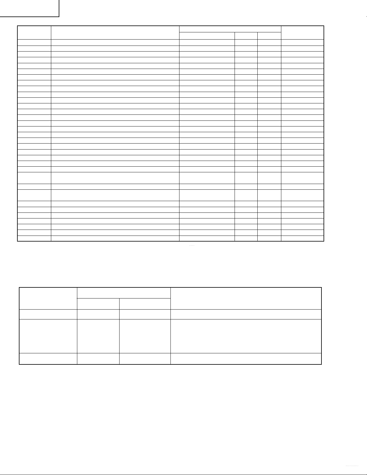
ATT ATTENUATE INPUT SIGNAL LEVEL 0~15 10 FIX*
VCO VCO FREE RUNNING FREQUENCY ADJ. 0~63 32 FIX*
FILTER “STEREO, SAP, DBX FILTER ADJ.“0~63 28 FIX*
WIDEBAND STEREO SEPARATION ADJUSTMENT (300HZ) 0~63 32 FIX*
SPECTRAL STEREO SEPARATION ADJUSTMENT (3kHZ) 0~63 27 FIX*
BASS BASS LEVEL 0Å‘15 8 FIX
TREBLE TREBLE LEVEL 0Å‘15 8 FIX
VSD VERTICAL SCAN DISABLE 0 or 1 when item selected 0 FIX
BKS BLACK STRETCH 0(disable) or1(enable) 1 FIX
AVL AUTOMATIC VOLUME LEVELLING 0(disable) or1(enable) 1 FIX
FFI FAST FILTER IF-PLL 0(disable) or1(enable) 0 FIX
EVG ENABLE VERTICAL GUARD 0(disable) or1(enable) 1 FIX
EHT EHT TRACKING MODE 0(disable) or1(enable) 1 FIX
OSO OVERSCAN SWITCH OFF 0(disable) or1(enable) 0 FIX
ACL AUTO COLOUR LIMIT 0(disable) or1(enable) 0 FIX
FCO FORCED COLOUR-ON 0(disable) or1(enable) 0 FIX
VMI VIDEO MUTE AT IDENT LOSS 0(disable) or1(enable) 1 FIX
VMC VIDEO MUTE AT PROGRAM/SOURCE CHANGE 0(disable) or1(enable) 1 FIX
HTL HOTEL MODE 0(disable) or1(enable) 0 FIX
BTSC GAIN FM DEMODULATOR 0(disable) or1(enable) 0 FIX
CP CHARGE PUMP 0(fast tuning) or 1 0 FIX
(moderate speed tuning)
SERVICE MODE
Table - A
Datasheet pdf - http://www.DataSheet4U.co.kr/