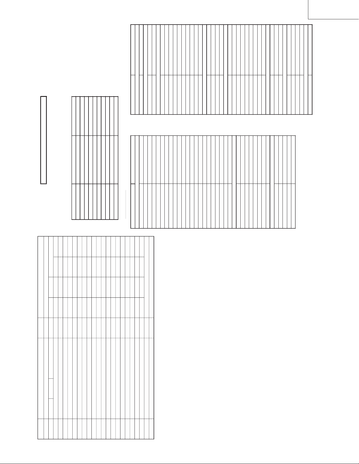
SREC/SRAC/SYI/STTM SREC-SCA (SKD)
R/C CODE
MCL 1 (R/C CODE 117h) MCL 2 (R/C CODE 169h)
TV-CH. CH-No. Fv (MHz) S-SYSTEM CH-No. Fv (MHz) S-SYSTEM
0SKIP OFF FREE 590.25 5.5 B/G
1E-2 48.25 5.5 B/G AU-0 46.25 5.5 B/G
2 E-4/B-3 62.25 5.5 B/G AU-2 64.25 5.5 B/G
3OIR-3 77.25 6.5 D/K AU-3 86.25 5.5 B/G
4E-5 175.25 5.5 B/G AU-4 95.25 5.5 B/G
5E-6/B-5 182.25 5.5 B/G AU-5A 138.25 5.5 B/G
6OIR-7 183.25 6.5 D/K AU-6 175.25 5.5 B/G
7OIR-8 191.25 6.5 D/K AU-7 182.25 5.5 B/G
8E-8/B-7 196.25 5.5 B/G AU-8 189.25 5.5 B/G
9J-9 199.25 4.5 M AU-9 196.25 5.5 B/G
10 E-10/B-9 210.25 5.5 B/G AU-10 209.25 5.5 B/G
11 E-12/B-1 224.25 5.5 B/G AU-11 216.25 5.5 B/G
12 E-21 471.25 5.5 B/G SKIP OFF FREE
13 I-23 487.25 6.0 I SKIP OFF FREE
14 E-25 503.25 5.5 B/G SKIP OFF FREE
15 E-34 575.25 5.5 B/G SKIP OFF FREE
16 E-35 583.25 5.5 B/G SKIP OFF FREE
17 E-37 599.25 5.5 B/G SKIP OFF FREE
18 J-38 621.25 4.5 M SKIP OFF FREE
19 OIR-42 639.25 6.5 D/K SKIP OFF FREE
20 B-50 703.25 5.5 B/G SKIP OFF FREE
21 I-54 735.25 6.0 I SKIP OFF FREE
22 E-58 767.25 5.5 B/G SKIP OFF FREE
23 E-64 815.25 5.5 B/G SKIP OFF FREE
24 I-69 855.25 6.0 I SKIP OFF FREE
25 E-69 855.25 5.5 B/G SKIP OFF FREE
26 US-2 55.25 4.5 M SKIP OFF FREE
27 A-6 83.25 4.5 M SKIP OFF FREE
28 JA-6 183.25 4.5 M WE-28 527.25 5.5 B/G
29 JA-8 193.25 4.5 M SKIP OFF FREE
30 JA-12 217.25 4.5 M SKIP OFF FREE
31 US-14 471.25 4.5 M SKIP OFF FREE
32 JA-14 477.25 4.5 M SKIP OFF FREE
33 JA-50 693.25 4.5 M SKIP OFF FREE
34 US-83 885.25 4.5 M SKIP OFF FREE
35 S-2 112.25 5.5 B/G SKIP OFF FREE
36 S-10 168.25 5.5 B/G SKIP OFF FREE
37 SKIP OFF FREE 590.25 5.5 B/G
38 S-20 294.25 5.5 B/G SKIP OFF FREE
39 S-41 463.25 5.5 B/G SKIP OFF FREE
40 SKIP OFF FREE SKIP OFF FREE
41 B-43 647.25 5.5 B/G E-2 48.25 5.5 B/G
42 B-45 663.25 5.5 B/G WE-4 62.25 5.5 B/G
43 B-47 679.25 5.5 B/G OI-3 77.25 6.5 D/K
44 E-5 174.95 5.5 B/G E-5 175.25 5.5 B/G
45 E-5 175.55 5.5 B/G OIR-7 183.25 6.5 D/K
46 SKIP OFF FREE OIR-8 191.25 6.5 D/K
47 SKIP OFF FREE E-10 210.25 5.5 B/G
48 SKIP OFF FREE E-12 224.25 5.5 B/G
49 SKIP OFF FREE I-23 487.25 6.0 I
50 SKIP OFF FREE WE-25 503.25 5.5 B/G
51 SKIP OFF FREE E-34 575.25 5.5 B/G
INITIAL SETTING
(1) Execute MCL 1/2 key to set the following data in EEPROM.