Sharp 32HW-57EDE User manual

1
32HW-57E
CONTENTS
SHARP CORPORATION
PAL
B/G, I
/ SECAM
L/L’, B/G, D/K
SYSTEM COLOUR TELEVISION
SEJB32HW57E00
SERVICE MANUAL
In the interests o user sa ety (required by sa ety
regulations in some countries) the set should restored
to its original condition and only parts identical to
those speci ied should be used.
Issued: 6th Sept 2001
This document has been published to
be used or a ter sales service only.
DA-100W CHASSIS
ELECTRICAL SPECIFICATIONS......................3
IMPORTANT SERVICING NOTES....................4
ADJUSTMENTS PROCEDURES......................5
LED FLASHING CODES..................................10
PRINTED WIRING BOARDS............................11
COMPONENT LOCATION TABLES.................19
SCHEMATIC DIAGRAMS.................................26
BLOCK DIAGRAM............................................37
PARTS LISTING...............................................38
PACKING OF THE SET & ACCESSORIES.....49
CONTROLS &TERMINALS..............................50
MODEL
32HW-57E
DE/ES/IT/SE
RTV servis Horvat
Tel: ++385-31-856-842
Tel/fax: ++385-31-856-139
Mob: 098-788-319
www.rtv-horvat-d .hr

3
32HW-57E
ELECTRICAL SPECIFICATIONS
•White Level
Set brightness control to get total picture tube cathode current o 600 milliammeter under no signal
condition. Maximum necessary correction o each picture tube cathode current to get 8550 de-
grees K+1 MPCD screen temperature should not exceed 15% o its original value.
X=0 290 Y=0 300
WARNING
The chassis in this receiver is partially hot. Use an isolation trans ormer between the line cord plug
and power receptacle, when servicing this chassis.
To prevent electric shock, do not remove cover. No user-serviceable parts inside. Re er servicing to
quali ied service personnel.
Speci ications are subject to change without prior notice.
•Picture Intermediate requency
L’......................................................33.9MHz
L, B/G, D/K, I...............................38.9MHz
•Sound Carrier Trap
L’..................................................40.4MHz
L, D/K...........................................32.4MHz
B/G..............................................33.4MHz
I....................................................32.9MHz
•Adjacent Sound Carrier Trap
L’..................................................32.4MHz
L, D/K, B/G..................................40.4MHz
I....................................................40.9MHz
•Adjacent Picture Carrier Trap
L’..........................................................41.9MHz
L, D/K, I........................................30.9MHz
B/G..............................................31.9MHz
•Aerial Input Impedance
VHF/UHF ................. 75 ohm Unbalanced
•Tuning Ranges ..... 45.75MHz thru 855.25 MHz
VHF: E2-E12 CH / F2-F10 CH, IR A -IR J CH
S1 - S41 CH (HIPERBAND)
UHF: E-21- E69 CH, I21-I69 CH
•Power Input ...................... 220V-240 Volts AC 50Hz
•Power Consumption
Normal Operation .................................115W
Stand-by Operation ...............................1.3W
•Audio Power Output Rating (MPO) / Impedance
Internal Le t Speaker ...................... 10W, 7Ω
Internal Right Speaker .................... 10W, 7Ω
•Speakers
Le t / Right ...............................12W, 6 x 12cm
•Convergence
Static (Centre) ........ between any two colours
Dynamic ..................... a ter static equals zero
•Focus ....................... High Bi-Potential Electrostatic
•Sweep De lection ............................... Magnetic
MODEL DESTINATION (Operation Manual languages)
32HW-57EDE: Dutch, French, German and Italian.
32HW-57EES: Portuguese and Spanish.
32HW-57EIT: Italian.
32HW-57ESE: Danish, English, Finnish, Norwegian and Swedish.

4
32HW-57E
IMPORTANT SERVICING NOTES
Only qualified se vice pe sonnel a e allowed to ca y out maintenance and epai of this eceive .
SERVICING OF HIGH VOLTAGE SYSTEM AND CRT
It is impo tant that the static cha ge is emoved f om the high voltage system when ca ying out wo k
on the eceive . This can be achieved by connecting a 10K esisto (with a suitably insulated lead) f om
the CRT cavity connecto to the CRT g ound tag. This must be ca ied out with the AC supply discon-
nected f om the eceive .
Note the following:
• The CRT in this eceive employs Integ al Implosion P otection.
• If the CRT has to be changed it MUST be eplaced with the co ect type fo continued safe
wo king
• DO NOT lift the CRT by its neck.
• When handing the CRT, ensu e that shatte p oof goggles a e wo n.
• Ensu e that the CRT is discha ge befo e handling.
X-RAY
This eceive is designed to keep any x- ay emission to an absolute minimum. Some fault conditions
and se vicing p ocedu es may p oduce potentially haza dous x- ay adiation levels. This is a p oblem
when in close p oximity to the eceive fo long pe iods of time. To educe any isks associated with
this, please obse ve the following p ecautions:
1. When unde taking any se vicing on this chassis, DO NOT inc ease the EHT to mo e than 33 KV,
(at a instantaneous beam cu ent of 2000µΑ).
2. Ensu e that du ing no mal ope ation the EHT does not exceed 30KV±1.5KV (at a beam cu ent of
1500µΑ). This level has been p eset in the facto y. Always check that this level has not been ex-
ceeded afte ca ying out any epai on the eceive ..
3. DO NOT eplace the CRT with any othe type than that specified in the pa ts listing as this may
cause excessive x- ay adiation.
BEFORE RETURNING THE RECEIVER TO THE CUSTOMER
In addition to the above checks, the following should also be ca ied out befo e etu ning the eceive
to the custome .
1. Inspect all the leads to ensu e that they a e d essed co ectly and that they a e not obst ucted o
pinched by any othe pa ts.
2. Ensu e that all p otective devices a e in good condition. These will include nonmetallic cont ol
knobs, insulating fish pape s, cabinets backs, compa tment cove s o shields, mechanical insulato s,
etc.

5
32HW-57E
ADJUSTMENT PROCEDURES
All adjustments to this chassis, except or ocus, are carried out in the service mode.
••
••
• SERVICE MODE
The service mode is provided to enable the engineer to correctly set up the receiver to the CRT itted in the set.
Note that these adjustments may vary rom one receiver to another.
To enter the service mode, carry out the ollowing procedure.
1. Connect a test pattern to the antenna terminal.
2. Tune the receiver to this signal.
3. Turn the receiver o using the mains switch.
4. Press volume down and channel up buttons on the
ront o the receiver at the same time.
5. Keeping these buttons pressed, turn the mains on.
6. When the set starts up it will be in service mode.
7. Release the two buttons.
••
••
• Use the channel up and down buttons to move between the options.
••
••
• Use the volume control buttons to change the data.
••
••
• To store the data, use the stand-by button on the remote control.
••
••
• To exit the service mode, turn the receiver o using the mains switch.
When the service mode is entered the ollowing On Screen Display appears
-SERVICE SOFTWARE AND HEXADECIMAL COUNTER DISPLAY:
SW ON XXXX SW OFF XXXX HOURS ON XXXX
The igures displayed in the XXXX locations are hexadecimal representations o the number o times that particular
unction has been executed. For example i the hexadecimal number displayed a ter SW ON was 0E4A, this would
correspond to the receiver being turned on 3658 times.
Adjustment menu:
The ollowing adjustments can be carried out in the service mode.
• Horizontal Shi t
• East West Width
• Pin Phase
• Pin Amp
• Upper Corner Correction
• Vertical Linearity
• Vertical Angle
• Vertical Bow
• Vertical Amplitude
• S Correction
• Vertical Shi t
• Red Gain
• Green Gain
• Blue Gain
• Red Cut O
• Green Cut O
• Blue Cut O
• Alter NVM Page
• Alter NVM Position
• Alter NVM Value
• Teletext Mix Mode Contrast
• Teletext Contrast
• OSD Contrast
• DVCO Adjustment (Only PAL)
• DVCO Adjustment (Only NTSC)
• Luma Croma delay
• AGC Adjustment
• AFT Adjustment
• AFT Adjustment or L’
• OPC Value (Not available in this model)
• Auto Installation On/O
Geometry Adjustments
All geometry adjustments are based on an internally generated test pattern as shown
in igure 1. When carrying out any o the above geometry adjustments, use the inter-
nally generated test pattern or guidance.
Note that the receiver should be set to FULL MODE be ore carrying out any geom-
etry adjustments. This can be achieved by pressing the widescreen mode button on
the remote control until FULL MODE appears on the OSD. This can only be done
out o the service mode.
CH
4
5
Fig.1

6
32HW-57E
Horizontal
• Horizontal Shi t
• E-W Width
• Pin Phase
• Pin Amp
• Upper Corner Amplitude
• Lower Corner Symmetry
• Extreme Corner Symmetry
Vertical
• Vertical Amplitude
• S Correction
• Vertical Shi t
• Vertical Linearity
• Vertical angle
• Vertical bow
Just in case the TV set requires a ull geometries adjustment, please proceed irst with
Vertical according to the above order, and a ter that, adjust Horizontal according to the
above order.
Horizontal Shift
Adjust the horizontal shi t so that the picture is centred.
The e ect o this adjustment is shown in igure 2.
• When the volume up button is pressed, the picture moves to the le t.
• When the volume down button is pressed, the picture moves to the right.
• Press the stand-by button on the remote control to store.
E-W Width
Adjust the E-W Width so that 9% over-scan is achieved.
The e ect o this adjustment is shown in igure 3.
• When the volume up button is pressed, horizontal scanning increases.
• When the volume down button is pressed, horizontal scanning decreases.
• Press the stand-by button on the remote control to store.
Pin Phase
Adjust the Pin Phase so that the picture is symmetrical top and bottom.
The e ect o this adjustment is shown in igure 4.
• When the volume up button is pressed, side pincushion changes.
• When the volume down button is pressed, side pincushion changes.
• Press the stand-by button on the remote control to store.
Pin Amp
Adjust the Pin Amplitude so that the picture is centred.
The e ect o this adjustment is shown in igure 5.
• When the volume up button is pressed, side pincushion changes rom pincushion to
barrel shape.
• When the volume down button is pressed, side pincushion changes rom pincush-
ion to barrel shape.
• Press the stand-by button on the remote control to store.
Upper Corner Correction
Adjust the Upper Corner Correction so that the picture is centred.
The e ect o this adjustment is shown in igure 6.
• When the volume up button is pressed, side pincushion changes rom pincushion to
barrel shape.
• When the volume down button is pressed, side pincushion changes rom pincush-
ion to barrel shape.
• Press the stand-by button on the remote control to store.
Fig.2
Fig.3
Fig.4
Fig.5
Fig.6
The ollowing geometry adjustments can be carried out. Detailed instructions on how to execute these are given on
the ollowing pages

7
32HW-57E
Lower Corner Correction
Adjust the Lower Corner Correction so that the picture is centred.
The e ect o this adjustment is shown in igure 7.
• When the volume up button is pressed, side pincushion changes rom pincushion to
barrel shape.
• When the volume down button is pressed, side pincushion changes rom pincushion to
barrel shape.
• Press the stand-by button on the remote control to store.
Vertical Linearity
Adjust the Vertical Linearity so that the upper and lower parts o the picture are symmetrical.
The e ect o this adjustment is shown in igure 8.
• When the volume up button is pressed, the upper picture scanning decreases and the
lower picture scanning increases.
• When the volume down button is pressed, the upper picture scanning increases and the
lower picture scanning decreases.
• Press the stand-by button on the remote control to store.
Vertical Angle
Adjust the Vertical Amplitude so that the picture is centred.
The e ect o this adjustment is shown in igure 9
• When the volume up button is pressed, the vertical angle changes.
• When the volume down button is pressed, the vertical angle changes.
• Press the stand-by button on the remote control to store.
Vertical Bow
Adjust the Vertical Bow so that the picture is centred.
The e ect o this adjustment is shown in igure 10
• When the volume up button is pressed, the vertical bow changes to right.
• When the volume down button is pressed, the vertical bow changes to le t.
• Press the stand-by button on the remote control to store.
Vertical Amplitude
Adjust the Vertical Amplitude so that the picture is over-scanned.
The e ect o this adjustment is shown in igure 11.
• When the volume up button is pressed, the vertical size o the picture increases.
• When the volume down button is pressed, the vertical size o the picture decreases.
• Press the stand-by button on the remote control to store.
S Correction
Adjust the S Correction so that the picture symmetrical between the top, centre and bottom.
The e ect o this adjustment is shown in igure 12.
• When the volume up button is pressed, the top and bottom scanning increases and the
centre scanning decreases.
Fig.8
Fig.12
Fig.11
Fig.7
Fig.10
Fig.9

8
32HW-57E
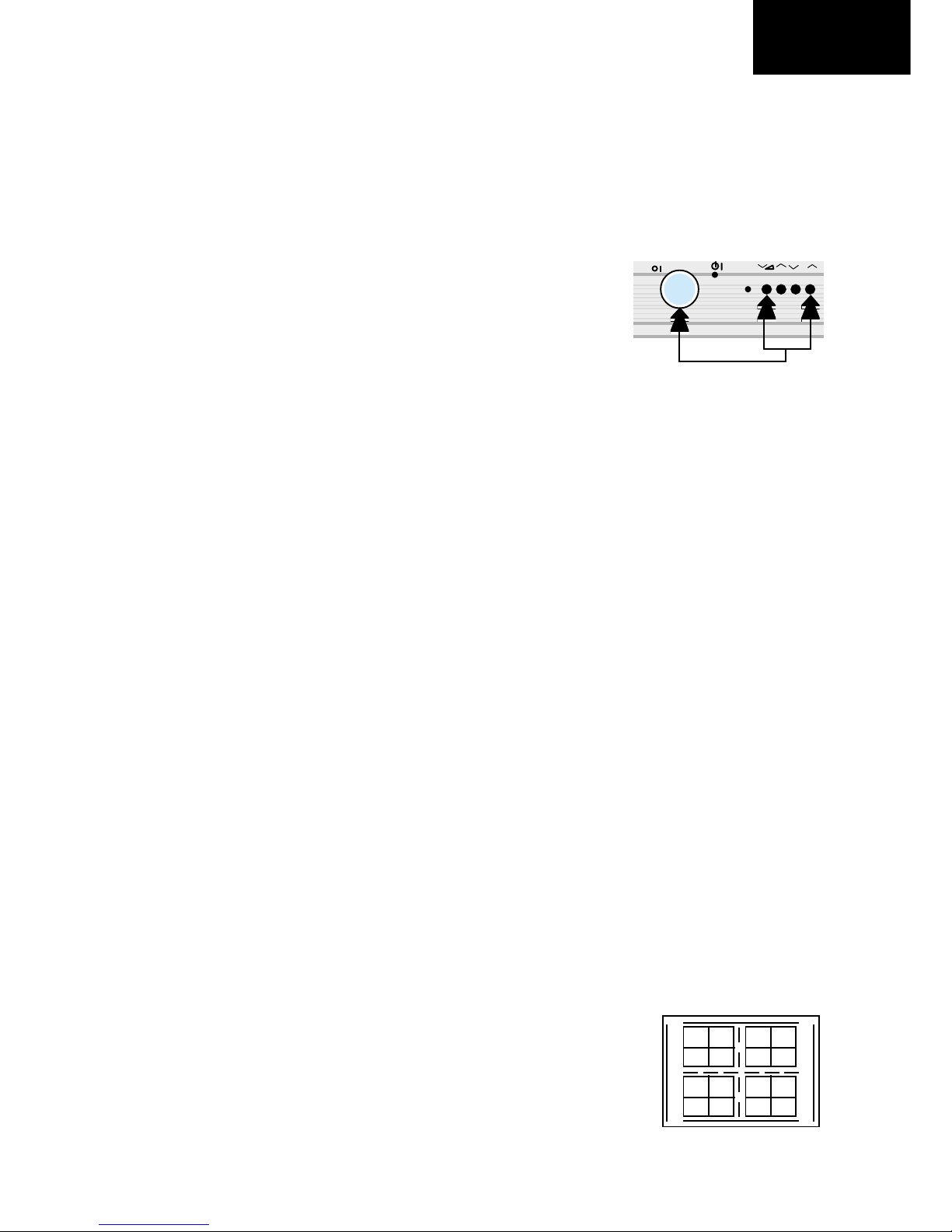
To increase press volume-up button and to decrease press
volume down button.
RED CUT OFF alte «X» coo dinate.
GREEN CUT OFF alte «Y» coo dinate.
BLUE CUT OFF alte «X» and «Y» coo dinates.
Changing NVM Data
To change the data contained within the Non Volatile
Memory, it is necessary to irst select the page the data is
stored in, then the position and inally to change the data
itsel . The procedure below outlines this process.
1. While on ALTER NVM PAGE, use the volume up/down
buttons to change this data (data is shown in hexadecimal
ormat).
2. Press the channel up button and ALTER NVM POSITION
appears, use the volume up/down buttons to change this
data (data is shown in hexadecimal ormat).
3. Press the channel up button and ALTER NVM VALUE
appears, use the volume up/down buttons to change this
data (data is shown in hexadecimal ormat).
4. Once this data has been set, press the standby button to
store.
5. I another NVM value has to be changed, use the channel
down button to select the page or position and repeat as
necessary.
Note:
DO NOT change any NVM data, unless you have been
advised to do so by a Sharp representative. I data is
incorrectly changed, serious damage may occur to the
receiver.
Colour Adjustments
The ollowing adjustments should only be carried out when
the CRT, IC801 or IC801 are replaced.
G2, Cut Off and Gain Adjustments
1 Follow the procedure below to set the G2
1.1 Tune the set to the output o a signal generator
(cross hatch pattern).
1.2 In the user menu, set contrast to 80/100 and
brightness to 40/100.
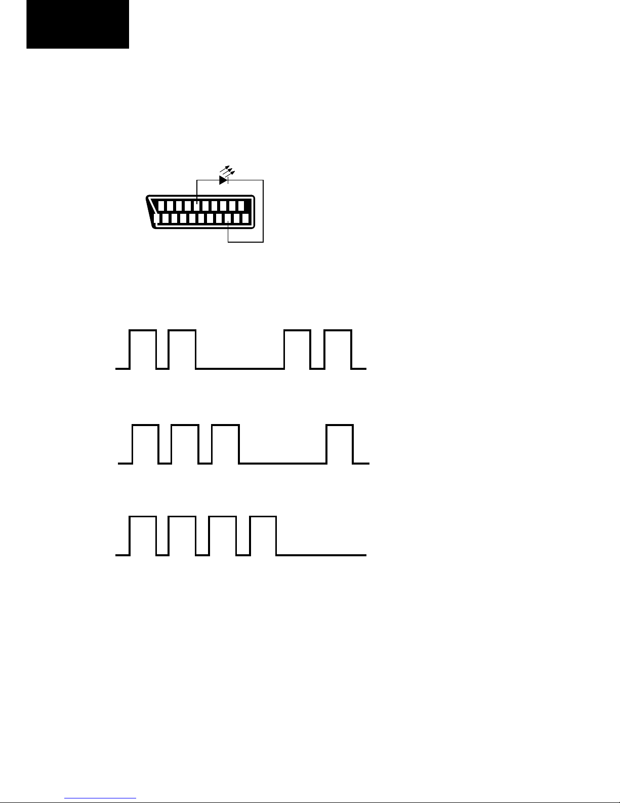
1.3 Connect the oscilloscope to the red cathode and
adjust G2 to read 155V on the sensor pulse as
in the drawing:
NOTE:
Oscilloscope should be adjusted or vertical TV ield trigger
and synchronized with video signal.
2 Follow the procedure below to set the Cut Off
2.1 Adjust G2.
2.2 Tune a white card.
2.3 Adjust colour to minimum.
2.4 Position colorimeter in the centre o screen.
2.5 Adjust brightness and contrast to obtain a lumi-
nance o ≈20 NITS.
2.6 Operate in Service Mode and select location RED
CUT OFF, GREEN CUT OFF and BLUE CUT
OFF, to obtain colour coordinates:
X=0.290 ± 0.015 Y=0.300 ± 0.015
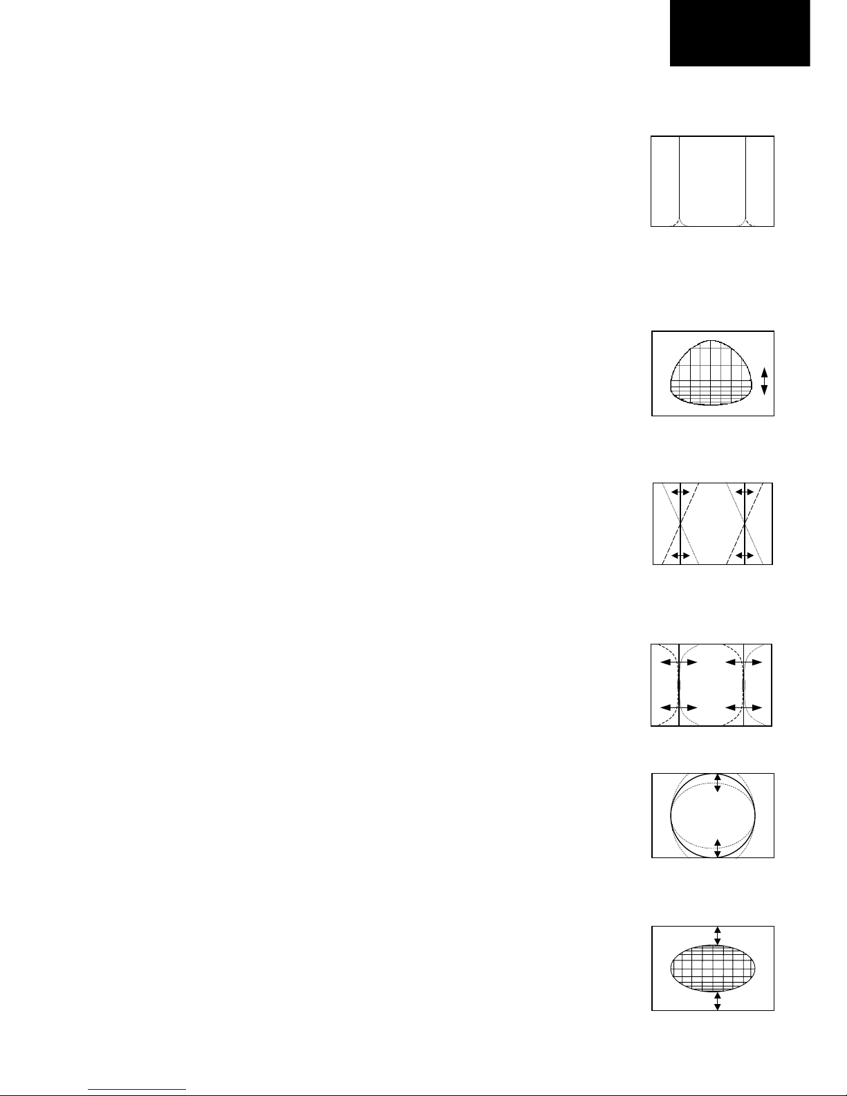
• When the volume down button is pressed the top and bottom scanning decreases and
the centre scanning increases.
• Press the stand-by button on the remote control to store.
Vertical Shift
Adjust the Vertical Shi t so that the picture is centred.
The e ect o this adjustment is shown in igure 13.
• When the volume up button is pressed, the picture moves down.
• When the volume down button is pressed, the picture moves up.
• Press the stand-by button on the remote control to store.
155 V
CH1 gnd
Fig.13

9
32HW-57E
Contrast Adjustments
Three types o contrast levels can be varied as listed below:
• TELETEXT MIX MODE CONTRAST
• TELETEXT CONTRAST
• OSD CONTRAST
Use the volume up/down buttons to adjust to a suitable level, then press the standby button to store.
DVCO Adjustment (PAL)
Carry out the DVCO Adjustment (PAL) as shown below:
1. Receive a Phillips pattern signal.
2. While in the DVCO ADJUSTMENT (PAL) menu, press the standby button.
3. The adjustment will be carried out automatically and stored.
DVCO Adjustment (NTSC)
No adjustment required.
Auto Installation On/Off
To return the receiver to the original Auto Installation mode, using the volume up or down button, set the Auto Installation
On/O to On. This setting is automatically stored and when the receiver is turned on the next time it will start up in Auto
Installation mode.
AGC Adjustment
To correctly align the Automatic Gain Control, ollow the procedure outlined below:
1. Tune the set into a pattern generator on CH10.
2. Adjust the signal strength o the pattern generator to 57uV
3. Enter the service mode.
4. Enter the AGC Adjustment menu.
5. Press the standby button on the remote control.
6. The adjustment will be carried out and stored automatically.
AFT Adjustment (BG-I, SECAM L)
To correctly align the Automatic Fine Tune, ollow the procedure outlined below:
1. Tune the set into a pattern generator on CH69.
2. Enter the service mode.
3. Enter the AFT Adjustment menu.
4. Press the standby button on the remote control.
5. The adjustment will be carried out and stored automatically.
AFT Adjustment (SECAM L’)
To correctly align the Automatic Fine Tune, ollow the procedure outlined below:
1. Tune the set into a pattern generator on CH04.
2. Enter the service mode.
3. Enter the AFT Adjustment menu.
4. Press the standby button on the remote control.
5. The adjustment will be carried out and stored automatically.

10
32HW-57E
LED FLASHING CODES
This model is not provided with stereo led, so to let “ lashing codes” or IC ailures detection when the TV set does not
work, we have answered with the next solution:
• The detection o ailure will be made with an external LED.
• The output o the lashing code will be via AV1 (pin 12).
• Insert a generic led diode between pin 12 and ground (i.e. pin 5, 13 or 21) as shows the below picture.
Follow the sequence according to the in ormation below, as a guide to ault inding.
1. Unable to read or write into NVM: 66% ON, 33% OFF twice and OFF or a second.
2. MSP failure: 66% ON, 33% OFF or three times and OFF or a second.
3. VPC failure: 66% ON, 33% OFF or our times and OFF or a second.
4. SDA failure: 66% ON, 33% OFF or ive times and OFF or a second.
5. DDP failure: 66% ON, 33% OFF or six times and OFF or a second.
NOTE:
I you want to check that the system is working, open resistor R307 to avoid I2C comunication with MSP. The TV set will
lash three times and OFF or a second, showing MSP ailure.
Then the system is working properly.
On O
On O
On O
21
21 19 17 15 13 11 9 7 5 3 1
20 18 16 14 12 10 8 6 4 2

16
32HW-57E
CRT MODULE UNIT PRINTED WIRING BOARD (F7269N3) Component side
+
C895
C891
C
Q858
E
E
Q857
C
JF5
JF7
C
Q861
E
R885
E
Q860
C
R874
R882
J10
R881 C865
R866
R886
JF2
C5405
R5447
1
L1603
(RT)
E
Q5415
B
1
(Q)
R884
+
C5426
R5449
R5448
C5425
+
D863
R892
R894
J20 R1624
R1617 D1607
C1610 R1618
R1616
R1615
C1611
R871
L864
J11
R5437
C5418
+
D5411
J25
C5419
+
C850
+
R5436
E
Q5414 B
(SVM)
(H)
(K)
1
3
R5444
C5422
R5421
R5424
D5405
R5442
C5411
D5403
R5419
C5409
R5418R5417
C5408
R5416
R5445
R5443
C893
R5440
R862
R865
D864
C892
R5439
C855
C851
+
D869
D868
C863
+
.
1(B)
R1801
4
12
11
10
9
8
7
6
5
SC861
C884
K7269BM F7269BMN3
ESPA¥A
L3
L2
(G2)
+
C853
R851
C883
C882
R861
J13
D852
R856
C877
91 IC852
R859
R853
R852
R888
R880C880
R872
C871
J1
J8
R863
J9
R850
C881
91 IC850
R858
R860
C861
J7
FB850
J12
J3
1
8
C5417
R5415
FB851
R883
R875
IC851
1
9
C874
R895
J6
R868
C862
Q5407
BE
E
Q854
C
C885
C852
C856
C857
SG863
EB
Q5408
J4
C859
C889
R864
R869
R867
R870
R873
E
Q856
C
D862
SG860
J14
R897
FB852
J18
E
Q859
C
J17
B
Q851
E
D851
+
C5414
D865
D866
D867
C
Q1604
E
+
C1613
(MO)
R1622
C1609
+
R1621
1
IC1601
R854
R893
SG864
C869
SG861
R891
J21
D870
JF1
C894
+
J23
SG865
R5441
C868
+
J19
D5404
C5421
E
Q5410
C
E
Q5412
C
C
Q5411 E
D5408
C890
C5407
E
Q5405
C
D5409
L863
J24
R887
D861
R889
R5446
C5424
C5420
E
Q5406
C
R5425
D5410
C5410
R5420
SG862
J15
D871
R1619
R876
R1620
C1608
+
J5
C
Q1603
E
R1623
JF4
C887
+
JF6
C854
R857
C
Q852
E
C
Q853
E
R855
E
Q855
C
R5438
JF3
C888
R5427
R5435
R5432
R5434
C5416
R5433
R5431
JF8
C1612
+
J16 C1614
11
12
13
1
2
3
4
5
6
7
8
9
10
Y
X
010 11 12 13 14 15 16 17123456789
DIGITAL MODULE UNIT PRINTED WIRING BOARD (F7295NOA) Component side
Y
X
11
12
13
14
15
16
1
2
3
4
5
6
7
8
9
10
0
654321
C6083
C6009
+
C6014
+
+
C6016
X1003
C6079
+
C6065
IC6005
B
Q6003
E
R6050
1(KA)
8
112
Y(B)
Y(A)
6121
112
Y(C)
(RGB) 41
+
C6035
C6030
+
+
C6027
IC6001
124
25
65
64 41
40
C6034
+
IC6002
48
32 16
1
X6002
61
44
43 27
10
9
IC6003
C6021
+
+
C6023
X6001
1
K7295BM
ESPA¥A
F7295BMN0
C6069
+
A

17
32HW-57E
CRT MODULE UNIT PRINTED WIRING BOARD (F7269N3) Copper side
+
C895 C891
Q858
C
EEC
Q857
JF5
JF7
Q861
C
E
R885
E
C
Q860
R874
R882
J10
R881
C865
R866
R886
JF2
C5405
R5447
L1603
Q5415
E
B
1(Q)
R884
+
C5426
R5449
R5448
C5425
+
D863
R892
R894
J20
R1624
R1617 D1607
C1610
R1618
R1616
R1615
C1611
R871
L864
J11
R5437
C5418
+
D5411
J25
C5419
+
C850
+
R5436
Q5414
E
B
(K)
(H)
(SVM)
1
3
R5444
C5422
R5421
R5424
D5405
R5442
C5411
D5403
R5419
C5409
R5418
R5417
C5408
R5416
R5445 R5443
C893
R5440
R862
R865
D864
C892
R5439
C855
C851
+
D869
D868
C863
+
.
(RT)
F7269BMN3
(B)
R1801
SC861
12
11
10
9
8
7
6
5
4
C884
+
C853
R851
C883
C882
R861
J13
D852
R856
C877
IC852 19
R859
R853
R852
R888
R880
C880
R872
C871
J1
J8
R863
J9
R850
C881
IC850 19
R858
R860
C861
J7
FB850
J12
J3
1
8
C5417
R5415
FB851
R883 R875
91
IC851
C874 R895
J6
R868
C862
Q5407
B
E
E
C
Q854
C885
C852
C856
C857
SG863
E
B Q5408
J4
C859
C889
R864
R869
R867
R870
R873
E
C
Q856
D862
SG860
J14
R897
FB852
J18
E
C
Q859
J17
BE
Q851
D851
C5414
D865
D866
D867
Q1604
C
E
+
C1613
(MO)
R1622
C1609
+
R1621
8
41
IC1601
R854
R893
SG864
C869
SG861
R891
J21
D870
JF1
C894
+
J23
SG865
R5441
C868
+
J19
D5404
C5421
EC
Q5410
EC
Q5412
Q5411
C
E
D5408
C890
C5407
EC
Q5405
D5409
L863
J24
R887
D861
R889
R5446
C5424
C5420
EC
Q5406
R5425
D5410
C5410
R5420
SG862
J15
D871
R1619
R876
R1620
C1608
+
J5
Q1603 C
E
R1623
JF4
C887
+
JF6
C854 R857
Q852
C
E
Q853
C
E
R855
E
C
Q855
R5438
JF3
C888
R5427
R5435
R5432
R5434
C5416
R5433
R5431
JF8
+
J16
C1614
Y
11
12
13
1
2
3
4
5
6
7
8
9
10
X
0
10 9876 543 2117 16 15 14 13 12 11
X
Y
11
12
13
14
15
16
1
2
3
4
5
6
7
8
9
10
0123456
C6236
C6202
C6201
C6203
C6204
C6205
C6306
C6212
C6213
D6003
KK
D6004
C6083
R6039
R6075
+
JF2
R6118
R6095
R6081
R6009
R6010
R6018
R6016
R6014
R6019
R6012
R6017
R6015
R6013
R6011
R6008
R6080
R6087
C6014
++
C6016
C6011 JF1
FB6210
FB6211
FB6212
L6012
C6066
C6044
C6045
R6307
D6006
K
R6003
R6001
R6002
L6017
L6003
C6006
C6007
C6001
C6004
C6010
C6028
C6029
C6037
C6026
R6128
L6007
R6035
C6024 C6072 C6073
R6129
Q6026
D6015
K
R6125
Q6025D6014
K
R6041
C6064
R6042
R6127
R6068
X1003
C6079
R6086
C6078
R6107
R6105
R6103
D6008
K
R6104
Q6024
C6110
R6106
Q6023
R6101
C6109
C6081
D6010
K
Q6022
R6100
R6088
R6097
R6096 R6098
R6099
C6074
D6007
K
Q6021
+
C6065
C6060
C6061 C6046 C6039
C6053
C6230
IC6005
BE
Q6003
R6050
1
(KA)
8
1
Y(C)
(RGB)
41
L6010
+
C6035
C6030
+
+
C6027
C6034
+
X6002
R6021
R6023
R6025
R6027
R6029
R6031
R6092
R6083
R6084
R6020
R6022
R6024
R6026
R6028
R6030
R6082
C6229
C6228
C6234
C6231
C6233
C6232
R6049
R6037
C6012C6048
C6021
+
+
C6023
L6006 C6042
C6049
C6013
Q6006
R6117
C6041
C6052
C6051
C6038
C6008
X6001
C6032
R6051
R6054
C6068 R6052
L6001 L6009
IC6006
1
C6067
K
D6005
R6090
L6015
L6014
FB6208
FB6206
FB6205
FB6207
R6102
C6033
L6002
C6226
C6225
C6224
C6223
C6222
C6221
C6220
C6227 C6218
C6219
R6038
Q6008
R6069
R6089
D6013
K
R6124
R6007
C6215
C6020
C6216
C6217
C6019
C6018
R6006
C6017
C6015
R6123
R6048
C6022
L6005
K D6002
R6036
KD6001
C6036
C6031
C6025
C6002
C6005
L6004
R6005
C6009
C6069
+
JF5
R6043
C6082
R6032
R6040
F7295BMN0 A
C6054
C6057
C6043
C6040C6047
C6050
C6062
C6070
R6126
R6073
C6059
R6072
C6058
R6071
C6056
R6074
C6055
C6063
R6004
C6206
C6207
C6209
C6214
C6211
L6008
L6013
C6208
Q6027
R6130
JF3
C6084
C6085
DIGITAL MODULE UNIT PRINTED WIRING BOARD (F7295NOA) Copper side

18
32HW-57E
DYNAMIC FOCUS AND PFC (F7271N4) UNIT PRINTED WIRING BOARDS
0123456 7
22
23
24
25
17
18
19
20
21
11
12
13
14
15
16
1
2
3
4
5
6
7
8
9
10
X
Y765Å321
1
0
Y
X
22
23
24
25
17
18
19
20
21
11
12
13
14
15
16
2
3
4
5
6
7
8
9
10
Component Side
Copper Side

20
32HW-57E
MOTHER UNIT (F7293N7A) PWB COMPONENT LOCATION TABLES
Component Side
5HI1R ;XP <XP
5
5
5
5
5
5
5
5
5
5
5
5
5
5
5
5
5
5
5
5
5
5
5
5
5
5
5
5
5
5
5
5
5
5
5
5
5
5
5
5
5
5
5
5
5
5
5$
5
5
5
5
5
5
5
5
5
5
5HI1R ;XP <XP
5
5
5
5
5
5
5
5
5
5
5
5
5
5
5
5
5
5
5
5
5
5
5
5
5()
5()$
5()
6
6
6
6
6
6)
6)
6)
7
7
7+
;
;
;
;
5HI1R ;XP <XP
-
-
-
-
-
-
-
-
-
-
-
-
-
-
-
-
-
-
-
-
-
-
-
-
-
-
-
-
-
-
-
-
-
-
-
-
-
-
-
-
-
-
-
-
-
-
-
-
-
-
-
-
-
-
-
-
-
5HI1R ;XP <XP
-
-
-
-
-
-
-
-
-
-
-
-
-
-
-
-
-
-
-
-
-
-
-
-
-
-
-
-
-
-
-
-
-
-
-
-
-
-
-
-
-
-
-
-
-
-
-
-
-
-
-)
-)
-)
-)
-)
-)
-)
5HI1R ;XP <XP
-)
-)
-)
-)
-)
-)
-)
-)
-)
-)
-)
-)
-)
-)
-)
-)
-)
-)
-)
-)
-)
-)
-)
-/
-/
-/
-/
-/
-/
-/
-/
-/
-/
-/
-/
-/
-/
-/
-/
-/
-/
-/
-/
-/
-/
-/
-/
-/
-/
-/
-/
-/
-/
-/
/
/
/
5HI1R ;XP <XP
/
/
/
/
/
/
/
/
/
/
/
/
/
/
/
/$
/
/$
/
/
/
/$
/
/
/
/$
/
/
/
/
/
/
/3
0
325
4
4
4
4
4
4
4$
4
4
4
5
5
5
5
5
5
5
5
5
5
5
5

21
32HW-57E
MOTHER UNIT (F7293N7A) PWB COMPONENT LOCATION TABLES
5HI1R ;XP <XP
&
&
&
&
&
&
&
&
&
&
&
&
&
&
&
&
&
&
&
&
&
&
&
&
&
&
&
&
&
&
&
&
&
&
&
&
&
&
&
&
&
'
'
'
'
'
'
'
'
'
'
'
'
'
'
'
'

22
32HW-57E
MOTHER UNIT (F7293N7A) PWB COMPONENT LOCATION TABLES
Copper Side
5HI1R ;XP <XP
-
-
-
-
-
-
-
-
-
-
-
-
-
-
-
-
-
-)
-)
-)
-)
-)
-)
-)
-)
-)
-)
-)
-)
-)
-)
-)
-)
-)
-)
-)
-)
-)
-)
-)
-)
-)
-)
-)
-)
-)
-)
-)
-)
-)
-)
-)
-)
-)
-)
-)
-)
5HI1R ;XP <XP
-)
-)
-)
/
/
/
/
/
4
4
4
4
4
4
4
4
4
4
4
4
4
4
4
4
4
4
4
4
4
4
4
4
4
4
4
4
4
4
4
4
4
4
4
4
4
4
4
4
4
4
4
4
4
4
4
4
4
5HI1R ;XP <XP
4
4
4
4
4
4
4
4
5
5
5
5
5
5
5
5
5
5
5
5
5
5
5
5
5
5
5
5
5
5
5
5
5
5
5
5
5
5
5
5
5
5
5
5
5
5
5
5
5
5
5
5
5
5
5
5
5
5HI1R ;XP <XP
5
5
5
5
5
5
5
5
5
5
5
5
5
5
5
5
5
5
5
5
5
5
5
5
5
5
5
5
5
5
5
5
5
5
5
5
5
5
5
5
5
5
5
5
5
5
5
5
5
5
5
5
5
5
5
5
5
5HI1R ;XP <XP
5
5
5
5
5
5
5
5
5
5
5
5
5
5
5
5
5
5
5
5
5
5
5
5
5
5
5
5
5
5
5
5
5
5
5
5
5
5
5
5
5
5
5
5
5
5
5
5
5
5
5
5
5
5
5
5
5
5HI1R ;XP <XP
5
5
5
5
5
5
5
5
5
5
5
5
5
5
5
5
5
5
5
5
5
5
5
5
5
5
5
5
5
5
5
5
5
5
5
5
5
5
5
5
5
5
5
5
5
5
5
5
5
5
5
5
5
5
5
5
5

23
32HW-57E
DINAMIC FOCUS AND PFC
UNIT (F7271N4) PWB
COMPONENT LOCATION
TABLES:
Component side:
MOTHER UNIT (F7293N7A) PWB
COMPONENT LOCATION TABLES
Copper Side
5HI1R ;XP <XP
5
5
5
5
5
5
5
5
5
5
5
5
5
5
5
5
5
5
5
5
5
5
5
5
5
5
5
5
5
5
5
5
5
5
5
5
5
5
5
5

24
32HW-57E
Ref No Xum Yum
JF3 25654 97028
JF4 10414 44958
JF5 25654 74930
JF6 10414 42418
JF7 28956 31242
JF8 150114 15240
L1603 66548 53848
L5 71628 38354
L863 102362 105918
L864 124968 55118
P5401 154432 76962
P661 7620 73152
P662 108204 115570
Q1603 116840 10160
Q1604 127508 10668
Q5405 139954 43942
Q5406 150114 43942
Q5407 128905 97790
Q5408 140970 68249
Q5410 150114 11176
Q5411 139954 27940
Q5412 150114 27940
Q5414 118364 94488
Q5415 76454 16002
Q851 33274 7620
Q852 22352 81534
Q853 29464 81534
Q854 53340 94284
Q855 37592 81534
Q856 15494 112268
Q857 25654 104902
Q858 34544 102870
Q859 8382 31750
Q860 19050 30734
Q861 26162 30988
R1615 117094 24130
R1616 117602 26670
R1617 124714 25146
R1618 117602 29210
R1619 78740 34036
R1620 70104 29464
R1621 94996 15240
R1622 133350 15494
R1623 118872 14732
R1624 120142 18542
R1801 15240 65531
R5415 125984 98298
R5416 136906 59182
R5417 141986 59182
R5418 144526 59182
R5419 149606 59182
R5420 130555 108458
R5421 136906 83312
R5424 148082 87630
R5425 125476 116332
R5427 151384 40640
R5431 150114 17780
Ref No Xum Yum
R5432 151384 35560
R5433 150114 20320
R5434 151384 33020
R5435 151384 38100
R5436 120650 88646
R5437 121158 74930
R5438 25654 94488
R5439 31750 112268
R5440 34544 41910
R5441 100330 75946
R5442 139954 49022
R5443 139954 52578
R5444 150114 49022
R5445 150114 52578
R5446 153924 94234
R5447 156972 17526
R5448 81280 20574
R5449 74930 23114
R850 50546 69342
R851 78740 102108
R852 60198 31750
R853 36322 15748
R854 18288 91440
R855 33020 81534
R856 39878 13970
R857 25654 88900
R858 37338 68580
R859 33782 15748
R860 34798 68580
R861 64262 102108
R862 27686 44196
R863 32258 68580
R864 23114 112268
R865 27686 40640
R866 41910 31750
R867 37338 112268
R868 51308 112776
R869 25654 112268
R870 39878 112268
R871 119126 38100
R872 33528 52578
R873 42418 112268
R874 14986 31750
R875 65531 115570
R876 49784 10922
R880 45466 50038
R881 35814 31750
R882 12446 31750
R883 85090 116332
R884 55118 14478
R885 22352 30734
R886 44450 31750
R887 58166 72898
R888 65531 64008
R889 82042 100330
R891 86360 85344
R892 66802 31496
Ref No Xum Yum
(B) 136906 10922
(MO) 93726 10922
(Q) 71374 11176
(RT) 61214 49784
C1608 75438 29718
C1609 133350 19304
C1610 107188 30226
C1611 116586 21336
C1612 90170 23876
C1613 106426 10414
C1614 96520 21590
C5405 156972 26924
C5407 139954 40132
C5408 139446 59182
C5409 147066 59182
C5410 122174 112268
C5411 152146 59182
C5414 152146 112014
C5416 150114 22860
C5417 140716 94234
C5418 128270 77470
C5419 120396 84582
C5420 141478 112014
C5421 146050 81026
C5422 154686 59182
C5424 149352 100076
C5425 80772 11430
C5426 67056 17272
C850 113792 76962
C851 17272 101600
C852 20320 21590
C853 14986 11430
C854 36576 88900
C855 28702 112268
C856 16510 21590
C857 12700 21590
C859 10160 112268
C861 29718 68580
C862 51308 115824
C863 55626 88392
C865 38862 31750
C868 102362 87884
C869 76200 80010
C871 30226 52578
C874 58674 102108
C877 43434 13462
C880 43434 54356
C881 47244 69342
C882 72136 102108
C883 75438 102108
C884 54864 18796
C885 57150 31750
C887 19558 42672
C888 25654 100584
C889 19812 112268
C890 139954 37592
C891 36576 94488
Ref No Xum Yum
C892 34544 112268
C893 37846 41656
C894 94996 70866
C895 76454 91440
D1607 127254 25146
D5403 157226 59182
D5404 135636 104394
D5405 143764 74676
D5408 139954 32512
D5409 139954 35052
D5410 122174 109220
D5411 117602 99314
D851 29210 15748
D852 24384 8382
D861 54102 72898
D862 92456 99060
D863 63500 33274
D864 27686 38100
D865 45720 46736
D866 67818 102108
D867 49530 31750
D868 50038 83312
D869 47498 83312
D870 104140 73406
D871 84328 11938
FB850 43688 73660
FB851 92202 112776
FB852 53340 37084
IC1601 103378 22606
IC850 37338 60706
IC851 69596 110236
IC852 47498 23622
J1 25654 52324
J10 33274 31242
J11 118364 53848
J12 15240 69342
J13 61468 102108
J14 45720 42672
J15 68834 7874
J16 87884 18288
J17 9906 21590
J18 8890 52324
J19 106680 97536
J20 109982 22606
J21 104140 70866
J23 93218 95758
J24 102362 104648
J25 133604 24384
J3 15240 71882
J4 15240 62865
J5 52324 7112
J6 52832 102108
J7 27178 68580
J8 23114 52324
J9 61214 82042
JF1 101600 78486
JF2 10922 94488
CRT UNIT (F7269N3) PWB COMPONENT LOCATION TABLES:
Component Side
Ref No Xum Yum
R893 73152 87884
R894 64516 43434
R895 55626 102108
R897 45720 39370
REF1 44450 1524
REF4 8382 -2794
SC861 87299 54914
SG860 68580 69088
SG861 81280 80772
SG862 76708 40132
SG863 71120 54279
SG864 69342 75946
SG865 91694 81280
Copper Side
No parts

25
32HW-57E
DIGITAL MODULE UNIT (F7295N0A) PWB COMPONENT LOCATION TABLES
Comp Side Copper Side
Ref No Xmm Ymm
(KA) 115620 52527
(RGB) 138938 52527
C6009 69596 29718
C6014 148082 52578
C6016 147574 43434
C6021 111760 24384
C6023 136144 17780
C6027 18796 30734
C6030 18796 39624
C6034 31750 51562
C6035 13208 45212
C6065 36576 24130
C6069 11430 52832
C6079 88900 20574
C6083 148844 20320
CR5 5842 -3023
IC6002 83058 37846
IC6003 131063 33528
IC6005 7620 45212
Q6003 7620 36576
R6050 7620 31750
REF1 48260 21590
X1003 125222 16510
X6001 21336 51816
X6002 79756 52324
Y(A) 23495 8686
Y(B) 75768 8686
Y(C) 125730 8686
Ref No Xmm Ymm
C6001 43180 45466
C6002 16764 45212
C6004 47244 39878
C6005 16764 43180
C6006 38100 47498
C6007 38100 45466
C6008 25400 34798
C6010 48260 35814
C6011 74930 37338
C6012 79502 30480
C6013 90932 42418
C6015 141732 45466
C6017 141986 41910
C6018 140462 48768
C6019 138684 48768
C6020 133350 48768
C6022 117856 36576
C6024 136144 19304
C6025 16764 47244
C6026 48260 33782
C6028 29464 30226
C6029 25400 38608
C6031 18796 49276
C6032 26416 49276
C6033 31750 50038
C6036 26162 44704
C6037 48260 31750
C6038 30734 21590
C6039 10414 22860
C6040 12192 22860
C6041 84582 44704
C6042 74422 41402
C6043 12192 18034
C6044 75184 47244
C6045 77724 47244
C6046 14478 22860
C6047 16256 22860
C6048 85344 30480
C6049 91694 36576
C6050 16256 18034
C6051 28702 21590
C6052 26670 21590
C6053 6350 22860
C6054 8128 22860
C6055 31242 14478
C6056 35306 14478
C6057 8128 18034
C6058 39370 14478
C6059 43688 14224
C6060 22606 22860
Ref No Xmm Ymm
C6061 18542 22860
C6062 20320 22860
C6063 29210 14478
C6064 141986 31496
C6066 36576 30226
C6067 99568 19812
C6068 5334 40894
C6070 20320 18034
C6072 127508 19050
C6073 122936 19050
C6074 45720 17780
C6078 85090 20066
C6081 62992 24638
C6082 141986 35839
C6084 43942 31750
C6085 43942 29718
C6109 62992 20320
C6110 68834 24638
C6201 21082 5842
C6202 16002 5842
C6203 25908 5842
C6204 30988 5842
C6205 33528 5842
C6206 65786 5842
C6207 68326 5842
C6208 61214 6858
C6209 70866 5842
C6211 73152 5842
C6212 89408 5842
C6213 83312 5842
C6214 78232 5842
C6215 131572 48768
C6216 135128 48768
C6217 136906 48768
C6218 116586 5588
C6219 114554 5588
C6220 135890 5588
C6221 133350 5588
C6222 130809 5588
C6223 128270 5588
C6224 125730 5588
C6225 123190 5588
C6226 120650 5588
C6227 118618 5588
C6228 121920 49530
C6229 124460 49530
C6230 104648 54356
C6231 116840 49530
C6232 108204 55118
C6233 114554 49530
Ref No Xmm Ymm
C6234 119380 49530
C6236 10922 5842
C6306 38608 5842
D6001 106172 15748
D6002 104394 18542
D6003 146304 18542
D6004 141986 20066
D6005 99568 22098
D6006 104140 9144
D6007 45720 20066
D6008 80264 22352
D6010 62738 22352
D6013 138684 34036
D6014 132588 34290
D6015 132588 36322
FB6205 104140 5334
FB6206 83312 12700
FB6207 97028 5334
FB6208 73152 13208
FB6210 118110 13208
FB6211 115062 13208
FB6212 112014 13208
IC6001 36322 37592
IC6006 93218 20574
JF1 34290 37592
JF2 71882 48514
JF3 43942 33782
JF4 132588 36322
JF5 145796 35052
L6001 46482 51562
L6002 31750 55118
L6003 47244 46482
L6004 73152 33782
L6005 108966 20066
L6006 125730 40386
L6007 136144 23622
L6008 56642 5334
L6009 40132 51562
L6010 16510 34544
L6012 37338 19812
L6013 56642 8128
L6014 57404 10922
L6015 57404 13716
L6017 50546 46482
Q6006 88900 53848
Q6008 91694 12954
Q6021 45974 23368
Q6022 56642 19558
Q6023 69088 19050
Q6024 74930 19050
Ref No Xmm Ymm
Q6025 122428 36068
Q6026 132334 31242
Q6027 23368 14478
R6001 10414 18034
R6002 14478 18034
R6003 6350 18034
R6004 27178 14478
R6005 142240 48768
R6006 131572 51816
R6007 129794 48768
R6008 58166 47752
R6009 62230 46482
R6010 62230 43942
R6011 58166 45212
R6012 58166 35052
R6013 58166 42672
R6014 62230 41402
R6015 58166 40132
R6016 62230 38862
R6017 58166 37592
R6018 62230 36322
R6019 58166 33020
R6020 106934 43942
R6021 102870 42672
R6022 106934 41402
R6023 102870 40132
R6024 106934 38862
R6025 102870 37592
R6026 106934 36322
R6027 102870 35052
R6028 106934 33782
R6029 102870 32512
R6030 106934 31242
R6031 102870 29972
R6032 141986 37871
R6035 136144 21082
R6036 107442 13716
R6037 105156 22098
R6038 143002 23368
R6039 138684 14478
R6040 146558 31750
R6041 141986 33274
R6042 141986 29718
R6043 136144 38125
R6048 107442 11684
R6049 105156 24384
R6051 10414 40894
R6052 4064 47752
R6054 11176 52070
R6068 139700 6096
Ref No Xmm Ymm
R6069 87884 12954
R6071 37338 14478
R6072 41402 14478
R6073 45720 14224
R6074 33274 14478
R6075 18542 18034
R6080 58166 50292
R6081 62230 49022
R6082 102870 49784
R6083 102870 47752
R6084 106934 46482
R6086 85090 18034
R6087 58166 52832
R6088 56642 24638
R6089 136652 34544
R6090 99568 24638
R6092 102870 45212
R6095 62230 51562
R6096 51308 20574
R6097 51308 18542
R6098 51308 22606
R6099 51308 24638
R6100 56642 22606
R6101 62992 18288
R6102 74930 22352
R6103 80264 24638
R6104 74930 24638
R6105 80264 20066
R6106 68834 22352
R6107 80264 18034
R6117 93726 52070
R6118 62230 54102
R6123 122682 31242
R6124 127508 35814
R6125 137414 29718
R6126 122682 33020
R6127 140970 23368
R6128 127508 33020
R6129 127508 31242
R6130 23368 11176
R6307 108966 7874

27
32HW-57E
1
I
H
G
F
E
D
C
B
A
234 567
SCHEMATIC DIAGRAM OF POWER SWITCH / AV UNIT (F7342N1A)
1231212
OUT R
OUT L
GND
GND
CHROMA IN
GND
LUMA IN
M6701
112233 123
RC
+5V
GND
GND
OUT R
OUT L
321
DUNTK7342BMV6
L318
3.3uH
(DF)
J6401
QJAKZ0015CE
R6449
75
(1/4W)
(SS)
GN0341
(CC)
GN0241
(FV)
GN0241
(H)
GN0304
R6701
120K
1/2W
R6702
120K
1/2W
S6701
P0613BM
F6701
FS-C3226
LP6701
P0001
3
2
CU0203BM
1
(SW1)
GN0341
(SW2)
GN0341
S6702
KZ0079
S6703
KZ0079
S6704
KZ0079
S6705
KZ0079
(RC)
GN0341
CN4
QJAKJ0047CEZZ
1
5
4
3
2
6
7
(HD)
GN0341
L6317
3.3uH
(DF)
L6701
F0108BM
C6746
330nF
FZ0192
(275V)
C6701
FZ0160BM
(275V)
470nF
C6336
10nF
R6316
390
C6337
10nF
R6317
390
C6428
1nF C6429
1nF
(A)
GN0207
SHARP
ELECTRONICA ESPANA S.A.
NOMBRE CODIGO
ESCALA
MODELO
FECHA REVISIONES N
2
3
4
5
6
FECHA
A-3
PWB F 7 B M N
22-08-2001
42 1
SWITCH A / V
32HW57E
REALIZADO VERIFICADO APROBADO
Q
1
3
1
2
3
4
5
6
A
Digitally signed by Adolfo Fernandez
cn=Adolfo Fernandez, ou=CAD GLOBAL NETWORK, o=SHARP, c=ES
Date: 2001.08.23 12:03:29 Z
Reason: This document is ready for approval
Digitally signed by Castillo, Fco.
cn=Castillo, Fco., ou=SEES, o=Engineering Dept., c=ES
Date: 2001.08.24 11:52:07 Z
Reason: I have reviewed this document
Digitally signed by Castillo, Fco.
cn=Castillo, Fco., ou=SEES, o=Engineering Dept., c=ES
Date: 2001.08.24 11:52:34 Z
Reason: I have reviewed this document

28
32HW-57E
SCHEMATIC DIAGRAM OF MOTHER UNIT (F7393N7A)
1
I
H
G
F
E
D
C
B
A
234 567
Page 29
Page 30
RTV servis Horvat
Tel: ++385-31-856-842
Tel/fax: ++385-31-856-139
Mob: 098-788-319
www.rtv-horvat-d .hr
This manual suits for next models
3
Table of contents
Other Sharp TV manuals

Sharp
Sharp LC-49CUG8052E User manual

Sharp
Sharp 20AG1-SS User manual

Sharp
Sharp AQuas LC-46D62U User manual

Sharp
Sharp BJ3E User manual

Sharp
Sharp AQUOS LC-60EQ30U User manual

Sharp
Sharp 37GQ-20FP User manual

Sharp
Sharp LD-26SH1U User manual

Sharp
Sharp 14U-FM1 User manual

Sharp
Sharp 29L-FG1L User manual

Sharp
Sharp AQUOS LC-15E2E User manual

Sharp
Sharp 29LF-92EC User manual

Sharp
Sharp 32F631 User manual

Sharp
Sharp Aquos LC-20S5U User manual

Sharp
Sharp Aquos LC-24DC50M User manual

Sharp
Sharp 28LF-94EC User manual

Sharp
Sharp 21HM-10C User manual

Sharp
Sharp 54AT-15SC User manual

Sharp
Sharp LC-32CHG4041E User manual

Sharp
Sharp 21J-FG1GA User manual

Sharp
Sharp 43BJ4K Technical manual