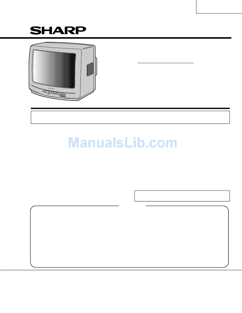
Sharp DV-1600 Series User manual

-
SHARP
SERVICE
MANUAL
:
1
TVSMY82397XV
1
CONTENTS
Page
ELECTRICAL SPECIFICATIONS ..............
1
IMPORTANT SERVICE NOTES ...............
2
ADJUSTMENT
..........................
3
CHASSIS LAYOUT DIAGRAM ...............
12
PRINTED WIRING BOARD ASSEMBLIES. .......
13
BLOCK DIAGRAM .......................
17
+B POWER SCHEMATIC DIAGRAM ............
19
SCHEMATIC DIAGRAMS AND WAVEFORMS .....
21
REPLACEMENT PARTS LIST ..............
26
PAL
SYSTEM
COLOUR TELEVISION
ELECTRICAL SPECIFICATION
Aerial Input Impedance
..........
75 ohm unbalanced
Convergence
..............
Self Converging System
Focus
...................
Quodra Potential Focus
Audio Power Output Rating
.........
.2.0
Watt (max.)
Intermediate Frequencies
Picture IF Carrier Frequency
.........36.875 MHz
Sound IF Carrier Frequency
..........31.375 MHz
Colour Sub-Carrier Frequency
.........32.445 MHz
Power Input
.................240 Volts AC 50Hz
Power Consumption
....................
72 Watt
Speaker Size,
Voice Coil Impedance
......
.8
cm (16 ohms at 400 Hz)
Sweep Deflection
.....................
Magnetic
Tuning Ranges
.............
VHF-Channels 0 thru 12
UHF-Channels 28 thru 63
WARNING
The
chassis
in
this
receiver
is
hot.
Use
an
isolation
transformer
between
the
line
cord
plug
and
power
receptacle,
when
servicing
this
chassis.
To
prevent
electric
shock,
do
not
remove
cover.
No
user
-
personnel. serviceable
parts
inside.
Refer
servicing
to
qualified
service
SHARP
CORPORATING
OF
AUSTRALIA
PTY.
LTD.
64-72 SEVILLE ST.
FAIRFIELD, 2165
N.S.W.
TEL: 02-728-9111

IMPORTANT
SERVICE
NOTES
Maintenance and repair of this
reoeiver
should be done by
qualified service personnel only.
SERVICING OF HIGH VOLTAGE SYSTEM AND
PICTURE TUBE
When servicing the high voltage system, remove static
charge from it by
co~ecting
a
1Ok
ohm Resistor in series
with an insulated wire (such as a test probe) between
picture tube dag and 2nd anode lead. (AC line cord should
be disconnected from AC outlet.)
1. Picture tube in this receiver employs integral implosion
protection.
2. Replace with tube of the same type number for continu-
ed safety.
3. Do not lift picture tube by the neck.
4. Handle the picture tube only when wearing shatter-proof
goggles and after discharging the high voltage
corn-
pletely.
X-RAY
This receiver is designed so that any X-ray radiation is kept
to an absolute minimum. Since certain malfunctions or
servicing may. produce potentially hazardous radiation
with prolonged exposure at dose range, the following pre-
cautions should be observed:
1. When repairing the circuit, be sure not to increase the
high
voltage
to
more
than
27kV,
(at
beam
1000pA)
for
the
set.
2.
To
keep
the
set
in
a
normal
operation,
be
sure
to
make
it
function
on
23.5
kV
+
1SkV
(at
beam
1OOOpA)
in
the
case of the set. The set has been factory
-
adjusted to
the above-mentioned high voltage.
*
. .
If there is a possibility that the high voltage fluctuates
as a result of the repairs, never forget to check for
such high voltage after the work.
3. Do not substitute a picture tube with unauthorized
types and/or brands which may muse excess X-ray
radiation.
BEFORE RETURNING THE RECEIVER
Before returning the receiver to the user, perform the
following safety checks.
1. Inspect all lead dress to make certain that leads are not
pinched or that hardware is not lodged between the
dmsis
and other metal parts in the receiver.
2. Inspect all protective devices such as non-metallic con-
trol knobs, insulating fishpapers, cabinet backs, adjust-
ment and compartment covers or shields, isolation
resistorcapacity networks, mechanical insulators etc.
2

Step
1.
Adjust point
Tuner IFT coil:
ADJUSTMENT
PIF/AFT/SIF
ADJUSTMENT
Connection
(1)
Receive
10
ch.
signal.
(If
reception
of
10
ch.
signal
is
not
satisfied,
receive
VIII band
signal
instead
.)
(2) Connect
sweep
generator to the
tuner’s
test
point.
(Use
a
75
ohm
DC
cut probe.)
To sweep
generator
1
OOOpF
dh
Figure 1.
Sweep
output
level:
80
dB
Note:
The
sweep
generator’s
earth
lead
must
be
grounded near
the test point.
(3)
Connect
reponse
lead
(low
impedance probe with detector)
to
TP201
(collector
of
Q201).
To oscil-
Figure 3.
68f2
(4)
Voltage
setting
of
PIF
AGC:
Apply
DC
3.9V
to
pin
@
of
PIF
IC
(X201).
(5)
Voltage
setting
of
RF
AGC:
Apply
DC
4V
to tuner
AGC.
(6)
Short
TP601
and
TP602
(to
stop
sync
separator circuit).
Procedure
(1)
Adjust the tuner IF
coil
to
have
the
waveform
as
shown
in
Fig.
2
P4.43MHz
36.875MHz
Figure 2.
*Picture
signal
and
carrier
signal
must
have
the
same
level.
3

Step
Adjust point Connection Procedure
2.
36.875
MHz
carrier (1)
Connect
signal
generator
to
pin
(1)
Adjust
T204
so
that
DV
voltage
at
TP203
filter:
@
of
PIF
IC
(IC201).
is
minimum.
T204
Generator’s
output
level:
90
dB
l At the end
of
adjustment,
see
that
there
non modulation (36.875
MHZ)
appears
DC
4V
at
TP203.
(2)
Connect
VTVM
or
oscilloscope
If
not,
readjust from the beginning.
(DC
range)
to
TP203.
(3)
Voltage
setting
of
PIF
AGC:
Apply
DC
voltage
(about
S.OV)
to
pin@
of
PIF
IC
(IC201).
Note:
The
applied
voltage
should not
exceed
DC
7.OV.
3.
AFT rough adjust:
(1)
Connect
sweep
generator
to
(1)
Adjust
T203
so
that
the
depressed
point
T203 pin
@J
of
PIF
IC
(IC201).
of
waveform
is
at 36.875
MHz
as
shown in
Fig.
6.
1
OlOOp
F
Generator’s output level: 90dB
Figure 4.
I
36.875MHz
I
(2)
Connect
response
lead
to
TP203.
I/
36.875MHz
1
To oscil-
loscope
1
OkS2
-=f-+Yl!F~
Figure 6.
Figure 5.
(3)
Short
TP601
and
TP602.
(4)
Voltage
setting
of
PIF
AGC:
Adjust
DC
voltage
(about
S.OV)
to
pin
@
of
PIF
IC
(IC201)
and
adjust
to
have
1
Vp-p
of
waveform
on
oscilloscope.
Note:
The
applied
voltage
should not
exceed
DC
7V.
4

Step
Adjust
.point
Connection Procedure
4. Overall
waveform
(1)
Receive
loch.
signal.
(1)
Check
that
overallwaveform
is
as
shown
If
reception
of
10
ch.
Signal
is
in
Fig.
7.
not
satisfied,
receive
VIII
band
signal
instead.
(2)
Connect
sweep
generator to
tuner’s
test point.
(Use
an
initial
stage
detecting probe.)
Generator’s
output
level:
70
dB
1
(3)
Connect
response
lead
to
TP203.
I
P-36.875MHz
(Use
a
10k
ohm direct
probe
having
been
used
in
AFT
rough
adjustment
.)
(4)
Voltage
setting
of
RF
AGC:
Apply
DC
4V
to
tuner
AGC.
S
RF
AGC:
about
-20
dB
(5)
Short
TP601
and
TP602
(to
stop
sync
separator circuit).
Figure 7.
/
(6)
Connect
120
ohm
damping
resistor between
pins
@
and
@
of
IC201.
/
Note:Damping
resistor
leads
should
’
/
I
be
as
short
as
possible.
;
(7)
F
or
adjustment
of
PIF
AGC:
Connect
DC
voltage
(about
5V)
/
to
pin 13
of
IC201
and
adjust
so
that
waveform
of
TP203
is
at
1
Vp-p.
5.
AFT
fine
adjust:
/
(1)
Receive
standard
PAL
colour bar
T203 signal.
Input intensity:
Over
55
dB
i
(2)
Connect
oscilloscope
to
TP203.
Oscilloscope
range:
O.SV/div.
Sweeing
time
:
20psec/div.
Sync
operation: Horizontal
/
(3)
Connect
signal
generator’s
output
to
TP201.
Generator’s
output
level:
Zero beating
About
50
dB.
Generator’s
output
frequency:
36.875
MHz
f
5
kHz
StiDi
f+
TP201
I
0201
Figure 9.
--1
r
I
t--F
I
1PF
I
I
L
CF2Ol
T2b-;
i
1
’
x
To signal generator
Figure 8.
(4)
Open
tuning control door
(lid),
then
AFT
switch
will
turn
off
automatically.
(5)
Adjust tuning control
to’have
zero
beating on
oscilloscope
as
shown
in
Fig.
9.
5

Step
Adjust point Connection Procedure
(6)
Close
tuning control door (lid),
’
then AFT switch
will
turn
on
automatically.
,
(7)
Adjust
T203
to
have
zero
beating
on
oscilloscope
as
shown
in
Fig.
11.
Adjustment error:
36.875
MHz
+
25
kHz
6.
RF
AGC
cut-in:
1
(1)
Receive
standard colour
bar
signal.
R209
If
reception
of
colour
bar
signal
is
not possible,
receive
VIII band
signal
instead.
Input
intensity:
Within
75
dB
to
85
dB
1
(2)
Connect
oscilloscope
to
TP203.
Oscilloscope
range:
0.2V/div.
Sweeping
time: 20psec/div.
Sync
operation: Horizontal
/
(3)
Turn R209 until there
appears
I
noise
on
oscilloscope
as
shown
I
in
Fig.
10.
/
(4)
T
urn back R209 slowly until
there
disappears
noise
on
oscil-
loscope. At the time, horizontal
sync
signal
should keep on the
I
same
level
as
before.
(Fig.
11)
keep on this level.
1
(5)
Set
signal
intensity at
90
to
95
dB,
and
see
that
there
is
no
black
letter
and
sound beating
on
oscilloscope.
1
(6)
Set
signal
intensity
at
60
to
65
I
dB,
and
see
that there
is
no
Figure 11.
noise
on
oscilloscope.
I
7.
SIF
detection
coil:
I
(1)
Voltage
setting
of
PIF
AGC: (1)
Adjust
T301
so
that
AM
signal
(400
Hz)
T301
Apply
DC
3V
to
pin
@
of
on
oscilloscope
becomes minimum.
IC20
1.
(2)
Adjust sound
volume
to
maximum.
(3)
Connect
signal
generator’s
output
to
pin
$!J
of
IC201.
400Hz
(AM signal)
Figure 13.
!
Figure 12.
Zero
AM signal
l Frequency:
5.5
MHz
l Modulation:
400
Hz,
AM
30%
Figure 14.
l
Generator’s
output
level:
74
dB
6

Step
Adjust point Connection Procedure
(4)
Connect
oscilloscope
to
pin
@J
of
IC201.
Oscilloscope
range:
50
mV/div.
8.
Sub-sound
adjust:
(1)
Receive
PAL colour bar
signal (1)
Adjust
R302
to
have
1.0
Vp-p
of
waveform
R1022
(sound modulation 400
Hz,
100%).
on
oscilloscope
as
shown
in
Fig.
15.
(2) Connect
oscilloscope
to
connec-
tor
Y3
of
sub-sound control
(R302).
(3) Adjust
R302
to
have
1.0
Vp-p
of
waveform (400
Hz)
on
oscilloscope.
(4)
Obtain
a
normal sound
in
the
l.o{’
following
way
:
Figure 15.
Turn
off
the power switch first
and then turn
it
on
again,
and
(2)
Adjust R1022
so
that
output
voltage
of
turn
on
the remote control
speaker
is
1
.O
Vp-p.
transmitter;
then
a
normal
sound
is
obtained.
(5)
Connect
oscilloscope
to
both
ends
of
speaker.
4
(6)
Adjust
R1022
(sub-sound
1
.ovp-p
control
in
sensor
PWB)
so
that
i
output
voltage
of
speaker
is
1.0
vp-p.
Figure 16.

VIDEO CHROMA ADJUSTMENT
Step
Adjust point Connection Procedure
1.
CRT
cut-off
adjust:
eceive
monoscope pattern
R853
;
R-bias
,
(OR
(1)
Turn
screen
control
clockwise
slowly until
signal.
R859;
G-bias
the horizontal
raster
appears
slightly,
and
(Instead
of
monoscope pattern stop it.
R865;
B-bias
signal,
it
is
allowed
to
use
black/
Screen
control
(2)
One
of
the three colours (R,
G
and
B)
white pattern
signal.) appears
first
as
screen
control
is
turned.
(2)
Set
R857
(G-drive)
and
R863 So,
touching
off
the
bias
control
belonging
(B-drive)
at
CENTER
position.
to
the first colour,
use
and
move
the other
Set
R853
(R-bias),
R859
(G-bias)
two
bias
controls
clockwise
until the raster
and
R865.
(B-bias)
at
MIN
becomes white.
position. Note:
Be
careful not
to
cause
the raster
to
(3)
Set
screen
control
at
MIN
appear
too
brightly;
or
there
will
be
a
position. fear
of
CRT
burning.
(4)
Short
TP403
and
TP404. (3)
Turn
screen
control counter-clockwise
(5)
Short
TP401
and
TP402,
then
until
the raster
disappears,
and stop it.
raster
will
appear
on
CRT.
2.
White
balance/
(1)
Receive
monoscope pattern
(1)
Adjust R857 and
R863
to
let the colour
/
background adjust:
signal.
temperature (white)
be
at 6500°K.
R85
7;
G-drive (2)
Set
contrast control at
MAX
I
(2)
Adjust contrast
and
brightness controls
so
R863
;
B-drive
position.
that
beam
current
is
350pA, then
see
that
(3)
Set
brightness control
at
MAX
1colour temperature (background)
is
still
position. at 6500°K.
If
not,
readjust from the
(4)
Connect
beam
arnmeter
to
beginning.
TP603
and
TP604.
(5)
Adjust
R406
(sub-contrast)
so
that
beam
current
is
l.OmA.
3.
/
Sub-contrast adjust:
/
(1)
Receive
monoscope pattern
signal (1)
Adjust
R406
so
that
beam
current
is
/
R406 (Instead
of
monoscope pattern
1
.OmA.
signal,
it
is
allowed
to
use
white
pattern
signal
of
88%
modulation.)
/
(2)
Set
contrast control at
MAX
position.
(3)
Set
brightness
control at
MAX
position.
’
’
(4)
Connect
beam
ammeter to
TP603
and
TP604.
Ammeter setting:
Full
scale
3mA
Connection
of
ammeter:
0
side
to
TP604,
and
@
side
to
TP603.
4.
Chroma
/
(1)
c
onnect pattern generator
I
(PM5508)
to
the
receiver:
the
I
I
antenna input
is
about
71
dB.
/
(2)
Set
contrast
and
brightness
controls at
MAX
position, and
colour control at
CENTER
position.
(1)
Receive
“matrix”
pattern
signal.
(2)
Adjust
T882
so
that
the brightness won’t
vary with
every
1H
change
of
scanning
line.
(3)
Receive
“delay”
pattern
signal.
(4)
Adjust
R805
so
that the
brightness
won’t
vary with every
1H
change
of
scanning
line.
.
(5)
Receive
“phase” pattern
signal,
and
adjust
T801
so
that
the
same
tone
will
be
obtained for
both
upper
and
lower
halves
of
screen.
8

Step
5.
Step
1.
2.
3.
4.
5.
Adjust
point
Pulse
width
adjustment:
R1063
Connection
(1)
Receive
standard
PAL
crosshatch
pattern
signal.
(2) Connect synchroscope to
TPlOOl.
(1)
Adjust
R1063
to
obtain the
pulse
width
of
2
msec.
I-
20ms
1
Figure
17.
Procedure
SYNC/DEFLECTION ADJUSTMENT
Adjust
point
/
Connection
H-freq.
adjust:
R607 (1)
Receive
monoscope pattern
signal.
(2)
Short
TP601
and
TP602.
V-hold
adjust:
R504
’
(1)
Receive
monoscope pattern
I
signal.
H-size
tip (1)
Receive
monoscope pattern
signal.
V-size
adjust
:
1
(1)R
eceive
monoscope pattern
R510
/
I
signal.
V-linearity adjust:
1
R509
/
Vcentering adjust:
c
(1)
Receive
monoscope pattern
SW501
/
signal.
Hcentering
adjust:
1
SW60
1
Procedure
(1)
Adjust
R607
for good horizontal
sync.
Figure 18.
(1)
Adjust R504
so
that
vertical
sync
will
be
proper.
(1)
Arrange
the position
of
H-size
tip
to
have
H-size
be
at
8%
(12%
max.)
of
overscanning.
(1)
Adjust
R5
10
and
R509
at
a
time
for
good
V-linearity.
V
size
should
be
at
8%
(12%
max.)
of
overscanning.
(1)
Adjust
SW501
so
that
V-center
of
picture
is
at
the geometrical center
of
CRT.
(2)
Adjust
SW601
so
that
H-center
of
picture
is
at
the geometrical center
of
CRT.
Geometrical
center
I’
m
-
-
I
-+--
-
--
I
Figure 19.
9

CRT ADJUSTMENT
Step
Adjust point Connection Procedure
1.
Focus control
(1)
Receive
monoscope pattern
t
signal.
1
(1)
Adjust focus control
to
have
best focus
at the central
area
of
CRT.
,
(2)
Set
contrast control at
MAX
’
position.
I
(3)
Set
brightness
control
at
MAX
/
position (with
1
.OmA
of
beam
1
current).
/
(Instead
of
monoscope pattern
I
I
2.
Purity magnet
signal,
it
is
allowed
to
use
white
/
pattern
signal
of
88%
modulation.)
i
I
I
(1)
Receive
monoscope pattern
signal,
Figure 20.
(2)
Degauss
CRT
shadow
mask
with
1
degaussing
coil.
,
(3)
Prior
to the adjustment, operate
/
I
the
receiver
for
more
than
10
1
(4)
~~~~ty
magnets
at
the
horizontal position.
(5)
Bring
deflection yoke
as
near
purity
magnet
as
possible.
j
(6)
Set
R853
(R-bias)
and
R865.
/
(B-bias)
at
MIN
position, then
turn
R859
(G-bias)
until
green
raster
appears.
Green
Figure 21.
(7)
Adjust
purity
magnets for
a
uniform
green
vertical
band
at
I
/
the center
of
CRT
screen.
For
this
adjustment, motion
of
each
magnet should
be
as
slight
I
as
possible.
1
(8)
Shift deflection yoke toward
I
CRT
to
achieve
uniform
green
,
I
I
purity
on
the
entire
of
CRT
I
screen.
I
(9)
Perform white
balance
opera-
/
/
tion,
and
see
if
white
balance
in
I
picture
is
normal.
I
3.
’
Convergence
/
(1)
Receive
crosshatch pattern Static (center)
convergence:
I
signal.
/
(2)
Set
contrast control at
(1)
Rotate
4-pole
magnet to
converge
red
and
blue
lines.
I
CENTER
position.
j
(3)
Set
brightness
control
at
1
(2)
After completing
red
and
blue
center
j
convergence,
rotate
6-pole
magnet
to
CENTER
position.
;ly
converge
the
red
and
blue
and
green
lines.
namic
convergence:
.
:
(3)
Convergence
of
the three colour
fields
at
,
I
the
edges
of
CRT
screen
is
accomplished
I
by positioning
of
deflection yoke tilt
I
adjustment
wedges.
j
(4)
After the adjustment,
secure
deflection
yoke with
wedges.
10

REF. NO.
PART NO.
DESCRIPTION
CODE REF. NO. PART NO. DESCRIPTION CODI
PRINTED WIRING BOARD ASSEMBLY
&RYlOUt
RRLYUOOI2CEZZ
&Relay
”
<j
j
‘7
v.v
j
‘+a
“=p
A
F701
~QFSC2022TAZZ
Fuse
Link,
?-2A
Y
^,
PWB-A
DUNTK2260DE24
Mother Unit
-
PWB-B
DUNTK2261
DE22 CRT Socket Unit
-
PWB-C
DUNTK2156DE02
Remote Control Receive Unit
-
PWB-D
DUNTKZI
57DE03
Tuning Unit
-
PWB-E
DUNTK2158DEOl
LED Display Unit CABINET PARTS
-
PWB-F
DUNTK2159DEOl
Switch Unit
I
-
1
i
CCABAI
288CE02
Front Cabinet Ass’y
PWB-G
DUNTK2160DEOl
Control Unit
-
l-lNot Available Front Cabinet
PWB-H
DUNTK2161
DE02 Mains Switch Unit
-
-
l-2JBTN-1063CESA Eject Button
l-3
G&RF1
174CESA
Front Door
l-4
GCiJVA3015CESA
Flap Cover
MISCELLANEOUS l-5
HiNDMl982CESA
Model Name Plate
l-6
HiNDP1405CESA
Indicator Sheet
!@R7011
RMPTPUO28CEZZ
1
Positive Coefficient Themister
AG
l-7
HiNDMl983CESA
Indicator Plate (Inside the
X801 RCRSBOOI GCEZZ Crystal
4.43MHz
OSC AM Front Door)
FB601,
RBLN-OOIOCEZZ Ferrite Bead AC l-8
HBDGB3053CESA
SHARP Badge
701, l-9
HBDGS3002CESA
Colour Badge
602 I-IO
HiNDPl386CESA
Channel Indicator Cover
QTANJ0301
CEZZ Video & Audio Terminal AX
I-II
H DECO01 64CESB Power indicator Cover
RRMCGOI 25CESA Remote Control Transmitter BE l-l 2
HDECA0289CESA
Decoration Metal
RRMCU0079CEZZ
Remote Control Receiver AW I-13
LANGK0086CESA
Front Grass Bracket
_
“<
t
b:
VTUVTE-I
AH/I/
Tuner
BL
2
CCABBI
337CEOl
Back Cabinet Ass’y
VSP0080PB66WA
Speaker AT
2-1
Not Available Back Cabinet
5:
-
QACCL3005CEZZ
AC-Cord AN 3
GDZRTI
021 CESA Door
OS?%%081
5CEZZ CRT Socket
AL 4 JBTN-1
OGOCESB
Main Switch Button
-v
PMAGF3006CEZZ
Purity Magnet AK 5 JKNBKI 138CESC Knob (Contrast/Colour
SW501
QSW-B0015CEZZ
V-Center Adjust Switch AC /Brightness Picture Tone)
SW601
QSW-B0015CEZZ
H-Center Adjust Switch AC 6 JKNBKI
153CESA
Knob (System Selector)
&W701
:
QSW-WI 37CEZZ
Mains Switch AL 7 HPN
LCI
407CESA
Panel
SW1 001 QSW-B0006CEZZ Relay ON Switch AC 8
PG
LSC0008CESA
Front Grass
&W%IO2
QSW-KfJO09GEZZ
Channel Up Switch
AD 9
LX-BZ3118CEZZ
Screw
~x~tC103
QSW-K0009GEZZ Sound Down Switch
AD
!&W?OO4
QSW-K0009GEZZ Sound Up Switch
AD
IS!&?005
QSW-KOOO9GEZZ
Power Switch AD
IsMf”xUCl6
QSW-POO36GEZZ
AFT Switch AF
&Wtoo-I QSW90023CEZZ
System Switch
AE
*”
?
29

REMOTE
CONTROL TRANSMITTER
PARTS
iRRMCGOl25CESAl
Ref. No. Part No. Description
&de
Ref. No.
Part No. Description
IC3001
RH-iX0187PAZZ
IC
AV
03001
95G8E453T
LED
Q3001
VS2SCl815YWl
E Transistor [2SC1815(Y)l
A8
CF3001
95G5E-371
T
Ceramic Oscillator
Q3002
95G5T-135A
Transistor
AD
-
REMOTE CONTROL TRANSMITTER HOUSING PARTS LIST
Code
AK
AG
,
Ref. No. Part No.
Description
Code Ref. No.
Part No.
Description
code
1
GCoVA3015CESA
Flap Cover
AK 12 XTASDSOPl2000
Screw
AA
2NSFTTOOO9CEZZ Shaft
AB 13
MSPRC0021 CEZZ
Spring (Eject Shaft)
AA
3
MSPRD0005CEFJ
Spring (Flap Cover)
AA 14
LHLDZll
SOCEZZ Holder AB
4
PSPAHOOl9CEOO
Spacer
AA 15
NFSTZOOll CEFW Eject Shaft
AB
5
LANGT9270CEFW Bracket AD 16
JBTN-1063CESA Eject Button
AE
6PCLiCl
001 CEZZ
Clip
AA 17
PM
LT-OO64CEOO
Cushion
AA
7
GCbVH9145CEOO
Rack Guide
AB 18 LHLDWlO46CEZZ Wire Holder AA
8
LX-CZ3001 CEFD Screw (Damper)
AA 19 XTASD30P12000
Screw
AA
9
PDMPFl002TAZZ
Damper
AD 20
PCoVW3007CEZZ
Barrier
AC
10
MSPRC0030CEZZ
Spring (Rack) AA 21
PSPAZOO23CEZZ
Spacer
AA
11
NSFTZ0005CEZZ
Rack AC
T3979-S
Printed in Japan
M.W

Step
Adjust point Connection Procedure
A
B
‘-4-I
(Adjustment in
A direction) (Adjustment in
B direction)
Figure 22.
DEFLECTION YOKE
CLAMP SCREW
\rTAPE
I
CR
-PURITY MAGNETS
,
L
DEFLECTION YOKE TILT
ADJUSTMENT WEDGE
11

1
I
2
a
5
>
m
Aa!
I
(n
F:
:
se
@I
0’
II
9’
@D
C._i-l‘g
0.3
-
P
a
;
~.“~~~
;-
5
O
;
fe
;y<
~
j-f
$g”
8
8
:cI
?I
8
ii
l
3’
Ho$
R
n
B
;
8
5
.9.
O’
k---+
0’6
8
51;
gr
g’
go;
$1
D
El
1
‘$+A
I
s
z
LH
l :
;1
l z
57
+===
D
g
--I
;
I-
\
a
p
J
h
5
t
i?
k
0
2
-I
ii
u
,w
,I;-
/
I
3
;m
2
c-:
N
::h
;
’
5
:
:.-,*
i'
;
I
:--,W
'
I
I
I
:-sx,e
)
j
':;.
LJ
I-x
\
-,a
I
3
I
4
I
5
I
6
12

PRINTED WIRING BOARD ASSEMBLIES
“I
BL
tsi
.*
5
u
aa
Ea
.‘C
Figure
13.
PWB-A
(Wiring
Side)
Figure
14.
PWB-B
(Wiring
Side)
1I
2
I
3
I
4
I
5
I
6
I
7
13

I
I
8
I
9
I
10
I
11
1
Figure
16.
PWB-C
(Wiring
Side)
r-l
swi006
.FT-SW
-1
1
z!J
e5
PUBFZL57‘E
Figure
16.
PWB-D
(Wiring
Side)
Figure
17.
PWB-E
(Wiring
Side)
5
I
7
I
8
I
9
I
10
I
11
I
12
14

Figure 18. PWB-F (Wiring Side)
PWCFZl60r.E
s
-w
?e”
--2
c
Figure 19. PWB-G (Wiring Side)
Figure 20. PWB-H (Wiring Side)

E
-3
I
4
I
5
I
I
l3kK
DlAGRAl
PWB-D
Tunmg
VR
-----mm
AFT SW1008
PWB-E
CH-IND-LED
D1023
-
D1032
*
VTAMP.LED STAND-BY
-
a1002BLANKER IND-SW
IC
12V
REGU
a1 001 01005
01007.
Dli
I
1
Y1
CH-CONTROL
,C
IClOOl
w
A
-
7
-
SUB-SInvertor
Amp
R1022
-
Q1008
rPWB-F
CONTROL-SW
e
I
t
11
SW1002.
SWl~
-
RC
I
sw1003,
SW1005 RIG DECORDER EXT
Vhdeo
EXT SOUND
81
CONTROLER
-
AMP &SW AMP &DC-ATT
IC1002
Q1012.01011
IC1003
b
RRMCU0079CEZ.Z
P/C PRE-AMP
IC3002
ho-
RIG AMP.
01003
-
C
t
Y
PICTURE S-OUT AMP
IC501 H-DRIVE
, ,
t
Lz”ol
H-DRIVE H-OUT
-+TRANS
*&
DAMPPER
-
T601
0602
H-FREQ.
H-CENT
R607
SW
t
SW601
v,
+12vDC
1
1I
H.V
’
1
.
DETEC- PROTEC- 12v
TOR TOR REGULATOR
*
:
0608 a604 a603
t
0
12v
’
RECT
e--
D605
0
-
+15ov
SL.
REC
-
D603
C
ST.
a7c
1I
2
I
3
I
4
I
5
I
6
I
I
17

K DIAGRAM
3Y
12V
REGULATOR DC-SUPPLY
-
Q1007,
D1012
-
RECT
DC-SUPPLY
D1009,
DlOOl
-
TRANSFORMER
-1
4,
TlOOl
JND
i
C-ATT
)
STAND-BY-SW
PRIVER
Q1006
STAND-BY
c
RERAY
RYlOOl
&
r
DC AMP.
5
DRIVE
PULSE AMP
-
‘lo’7
V-SIZE SW
01015 Q1018
a1021
-
a1019
t
I
t
50Hz/60Hz
Dmnmmator
01013.
a1014
H-CENT SW V-HOLD SW
a1120
-
V-CENT. SW
-
a1 022
EXT
Audio
IN
VIDEO
FILLTER
f
>EXT
Video IN
CONTRAST
R1053
I
1
COLOUR
CONT.
01054
BRIGHT-
CONT. R1055
RICTURE
R1056
-
R-AMP
-
0851
-I
R-BIAS
R853
-’
. CRT
G-AMP
_I
w-
420FSTC03
-
Q852
K
t
I .
18
Table of contents
Other Sharp TV manuals

Sharp
Sharp LC-32SH130E Manual

Sharp
Sharp 21BM2GMK2 User manual

Sharp
Sharp 21LF-90H User manual

Sharp
Sharp LC-42RD2EA User manual

Sharp
Sharp 36R-S60 User manual

Sharp
Sharp 54DS05SN User manual

Sharp
Sharp LC-32DH57E-GY User manual

Sharp
Sharp LC60E77UN - 60" LCD TV User manual

Sharp
Sharp Aquos LC-20S4E User manual

Sharp
Sharp 28JS-74SS User manual

Sharp
Sharp 29H-FX3M User manual

Sharp
Sharp 28LF-96EC User manual

Sharp
Sharp 21G-FX10L User manual

Sharp
Sharp 21H-FV5RU User manual

Sharp
Sharp 21LF-90C User manual

Sharp
Sharp LC-40FI2242KF User manual

Sharp
Sharp LC-40LE530E User manual

Sharp
Sharp 32SF56B User manual

Sharp
Sharp 63CS-03S User manual

Sharp
Sharp LC-24DHG6131KF Technical manual